Amico Alert-4 Operating & Maintenance Manual
Lcd ethernet area alarm
Hide thumbs
Also See for Alert-4:
- Operating & maintenance manual (25 pages) ,
- Operation & maintenance manual (32 pages)
Table of Contents
Advertisement
Quick Links
Advertisement
Table of Contents

Related Manuals for Amico Alert-4


Summary of Contents for Amico Alert-4
- Page 1 Operating & Maintenance Manual Alert-4 LCD Ethernet Area Alarm...
-
Page 2: Table Of Contents
Contents User Responsibility Introduction Features Description of the Alarm Shipment Details The Alarm Back Box The Frame/Module Assembly Description of Modules System Power Supply LCD Module Sensor Module Installation Guide 7-11 The Alarm Box For Local Sensors Only Standing Pressure Test Sensor Local Remote... - Page 3 Contents Recorded History Log Web Audio Programming Gas Locations Amico Mobile Eco System App 21-22 Model Numbers Spare Part Numbers 24-25 Sensors Accessories/Misc. Demand Check Valves Dimensions LCD Alarm Alert-4 Sensor Troubleshooting 27-28 Appendix A Wiring Diagram: LCD Board Appendix B...
-
Page 4: User Responsibility
Should such repair or replacement become necessary, please contact Amico Corporation or their distributors. All alarms should not be repaired or altered without prior written or verbal approval from Amico Corporation or its distributors. Failure to comply will void all warranty on the alarm. -
Page 5: Introduction
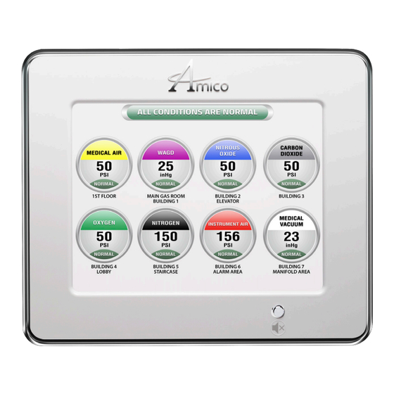
Introduction The Amico Area LCD Alarm System (Alert-4) incorporates the latest microprocessor based technology for alarm and surveillance systems. The alarm has been designed to provide user flexibility and reliability. This manual shall enable the customer to install, use and maintain the alarm appropriately. -
Page 6: Description Of The Alarm
Description of the Alarm SHIPMENT DETAILS When you receive an Alert-4 LCD series alarm from Amico Corporation, the package will consist of three main sections: the Alarm Back Box, Sensors and the Frame/Module Assembly. THE ALARM BACK BOX The Alarm Back Box contains the auto-switchable System Power Supply with an ON/OFF switch, a built-in fuse and terminal blocks (115 to 220 VAC - 50 to 60 Hz). -
Page 7: Sensor Module
With a wrench, tighten the nut so that it makes a good seal. Note: Maximum input pressure not to exceed more than 249 psi for pressure sensors and 30 inHg for vacuum sensors. www.amico.com... -
Page 8: Remote
Attach the frame wire with 2 dome head screws (provided with frame in a plastic bag). This will allow the frame assembly and back box to the fastened securely together. iii. Close the LCD screen with a back box by tightening two screws provided with divider plate. Amico Corporation... -
Page 9: System Power Supply
Cover the frame and tighten the side screws. CAUTION: The microprocessor circuitry on the Alert-4 alarm contains sophisticated integrated semiconductors. DO NOT TOUCH any of the components on the board. Static discharge can cause the modules to malfunction or become damaged. -
Page 10: Sensor Module
When remote sensors are used, ONLY a #22 gauge stranded, shielded twisted pair cable must be used (BELDEN #8451 or equivalent, supplied by others). • Do not ground the shield drain wire at sensor or inside the alarm panel back box 10 Amico Corporation... -
Page 11: Lcd Display Module
Carefully place the front frame over the frame panel. Screw in the screws that were removed in Step 5, part ii. The alarm shall now be ready for use. CAUTION: To protect from static electricity, ensure to discharge body static before installing the Medical Gas alarm and sensors. www.amico.com... -
Page 12: Configuration Guide
NOTE: It is best to use a switch instead of a hub because the device communicates at 10 Mbps. A switch is better able to support this speed, improves network performance and keeps unnecessary traffic from being routed to the alarm. • Amico Alert-4 Area alarm will be set to factory default setting, the IP Address, Subnet Mask and Gateway as following: IP address: 192.168.1.100... -
Page 13: Changing Ip Address
Configuration Guide CHANGING IP ADDRESS Open the SD Card with the files provided by Amico Corporation. Open the file named “network” to change the network IP address. Change the default IP address to the desired IP address, Gateway and Subnet Mask; then save the file by clicking “File“... - Page 14 IP ADDRESS: 192.168.1.100 If the configured information does not appear on the screen, repeat the steps above. If the problem persists, contact Amico Corporation for further assistance. • Once the information is visible on the LCD Alarm screen, leave the SD Card in the slot for approximately 1 minute in order for the information to be completely uploaded onto the alarm, and then proceed to remove the card.
-
Page 15: Email Setup
The following parameters are needed to activate the email service. Information systems personnel will be able to provide the necessary parameters. Open the network configuration file on the SD card provided by Amico to input the SMTP server parameters. IP_SMTP= (provide SMTP server IP address) -
Page 16: Text Setup
The following parameters are needed to activate the text service. Information systems personnel will be able to provide the necessary parameters. Open the network configuration file on the SD card provided by Amico to input the SMTP server parameters. IP_SMTP= (provide SMTP server IP address) -
Page 17: Connecting To Alarm
Start the web browser (Google Chrome, Internet Explorer) • Enter the device IP address eg: (http://192.168.1.1xx) in the browser’s address bar*. NOTE: To find Alarm IP Address, press reset button on the back of the Alert-4 Area Alarm. DIRECT CONNECTION SIMPLE UNMANAGED NETWORK Switch www.amico.com... -
Page 18: Complex Managed Network
To view the logs Remove the SD card from the SD card slot. Plug the SD card to a PC card reader and open the SD card. Open the file called “ERROR” by double clicking File will displays history logs. 18 Amico Corporation... -
Page 19: Web Audio
If the PC audio doesn't turn on automatically, click mute and re-activate the alert to turn PC Audio ON. Note: By muting the audio in the web page doesn't not silence audio at the alarm panel. To silence press mute button at the panel. www.amico.com... -
Page 20: Programming Gas Locations
When file is uploaded, the panel will display the location under the gas icons. • If the gas location text does not appear on the screen, repeat step #6. If the problem persists, contact Amico Corporation for further assistance. -
Page 21: Amico Mobile Eco System App
NOTE: If Alert-4 alarm is given with local IP address, the phone must be connected to local WiFi before connecting the app to the Alert-4 alarm. If Alert-4 alarm is given with global IP address, connecting the phone to local WiFi is not needed. - Page 22 Amico Mobile Eco System App Click to Open Manuals Click to Contact Amico Slide Left to Delete Device Display Exact Image of the Alarm Re-order mode Click to add more devices Press and hold the device screen Device Manual to move the device...
-
Page 23: Model Numbers
”GAS” Defines the Type of Gas: Oxygen The “L” Defines the Language: Medical Air English (NFPA) MedVac English (CSA/ISO) = Nitrous Oxide French (CSA/ISO) = Nitrogen Spanish (NFPA) Carbon Dioxide WAGD (NFPA) AGSS (CSA/ISO) Instrument Air NOTE: Each Alert-3 Sensor comes with an A2P-PIPE www.amico.com... -
Page 24: Spare Part Numbers
A2P-BOXASS-3LCD Alarm Back Box Assembly 3-Station Alert-2 A2X-BOX-ASY-3LCD Alert-3 LCD Alarm Box without Power Supply A4A-AREA-FRAME LCD Alarm Frame Assembly for Alert-4 Area A2P-PIPE-AIR Pipe, Demand Check, Gas Specific Label AIR A2P-PIPE-OXY Pipe, Demand Check, Gas Specific Label OCY A2P-PIPE-VAC... -
Page 25: Demand Check Valves
DISS Demand Check, Nut and Nipple - NIT S-DIS-KIT-WAG DISS Demand Check, Nut and Nipple- WAG S-DIS-KIT-AGS DISS Demand Check, Nut and Nipple- AGS S-DIS-KIT-IAR DISS Demand Check, Nut and Nipple - IAR S-DIS-KIT-CO2 DISS Demand Check, Nut and Nipple - CO2 www.amico.com... -
Page 26: Dimensions
[64] [64] [19] 10 3/4 [272] NOTE: LCD Alarm itself is 8 lbs. Each sensor is 1 lb. ALERT-4 SENSOR 6" - 8" [0.1m - 0.2 m] #22 gauge 1 7/8 1/2"-14 NPSM [13] stranded, shielded and twisted pair [48]... -
Page 27: Troubleshooting
LCD module by using wiring diagram in Appendix D or Appendix E Requires calibration Re-calibrate pressure reading (see page 11, Step 9 - iv, “CURRENT OFF SET”) Defective sensor Replace the sensor module Defective LCD display Replace the LCD module www.amico.com... - Page 28 **Must leave an SD card to the SD card slot to record alarm logs** **Set the DATE & TIME appropriately** FACTORY DEFAULT SETTING GAS Mid Pressure 60 psi 40 psi Vacuum 32 inHg 12 inHg High Pressure 195 psi 140 psi 28 Amico Corporation...
-
Page 29: Appendix A Wiring Diagram: Lcd Board
Keep the shield drain wires as short as possible and taped to prevent from grounding, so they cannot touch the front panel circuit board when front panel is closed. To protect from static electricity, ensure to discharge body static before installing the Medical Gas Alarm and Sensors. www.amico.com... - Page 30 LCD Module Blue (5 VDC) Orange (15 VDC) CAUTION: Verify that power has been switched off prior to working on the alarm Risk of electric shock, disconnect power at the circuit breaker before removing power supply shield 30 Amico Corporation...
- Page 31 Appendix C WIRING DIAGRAM: LCD DISPLAY MODULE - ALARM BUZZER Optional: To Amico Manifold Universal Remote Buzzer NC COM NO 12V GND Optional: Abnormal Alarm To Amico: Master Module or Building Management System NO COM NC 12V GND NO COM NC 12V GND...
- Page 32 Do not ground the shield drain wire at sensor or inside alarm panel back box Reset +12V Button GRND CAUTION: To protect from static electricity, ensure to discharge body static before installing the Medical Gas Alarm and sensors 32 Amico Corporation...
- Page 33 For multiple sensors, a Orange (15 VDC) multi-conductor twisted pair cable can be used. Blue (5 VDC) Reset +12V Button GRND NOTE: For multiple sensors, a multi-conductor #22 Gauge stranded, shielded and twisted pair cable ONLY must be used. www.amico.com...
- Page 34 Maximum 10,000 ft [3,000 m] Cable: Minimum #22 gauge stranded wire Signal: 5 VDC < 5 µA LCD Generic Alarm: Output: Dry Contacts NC, open on Alarm Rating: 30 VDC 1.0 Amps. 60 VDC 0.3 Amps. 125 VAC 0.5 Amps. 34 Amico Corporation...
- Page 35 The following rules along with references to this manual’s schematics clarify wiring requirements. Two conductor cables (must be #22 gauge stranded, shielded and twisted pair cable type) are required for each Gas Sensor module to the Gas Input board. www.amico.com...
- Page 36 Amico Corporation | 85 Fulton Way, Richmond Hill, ON L4B 2N4, Canada 71 East Industry Court, Deer Park, NY 11729, USA Toll Free Tel: 1.877.462.6426 | Tel: 905.764.0800 | Fax: 905.764.0862 Email: info@amico.com | www.amico.com ACP-OPER-MAINT-ALERT4-LCD-AREA-ALRM 09.24.2019...
Need help?
Do you have a question about the Alert-4 and is the answer not in the manual?
Questions and answers