Amico Alert-3 LCD v2.3 Operating & Maintenance Manual
Hide thumbs
Also See for Alert-3 LCD v2.3:
- Operating & maintenance manual (32 pages) ,
- Installation operating & maintenance manual (28 pages) ,
- Retro-fit manual (4 pages)
Table of Contents
Advertisement
Quick Links
Advertisement
Table of Contents
Troubleshooting

Related Manuals for Amico Alert-3 LCD v2.3


Summary of Contents for Amico Alert-3 LCD v2.3
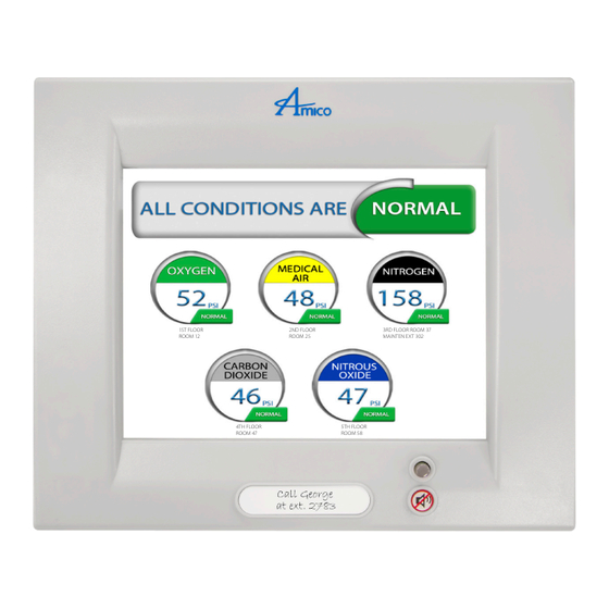
- Page 1 Operating & Maintenance Manual Alert-3 LCD Alarm v2.3 1ST FLOOR 2ND FLOOR 3RD FLOOR ROOM 37 ROOM 12 ROOM 25 MAINTEN EXT 302 4TH FLOOR 5TH FLOOR ROOM 47 ROOM 58 Andersen Medical Gas 12 Place Lafi fi tte Madisonville, LA 70447 http://www.TheMedicalGas.com 1-866-288-3783...
-
Page 2: Table Of Contents
Contents User Responsibility Introduction 4 - 5 Features Description of the Alarm Shipment Details The Alarm Back Box The Frame Assembly System Power Supply LCD Module Sensor Module Installation Guide 7 - 11 The Alarm Back Box For Local Sensor Only Standing Pressure Test Sensor 7 - 8... - Page 3 Contents Dimensions Troubleshooting 17 - 18 Appendix A Wiring Diagram: LCD Module Appendix B Wiring Diagram: Auto-Switch Power Supply Appendix C Wiring Diagram: LCD Display Board - Alarm Buzzer Appendix D Wiring Diagram: LCD Display Board - Local Sensor Appendix E Wiring Diagram: LCD Display Board - Remote Sensor Appendix F Wiring Diagram: LCD Display Board - Master Module...
-
Page 4: User Responsibility
All alarms should not be repaired, or altered without prior written or verbal repair or replacement become necessary, please contact Amico Corporation Alarms should not be altered without prior written or verbal approval from Amico Corporation or a factory trained approval of Amico Corporation or it’s distributors. Failure to comply will void All alarms should not be repaired, or altered without prior written or verbal or their distributors. -
Page 5: Features
• LCD Alarm available in 1 to 8 gases Description of the Alarm SHIPMENT DETAILS When you receive an Alert-3 LCD alarm from Amico Corporation, the package will consist of three main sections: the Alarm Back Box, Sensors and the Frame Assembly. THE ALARM BACK BOX The Alarm Back Box contains an auto-switchable power supply with an ON/OFF switch, a built-in fuse and terminal blocks (115 to 220 VAC - 50 to 60 Hz). -
Page 6: System Power Supply
This module also contains a fail-safe relay that de-energizes when the buzzer is activated. This relay can be used with the Amico Remote Buzzer for applications requiring a remote audible alarm, master alarm or a Building Management System. -
Page 7: Installation Guide
(0 to 30 inHg) - Vacuum, WAGD, AGSS CAUTION: To protect from static electricity, ensure to discharge body static before installing the Medical Gas Alarm and sensors Do not ground the shield drain wire at sensor or inside alarm panel back box www.amico.com... -
Page 8: Remote
Remove the frame assembly from its protective box. All alarms should not be repaired, or altered without prior written or verbal approval of Amico Corporation or it’s distributors. Failure to comply will void ii. Remove the corner screws from the front frame section (4 screws). -
Page 9: System Power Supply
All alarms should not be repaired, or altered without prior written or verbal approval of Amico Corporation or it’s distributors. Failure to comply will void all warranty on the alarm. Installation Guide WARNING CAUTION Statements in this manual preceded by the words... -
Page 10: Local
COM (Common), NO (Normally Open) or NC (Normally Closed), using the diagram in Appendix A. See Appendix G for contact rating. Once the sensors are connected and the power has been switched on, use the following steps to setup the LCD Alarm. Amico Corporation... -
Page 11: Lcd Display Setup
Carefully place the front frame over the frame panel. Screw in the screws that were removed in Step 5, part ii. The alarm shall now be ready for use. CAUTION: To protect from static electricity, ensure to discharge body static before installing the Medical Gas Alarm and sensors. www.amico.com... -
Page 12: Programming Gas Locations
SD Card (location.txt) appears on the LCD Alarm Screen. • If the gas location text does not appear on the screen, repeat step #6. If the problem persists, contact Amico Corporation for further assistance. 7. Once the text is visible on the LCD Alarm, leave the SD Card in the slot for approximately 1 minute in order for the information to be completely uploaded onto the alarm, and then proceed to remove the card. -
Page 13: Model Numbers
N2O = Nitrous Oxide F = French (CSA/ISO) = Nitrogen S = Spanish (NFPA/ISO) CO2 = Carbon Dioxide WAG = Waste Anesthetic Gas Disposal AGS = Anesthetic Gas Scaveng- ing System NOTE: Each Alert-3 Sensor comes with an A2P-PIPE = Instrument Air www.amico.com... -
Page 14: Spare Part Numbers
A2P-PIPE-EVA Pipe, Demand Check,Gas Specific Label WAG A2P-PIPE-IAR Pipe, Demand Check,Gas Specific Label IAR A2P-PIPE Pressure Module Pipe Assembly (Alert-2) A3P-DEMO-CASE Alert-3 Demo Alarm A3X-P-SW-PVCAP LCD PVA Switch Cap-Gray A3X-LCD-LABEL LCD Alarm Front Label A3X-LCD-LABEL-MUTE Alert-3 Mute Label Amico Corporation... -
Page 15: Demand Check Valves
Conv For 1 Gas Puritan Benet Series A2P-CONKIT-SQUCOG-1 Conv For 1 Gas Squire Cogswell/ Product A2P-CONKIT-TRITEC-1 Conv 1 Gas Tri-Tech/Beconmedes/PB Mega A3P-LCD-FILLER-4 Alert-3 Filler Frame 4 - Station A3P-LCD-FILLER-5 Alert-3 Filler Frame 5 - Station A3P-LCD-FILLER-7 Alert-3 Box Filler Frame 7 - Station www.amico.com... -
Page 16: Dimensions
[19.05] or cable ALERT-3 SENSOR 6" - 8" [0.1m - 0.2 m] #22 gauge 1/2”-14 NPSM [13] stranded, shielded and twisted 1.88 [48] pair cable supplied Wrench Flats [25] (Approximate, can vary) DISS Connector 1/2" Conduit Connection Amico Corporation... -
Page 17: Troubleshooting
Connection of the DC power cable from Disconnect the DC power cable from system power supply to LCD alarm is the LCD module and then reconnect. If loose audible alarm still persists, replace the System Power Supply unit. Faulty push button Replace the LCD alarm. www.amico.com... -
Page 18: Troubleshooting
(see pg. 11, Step 9) Faulty sensors Replace sensors FACTORY DEFAULT SETTING GAS Mid Pressure = 60 psi = 40 psi Vacuum = 32 inHg = 12 inHg High Pressure = 195 psi = 140 psi Amico Corporation... -
Page 19: Appendix A
Amico Corporation or their distributors. All alarms should not be repaired, or altered without prior written or verbal approval of Amico Corporation or it’s distributors. Failure to comply will void all warranty on the alarm. SD Memory Card Slot... -
Page 20: Appendix B
DC Power Cable: All alarms should not be repaired, or altered without prior written or verbal Connect to Annunciator Module approval of Amico Corporation or it’s distributors. Failure to comply will void all warranty on the alarm. WARNING CAUTION Statements in this manual preceded by the words... -
Page 21: Appendix C
Appendix C WIRING DIAGRAM: LCD DISPLAY BOARD - ALARM BUZZER Optional: To Amico Manifold Universal Remote Buzzer NC COM NO 12V GND Generic Alarm Dry- Contact Fault Indicator (to Building Management System/Master) NO COM NC 12V GND NO COM NC 12V GND NOTE: www.amico.com... -
Page 22: Appendix D
6”-8” [0.1m-0.2m] supplied Black NOTE: Do not ground the shield drain wire at sensor or inside alarm panel back box CAUTION: To protect from static electricity, ensure to discharge body static before installing the Medical Gas Alarm and sensors Amico Corporation... -
Page 23: Appendix E
MUST be placed in a metallic conduit Note: For multiple sensors, a multi-conductor twisted pair cable can be used. Note: For multiple sensors, a multi- conductor #22 gauge stranded, shielded and twisted pair cable ONLY must be used www.amico.com... -
Page 24: Appendix F
(supplied by others) Remote location Alarm Master Module #22 Gauge twisted pair shielded cable Black 5,000' [1,500m] max. Dry Contact to Amico: Master Module or Building Management System Source Equipment Source Note: Jumper any unused points Equipment on the Master module. NOTE:... -
Page 25: Appendix G
Maximum 10,000 ft [3,000 m] Cable: Minimum #22 gauge stranded wire Signal: 5 VDC < 5 µA LCD Generic Alarm: Output: Dry Contacts NC, open on Alarm Rating: 30 VDC 1.0 Amps. 60 VDC 0.3 Amps. 125 VAC 0.5 Amps. www.amico.com... -
Page 26: Appendix H
The following rules along with references to this manual’s schematics clarify wiring requirements. Two conductor cables (must be #22 gauge stranded, shielded and twisted pair cable type) are required for each Gas Sensor module to the Gas Input board. Amico Corporation... - Page 27 www.amico.com...
- Page 28 12 Place Lafi fi tte Madisonville, LA 70447 http://www.TheMedicalGas.com 1-866-288-3783 Amico Corporation | 85 Fulton Way, Richmond Hill, ON L4B 2N4, Canada 71 East Industry Court, Deer Park, NY 11729, USA Text Toll Free Tel: 1.877.462.6426 | Tel: 905.764.0800 | Fax: 905.764.0862 Email: info@amico.com | www.amico.com...
Need help?
Do you have a question about the Alert-3 LCD v2.3 and is the answer not in the manual?
Questions and answers