
Related Manuals for Amico Alert-2


Summary of Contents for Amico Alert-2
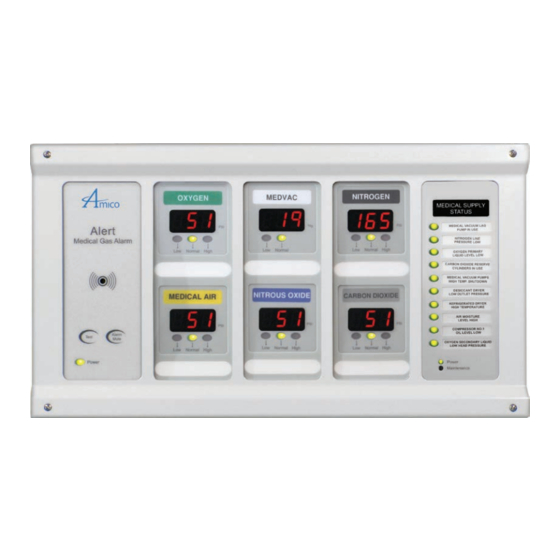
- Page 1 Operating & Maintenance Manual Alert-2 Microprocessor Based Digital Alarm System v6.3...
-
Page 2: Table Of Contents
Introduction Features Description of the Alarm Shipment Details The Alarm Back Box The Frame/Module Assembly Description of the Modules Common to all Alert-2 Alarms System Power Supply Annunciator Module Blank Module Compact Display Module Sensor Module Master Alarm Master/Nema 4 Status Module... - Page 3 Contents Annunciator Module Noise Level Control Control of Remote Alarm Buzzer Steps to Re-Calibrate the Sensor from Compact Module Compact Display Module - To Change High and Low Pressure Set Points 10-14 PSI/kPa/BAR Selections Inch Hg/kPa/BAR Selections Common Settings for Pressure and Vacuum Setting Factory Default Setting Gas Identification Switches Chart of Gas Specific Settings of Dip-Switches...
- Page 4 Contents Appendix A Wiring Diagram: Auto-Switching Power Supply Appendix B Wiring Diagram: Annunciator Appendix C Wiring Diagram: Automatic Voice/Pager Dialing System Appendix D Wiring Diagram: Compact Display Module - Local Sensor Appendix E Wiring Diagram: Compact Display Module - Remote Sensor Appendix F Wiring Diagram: Compact Module to Master Appendix G...
-
Page 5: User Responsibility
Should such repair or replacement become necessary, please contact Amico Corporation or their distributors. All alarms should not be repaired, or altered without prior written or verbal approval of Amico Corporation or its distributors. Failure to comply will void all warranty on the alarm. -
Page 6: Features
• Master Alarms available in 10 to 60 points. • Compact Modules can be intermixed with Master Modules to create a combination alarm. • Built-in relay for remote annunciator applications. • Compact Module indication for calibration (flashing bar graph). Amico Corporation... -
Page 7: Description Of The Alarm
Description of the Alarm SHIPMENT DETAILS When you receive an ALERT-2 series alarm from Amico Corporation, the package will consist of two main sections; the Alarm Back Box and the Frame/Module Assembly. The Frame/Module assembly will be pre-configured, with the appropriate display modules, based upon the customer’s specifications. -
Page 8: Compact Display Module
There are three mounting screws provided to secure this module to the status module. This module provides dry contacts for interface to a “Building Management System”. The module is “Fail-Safe”, closed circuit monitoring. Amico Corporation P a g e : 1 0... -
Page 9: Installation
Step #4 Attach the frame wire with 2 dome head screws (provided with frame in plastic bag). Step #5 Close the frame panel and tighten the screws on the frame plate. Step #6 Carefully place the front frame over the fastened plate. Refasten the screws that were removed in Step #2. www.amico.com... -
Page 10: Sensor
Installation CAUTION: The microprocessor circuitry on the ALERT-2 alarm contains sophisticated integrated semiconductors. If it becomes necessary to remove a module, PLEASE hold the boards by the edges. DO NOT TOUCH any of the components on the board. Static discharge can cause the modules to malfunction, or become damaged. -
Page 11: Wiring
3. Connect the Red wire from the cable to the terminal on the display module marked ”Sensor +”. Connect the black wire to terminal “Sensor -” (see Appendix D). 4. Repeat the above procedures with the remaining sensor modules using the wiring diagram in Appendix E. www.amico.com... -
Page 12: Compact Display Module
1. Swing up the frame assembly, ensuring that the stopper wires are folded into the back box. 2. Screw in the frame module to the top of the back box assembly by using the screws provided with the frame/ module assembly. The alarm is now ready for use! Amico Corporation... -
Page 13: Annunciator Module
6. Set switches #5 & #6 the OFF position 7. Turn on #10 if Aims is connected (do not turn on #8) When you have completed step #7, the display module will automatically go into a “RESET” mode. This will store the data that you had entered. www.amico.com... -
Page 14: Compact Display Module - To Change High And Low Pressure Set Points
= Disabled) Range from 1 to 60 Minutes] 7. Set switch #6 to the OFF position. When you have completed step #7, the display module will automatically go into a “RESET” mode. This will store the data that you had entered. Amico Corporation... -
Page 15: Psi/Kpa/Bar Selections
[(Display dd=Disabled) Range from 1 to 60 Minutes] 7. Set switch #6 to the OFF position. When you have completed step #7, the display module will automatically go into a “RESET” mode. This will store the data that you had entered. www.amico.com... -
Page 16: Inch Hg/Kpa/Bar Selections
NOTE: The Module with the Lowest set Repeat Time is the one that controls the Repeat Time. For example if one Module is set for 5min and one for 30min and both are Repeat Alarm enabled, the Alarm will now Repeat every 5min. Amico Corporation... -
Page 17: Setting Factory Default
Changes to these switches should only be done by properly trained personnel, when circuit boards have to be changed in the field. Switches # 1, #2 and #3 are used for the gas identification of the display module. These will be set at the factory and should not be tampered with in the field. www.amico.com... -
Page 18: Chart Of Gas Specific Settings Of Dip-Switches
Set switch #2 to the ON position 24 HR Enable 24 HR Set switch #1 to the ON position. Set switch #2 to the ON position. NOTE: The above repeat alarm only applies to the Master/NEMA 4 alarm. Amico Corporation... -
Page 19: Signal Input Selection
SIGNAL INPUT SELECTION 24 HR Factory Default - Normally Closed as per NFPA 99. The Amico alarm can detect field devices in the Normally Open or Normally Closed position. For Normally Closed Set switch #3 to the OFF position. For Normally Open Set switch #3 to the ON position. - Page 20 The 10 Channel dip-switch is responsible for activating and deactivating each individual corresponding channel on the Masterboard. ALL CHANNELS ALL CHANNELS ACTIVATED DEACTIVATED NOTE: Version 4: Jumper any unused points on the Master module. Turn OFF dip-switches for any unused points (Location SW-2) Amico Corporation...
-
Page 21: Troubleshooting Guide
ON but LED’s on other modules are the annunciator module. is firmly in it’s socket on the not on. annunciator module. Ensure that the module(s) on the Frame/Module assembly are all connected to the ribbon cable. Replace the annunciator module. www.amico.com... - Page 22 Replace the sensor module. The ribbon cable not properly connected Pull out the ribbon cable and connect to the display module. it back in again, while ensuring that it is seated properly. Defective display module. Replace the display module. Amico Corporation...
-
Page 23: Error Code Messages On The Display Module
Out of Calibration / Sensor not reading gas Replace the sensor module 33 / 34 NOTE: For any other error codes, swap the sensor or circuit board to isolate the issue with the board or sensor. www.amico.com... -
Page 24: Model Numbers
The Letter “L” Represents The Letters “XX” Define the the Langauge: Number of Functions: E = English (CSA/NFPA) 10 = 10 Functions F = French (CSA) 20 = 20 Functions 10 Points 20 Points S = Spanish (NFPA) Amico Corporation... -
Page 25: Compact Alarm
U = English (NFPA) V = MedVac E = English (CSA) 2 = Nitrous Oxide F = French (CSA) N = Nitrogen S = Spanish (NFPA) C = Carbon Dioxide W = WAGD E = AGSS = Instrument Air www.amico.com... -
Page 26: Compact Master Combination Alarm
2 = Nitrous Oxide the Langauge: N = Nitrogen U = English (NFPA) C = Carbon Dioxide E = English (CSA) W = WAGD F = French (CSA) E = AGSS S = Spanish (NFPA) = Instrument Air Amico Corporation... -
Page 27: Spare Part Numbers
Master alarm module - English 10 points A2P-MAST-CB Master circuit board Assembly Alert-2 A2P-BLANK Alert-2 alarm module blank (filler) A2P-BOXASS-4 Alarm back box Assembly 4-station Alert-2 A2P-BOXASS-7 Alarm back box Assembly 7-station Alert-2 A2P-COMP-10 Computer interface Module English 10-pts. A2P-FRMASS-4B... - Page 28 COMPACT TOP AREA BOARD OXY -US A2P-COMPAC-B-U-OXY COMPACT BOTTOM AREA BOARD OXY –US A2P-COMPAC-T-U-VAC COMPACT TOP AREA BOARD VAC -US A2P-COMPAC-B-U-VAC COMPACT BOTTOM AREA BOARD VAC –US A2P-COMPAC-T-U-WAG COMPACT TOP AREA BOARD WAG -US A2P-COMPAC-B-U-WAG COMPACT BOTTOM AREA BOARD WAG -US Amico Corporation...
-
Page 29: Diss Kits
DISS Demand Check Valve 1/4” MNPT - N2O S-DIS-DEMC-EVA DISS Demand Check Valve 1/4” MNPT - EVA S-DIS-DEMC-OXY DISS Demand Check Valve 1/4” MNPT - OXY S-DIS-DEMC-VAC DISS Demand Check Valve 1/4” MNPT - VAC S-DIS-DEMC-IAR DISS Demand Check Valve 1/4” MNPT - IAR www.amico.com... -
Page 30: Dimensions
Dimensions MASTER ALARM Inch [mm] 1-1/4 [32] [16] [229] [254] [178] Mounting [102] Bracket Number of Display Modules Gang From 1 to 3 modules 14 (356) 15 (381) From 1 to 6 modules 24 (610) 25 (635) Amico Corporation... -
Page 31: Compact Alarm
6" - 8" [0.1 m - 0.2 m] Wrench Flats From 1 to 6 modules 24 (610) 25 (635) #22 gauge stranded, [25] shielded twisted pair cable supplied DISS (approximate, can vary) CONNECTOR 1/2” Conduit Connection 1/2”-14 NPSM [13] (see Thread Specs.) www.amico.com... -
Page 32: Compact Master Alarm Combination
From 1 to 6 modules 24 (610) 25 (635) 6" - 8" [0.1 m - 0.2 m] Wrench Flats #22 gauge stranded, [25] shielded twisted pair cable supplied DISS (approximate, can vary) CONNECTOR 1/2” Conduit Connection 1/2”-14 NPSM [13] (see Thread Specs.) Amico Corporation... -
Page 33: Nema 4 Alarm
Dimensions NEMA 4 ALARM Inch [mm] Side View Top View 10.50 [267] 6.125 8.50 [156] [216] Top View Side View 14.55 [370] 8.625 12.55 [219] [319] www.amico.com... - Page 34 DC Power Cable: Connect to Annunciator Module 1. Verify that the power has been switched off prior to working on the alarm. 2. Risk of electric shock, disconnect power at the circuit breaker before removing the power supply shield. Amico Corporation...
- Page 35 Appendix B WIRING DIAGRAM: ANNUNCIATOR NOTE: Amico recommends max. 50 ft. to power up buzzer from any Amico devices (alarm/manifold). More than 50 ft., a A3P- Power-V4 is required to supply voltage for the manifold buzzer. www.amico.com...
- Page 36 Annunciator NO NC COM GND +12V Module SILENCE TEST DC Power cable from Power Supply NOTE: Relays on the annunciator are fail safe for Version 3.1 or newer. Relays are not fail safe for Versions 3.0 or older. Amico Corporation...
- Page 37 REMOTE SENSOR alarms Compact Module NOTE: Do not ground the shield drain wire at sensor or inside alarm panel back box. To protect from static electricity, ensure to discharge body static before installing the Medical Gas Alarm and Sensors. www.amico.com...
- Page 38 − HIGH ALARM LOW ALARM REMOTE SENSOR Compact Module Source Note: Jumper any unused points Equipment on the Master module. NOTE: For multiple sensors, a multi-conductor #22 gauge stranded, shielded and twisted pair cable ONLY must be used. Amico Corporation...
- Page 39 MUST be placed in a metallic conduit. Dry contact signal to Amico Master Module or BMS NOTE: Jumper any unused points on the Master module. Turn OFF dip-switches for any unused points (Location SW-2). www.amico.com...
- Page 40 Master Module Module C O M C O M − − HIGH ALARM LOW ALARM REMOTE SENSOR SW-2 Source Equipment NOTE: Jumper any unused points on the Master module. Turn OFF dip-switches for any unused points (Location SW-2). Amico Corporation...
- Page 41 Turn OFF dip-switches for any unused points (Location SW-2). CAUTION: Source equipment signal wires must be connected to normally-closed dry contacts. No electrical voltage can be present and contacts must be closed during normal equipment operation. When contacts are open; an alarm condition will be activated. www.amico.com...
- Page 42 Normally Open - Red Normally Open - Yellow Note: There are 2 NIT switches, one for high alarm and one for low alarm. NOTE: There are 2 NIT switches, one for high alarm and one for low alarm. Amico Corporation...
- Page 43 NC, open on Alarm. Ratings: 24VDC 0.1A Master Module SW-2 Note: Turn OFF dip-switches for any unused points NOTE: Jumper any unused points on the Master module. (Location SW-2) Turn OFF dip-switches for any unused points (Location SW-2). www.amico.com...
- Page 44 For example, if the source equipment is normally closed, contact is wired to the “+” of the first master panel. Ensure it is also connected to the “+” terminal of the second master panel. Amico Corporation...
- Page 45 0.5 Amps CAUTION: Source equipment signal wires must be connected to normally-closed dry contacts. No electrical voltage can be present and contacts must be closed during normal equipment operation. When contacts are open; an alarm condition will be activated. www.amico.com...
- Page 46 The following rules along with references to this manual’s schematics clarify wiring requirements. Two conductor cables (must be #22 gauge stranded, shielded and twisted pair cable type) are required for each Gas Sensor module to the Gas Input board. Amico Corporation...
- Page 47 Notes www.amico.com...
- Page 48 Amico Corporation | 85 Fulton Way, Richmond Hill, ON L4B 2N4, Canada 71 East Industry Court, Deer Park, NY 11729, USA US LISTED Toll Free Tel: 1.877.462.6426 | Tel: 905.764.0800 | Fax: 905.764.0862 Email: info@amico.com | www.amico.com APE-OPER-MAINT-ALERT2-ALM 07.23.2018...
Need help?
Do you have a question about the Alert-2 and is the answer not in the manual?
Questions and answers