Amico Alert-3 Operating & Maintenance Manual
Lcd alarm v2.7
Hide thumbs
Also See for Alert-3:
- Operating & maintenance manual (28 pages) ,
- Installation operating & maintenance manual (28 pages) ,
- Retro-fit manual (4 pages)

Related Manuals for Amico Alert-3


Summary of Contents for Amico Alert-3
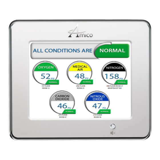
- Page 1 Operating & Maintenance Manual Alert-3 LCD Alarm v2.7 1ST FLOOR 2ND FLOOR 3RD FLOOR ROOM 37 ROOM 12 ROOM 25 MAINTEN EXT 302 4TH FLOOR 5TH FLOOR ROOM 47 ROOM 58...
-
Page 2: Table Of Contents
Contents User Responsibility Introduction Features Description of the Alarm Shipment Details The Alarm Back Box The Frame Assembly Description of Modules System Power Supply LCD Module Sensor Module Installation Guide 7 - 11 The Alarm Back Box For Local Sensor Only Standing Pressure Test Sensor 7 - 8... - Page 3 Contents Troubleshooting 20 - 21 Appendix A Wiring Diagram: LCD Board Appendix B Wiring Diagram: Auto-Switch Power Supply Appendix C Wiring Diagram: LCD Display Board - Alarm Buzzer Appendix D Wiring Diagram: LCD Display Board - Local Sensor Appendix E Wiring Diagram: LCD Display Board - Remote Sensor Appendix F Wiring Diagram: LCD Display Board - Master Module...
-
Page 4: User Responsibility
Should such repair or replacement become necessary, please contact Amico Corporation or their distributors. Alarms should not be altered without prior written or verbal approval from Amico Corporation or a factory trained service technician. Failure to comply will void all warranty on the alarm. -
Page 5: Features
• LCD Alarm available in 1 to 8 gases Description of the Alarm SHIPMENT DETAILS When you receive an Alert-3 LCD alarm from Amico Corporation, the package will consist of three main sections: the Alarm Back Box, Sensors and the Frame Assembly. THE ALARM BACK BOX The Alarm Back Box contains an auto-switchable power supply with an ON/OFF switch, a built-in fuse and terminal blocks (115 to 220 VAC - 50 to 60 Hz). -
Page 6: Description Of Modules
Description of Modules The Alert-3 LCD Alarm is a high technology microprocessor based module: COMMON TO ALL ALARMS AC Supply L - Live 115 to 220 VAC N - Neutral G - Ground Ground SYSTEM POWER SUPPLY Toggle Switch Fuse (1 AMPw) The System Power Supply has been pre-installed into the back box assembly. -
Page 7: Installation Guide
NOTE: PRESSURE ON SENSORS ARE NOT TO EXCEED 250 PSI FOR PRESSURE SENSORS AND 30 INHG FOR VACUUM SENSORS. MAKE SURE THAT THERE ARE NO MOISTURE, WATER OR BURS INSIDE THE PIPELINE BEFORE PROCEEDING WITH THE PRESSURE TEST. Alert-3 sensor operating pressure range: Mid Pressure (0 to 99 psi) -
Page 8: Remote
INSTALLATION. WHEN INSTALLATION IS COMPLETED AND ALARM IS READY TO USE, PEEL OFF THE LCD SCREEN PROTECTOR. CAUTION: The microprocessor circuitry on the ALERT-3 alarm contains sophisticated integrated semiconductors. DO NOT TOUCH any of the components on the board. Static discharge can cause the modules to malfunction or become damaged. -
Page 9: System Power Supply
The location of gases displayed on screen is dependant upon which sensor channel each individual gas is connected to. The display below indicates which sensor channel corresponds to each location the gas will be displayed on the LCD screen. www.amico.com... -
Page 10: Local
COM (Common), NO (Normally Open) or NC (Normally Closed), using the diagram in Appendix A. See Appendix G for contact rating. Once the sensors are connected and the power has been switched on, use the following steps to setup the LCD Alarm. Amico Corporation... -
Page 11: Lcd Display Setup
SCREEN AND PUSH BUTTON FROM DAMAGING. CAUTION: 1. To protect from static electricity, ensure to discharge body static before installing the Medical Gas Alarm and sensors. 2. Do not use impact screw driver. 3. Warranty void if push button is broken. www.amico.com... -
Page 12: Programming Gas Locations
Screen. • If the gas location text does not appear on the screen, repeat step #6. If the problem persists, contact Amico Corporation for further assistance. 9. Once the text is visible on the LCD Alarm, leave the SDHC Card in the slot for approximately 1 minute in order for the information to be completely uploaded onto the alarm, and then proceed to remove the card. - Page 13 PROGRAMMING GAS LOCATIONS FOR 4 GASES OUT OF 6 GAS Skip two lines 1ST FLOOR 3RD FLOOR ROOM 37 ROOM 12 MAINTEN EXT 302 Notepad File 4TH FLOOR 6TH FLOOR ROOM 65 ROOM 47 ENGINEER EXT 225 Updated Display on LCD Alarm www.amico.com...
- Page 14 PROGRAMMING GAS LOCATIONS TO SKIP LINES Skip one line Skip two lines Skip one line 1ST FLOOR 2ND FLOOR ROOM 25 Notepad File 4TH FLOOR 5TH FLOOR 6TH FLOOR ROOM 65 ROOM 58 ENGINEER EXT 225 Updated Display on LCD Alarm Amico Corporation...
-
Page 15: Clear/Erase Programming Gas Location Text
1ST FLOOR 2ND FLOOR 3RD FLOOR ROOM 37 ROOM 12 ROOM 25 MAINTEN EXT 302 4TH FLOOR 5TH FLOOR 6TH FLOOR ROOM 65 ROOM 47 ROOM 58 ENGINEER EXT 225 NOTE: A SD Card is not needed for this process. www.amico.com... -
Page 16: Model Numbers
The “L” Defines the Language: Oxygen English (NFPA) Medical Air English (CSA/ISO) = MedVac French (CSA/ISO) = Nitrous Oxide Spanish (NFPA) Nitrogen Carbon Dioxide WAGD (NFPA) AGSS (CSA/ISO) Instrument Air NOTE: EACH ALERT-3 SENSOR COMES WITH AN A2P-PIPE Amico Corporation... -
Page 17: Spare Part Numbers
Description A3-MAN-ALM-ENG Alert-3 Alarm Manual English A2P-POWER-V2 Power Supply Module A2P-BOXASS-3LCD Alarm Back Box Assembly 3-Station A3P-FRMASS-E-LCD Alert-3 Alarm Frame Assembly LCD-English (ISO) A3P-FRMASS-U-LCD Alert-3 Alarm Frame Assembly LCD-US (NFPA) A2P-PIPE Pressure Module Pipe Assembly A3P-DEMO-CASE Alert-3 Demo Alarm www.amico.com... -
Page 18: Demand Check Valves
A2P-CONKIT-SQUCOG-1 Conv For 1 Gas Squire Cogswell/ Product A2P-CONKIT-TRITEC-1 Conv 1 Gas Tri-Tech/Beconmedes/PB Mega A3P-LCD-FILLER-4 Alert-3 Filler Frame 4 - Station - White Colour A3P-LCD-FILLER-5 Alert-3 Filler Frame 5 - Station - White Colour A3P-LCD-FILLER-7 Alert-3 Filler Frame 7 - Station - White Colour... -
Page 19: Dimensions
[30.48] [31.75] [22.23] 0.75 [19.05] NOTE: LCD Alarm itself is 8 lbs. Each sensor is 1 lb. ALERT-3 SENSOR 6" - 8" [0.1m - 0.2 m] #22 gauge 1.88 1/2”-14 NPSM [13] stranded, shielded and twisted pair [48] cable supplied... - Page 20 Disconnect the DC power cable from the LCD system power supply to LCD alarm is module and then reconnect. If audible alarm loose still persists, replace the LCD frame assembly. Faulty push button (broken) Replace the LCD frame assembly. Amico Corporation...
- Page 21 Press setup and select button to program all connected sensors (see pg. 11, step 9). Faulty sensors Replace sensors. FACTORY DEFAULT SETTING GAS Mid Pressure 60 psi 40 psi Vacuum 32 inHg 12 inHg High Pressure 195 psi 140 psi www.amico.com...
- Page 22 2. To protect from static electricity, ensure to discharge body static before installing the Medical Gas Alarm and Sensors. 3. Warranty void if push button is broken or if the frame assembly is disassembled. Amico Corporation...
- Page 23 LCD Module Blue (5 VDC) Orange (15 VDC) CAUTION: 1. Verify that power has been switched off prior to working on the alarm 2. Risk of electric shock, disconnect power at the circuit breaker before removing power supply shield www.amico.com...
- Page 24 Remote Buzzer NC COM NO 12V GND NOTE: AMICO RECOMMENDS MAX. 50 FT. TO POWER UP BUZZER FROM ALARM PANEL TO POWER UP THE BUZZER. MORE THAN 50 FT., A A3P-POWER-V4 IS REQUIRED TO SUPPLY VOLTAGE FOR THE ALARM BUZZER.
- Page 25 Black Orange (15 VDC) NOTE: Do not ground the shield drain wire at sensor or inside alarm panel back box CAUTION: To protect from static electricity, ensure to discharge body static before installing the Medical Gas Alarm and sensors www.amico.com...
- Page 26 Black Orange (15 VDC) Note: For multiple sensors, a multi-conductor twisted pair cable can be used. NOTE: For multiple sensors, a multi- conductor #22 gauge stranded, shielded and twisted pair cable ONLY must be used Amico Corporation...
- Page 27 Master Module Module Blue (5 VDC) #22 Gauge twisted Black (Ground) Black pair shielded cable 5,000' [1,500m] max. Dry Contact to Amico Master Orange (15 VDC) Module or Building Management System Source Equipement Source Note: Jumper any unused points Equipment on the Master module.
- Page 28 For Master Alarm, source equipment signal wires must be connected to normally-closed dry contacts. No electrical voltage can be present and contacts must be closed during normal equipment operation. When contacts are open; an alarm condition will be activated. Amico Corporation...
- Page 29 The following rules along with references to this manual’s schematics clarify wiring requirements. Two conductor cables (must be #22 gauge stranded, shielded and twisted pair cable type) are required for each Gas Sensor module to the Gas Input board. www.amico.com...
- Page 32 Amico Corporation | 85 Fulton Way, Richmond Hill, ON L4B 2N4, Canada 600 Prime Place, Hauppauge, NY 11788, USA Toll Free Tel: 1.877.462.6426 | Tel: 905.764.0800 | Fax: 905.764.0862 Email: info@amico.com | www.amico.com ACP-OPER-MAINT-ALERT3-LCD-ALRM 04.27.2022...
Need help?
Do you have a question about the Alert-3 and is the answer not in the manual?
Questions and answers