Table of Contents
Advertisement
NetApp™ Hardware
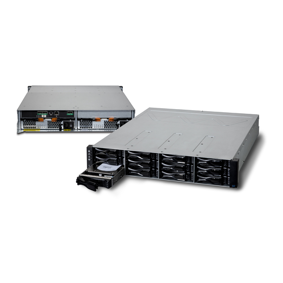
E2600 Controller-Drive Tray and Related Drive Trays
NetApp, Inc.
495 East Java Drive
Sunnyvale, CA 94089 U.S.A.
Telephone: +1 (408) 822-6000
Fax: +1 (408) 822-4501
Support telephone: +1 (888) 4-NETAPP
Document comments: doccomments@netapp.com
Information Web: http://www.netapp.com
Part number: 53014-00, Rev. A
March 2012
Advertisement
Table of Contents

Related Manuals for NetApp E2600


Summary of Contents for NetApp E2600
- Page 1 NetApp™ Hardware E2600 Controller-Drive Tray and Related Drive Trays NetApp, Inc. 495 East Java Drive Sunnyvale, CA 94089 U.S.A. Telephone: +1 (408) 822-6000 Fax: +1 (408) 822-4501 Support telephone: +1 (888) 4-NETAPP Document comments: doccomments@netapp.com Information Web: http://www.netapp.com Part number: 53014-00, Rev. A...
- Page 2 NetApp assumes no responsibility or liability arising from the use of products described herein, except as expressly agreed to in writing by NetApp. The use or purchase of this product does not convey a license under any patent rights, trademark rights, or any other intellectual property rights of NetApp.
- Page 3 Topio, vFiler, VFM, Virtual File Manager, VPolicy, WAFL, Web Filer, and XBB are trademarks or registered trademarks of NetApp, Inc. in the United States, other countries, or both. IBM, the IBM logo, and ibm.com are trademarks or registered trademarks of International Business Machines Corporation in the United States, other countries, or both.
-
Page 5: Table Of Contents
Procedure – Installing and Configuring Switches ..........27 Step 3 - Installing the Host Bus Adapters for the E2600 Controller-Drive Tray......29 Key Terms . - Page 6 Things to Know – Drive Trays with the E2600 Controller-Drive Tray ......82...
- Page 7 Things to Know – LEDs on the E2600 Controller-Drive Tray .......
- Page 8 E2600 Controller-Drive Tray ........
-
Page 9: Step 1 - Preparing For An E2600 Controller-Drive Tray Installation
Step 1 - Preparing for an E2600 Controller-Drive Tray Installation Storage arrays for 6-Gb/s SAS drives consist of a E2600 controller-drive tray model and one or more drive trays in a cabinet. Use this document to install one of the following E2600 controller-drive tray models and all necessary drive trays... - Page 10 A maximum of 96 drives that you can upgrade to 192. The upgrade is E2612 controller-drive a Premium feature. tray or E2624 Any combination of E2600 controller-drive trays attached to DE1600 controller-drive tray drive trays or DE5600 drive trays, not to exceed a maximum of 96 (or without a host interface 192) drive slots or 8 total trays in the storage array.
-
Page 11: Key Terms
(ESM) A canister in the drive tray that monitors the status of the components. An ESM also serves as the connection point to transfer data between the drive tray and the controller. E2600 Controller-Drive Tray Installation Guide... -
Page 12: Small Form-Factor Pluggable (Sfp) Transceiver
Depending on the power supply limitations of your cabinet, you might need to install more than one cabinet to accommodate the different components of the E2600 storage array. Refer to the installation guide for your cabinet for instructions on installing the cabinet. -
Page 13: E2600 Configuration Cables And Connectors
Host with Fibre Channel host bus adapters (HBAs) (optional) Host with iSCSI HBAs (optional) or a network interface card (optional) Host with SAS HBAs (optional) E2600 Configuration Cables and Connectors Table 4 Cables and Connectors Included with the Item Controller-Drive Tray or Drive Trays AC power cords. - Page 14 1-Gb/s iSCSI connections. For information about out-of-band storage array management, see the description for "Deciding on the Management Method" in Initial Configuration and Software Installation PDF on the SANtricity™ ES Storage Manager Installation DVD. E2600 Controller-Drive Tray Installation Guide...
- Page 15 This cable is used for support only. You do not need to connect it during initial installation. DB9-to-PS2 adapter cable This cable adapts the DB9 connector on commercially available serial cables to the PS2 connector on the controller. E2600 Controller-Drive Tray Installation Guide...
-
Page 16: Product Dvds
Tray Labels Help you to identify cable connections and lets you more easily trace cables from one tray to another A cart Holds the tray and components A mechanical lift (optional) A Phillips screwdriver E2600 Controller-Drive Tray Installation Guide... -
Page 17: Things To Know - Sfp Transceivers, Fiber-Optic Cables, Copper Cables, And Sas Cables
WARNING (W03) Risk of exposure to laser radiation – Do not disassemble or remove any part of a Small Form-factor Pluggable (SFP) transceiver because you might be exposed to laser radiation. E2600 Controller-Drive Tray Installation Guide... - Page 18 Figure 2 1-Gb/s iSCSI Cable Connection Active SFP Transceiver Copper Cable with RJ-45 Connector Figure 3 Copper Fibre Channel Cable Connection Copper Fibre Channel Cable Passive SFP Transceiver Figure 4 SAS Cable Connection SAS Cable SFF-8088 Connector E2600 Controller-Drive Tray Installation Guide...
-
Page 19: Things To Know - Taking A Quick Glance At The Hardware In A E2612 Controller-Drive Tray Or A E2624 Controller-Drive Tray Configuration
Figure 5 E2612 Controller-Drive Tray – Front View End Cap Standby Power LED End Cap Power LED End Cap Over-Temperature LED End Cap Service Action Required LED End Cap Locate LED Drive Canister E2600 Controller-Drive Tray Installation Guide... - Page 20 Ethernet Link Active LED Ethernet Link Rate LED Ethernet Connector 2 10. Host SFF-8088 Connector 2 (Native) 11. Host Link 2 Fault LED 12. Host Link 2 Active LED 13. Base Host SFF-8088 Connector 1 E2600 Controller-Drive Tray Installation Guide...
- Page 21 SFF-8088 Host Interface Card Connector 3 Host Interface Card Link 4 Up LED Host Interface Card Link 4 Active LED SFF-8088 Host Interface Card Connector 4 ESM Expansion Fault LED ESM Expansion Active LED Expansion SFF-8088 Port Connector E2600 Controller-Drive Tray Installation Guide...
- Page 22 Host Interface Card Link 3 Up LED Host Interface Card Link 3 Active LED iSCSI Host Interface Card Connector 3 Host Interface Card Link 4 Up LED Host Interface Card Link 4 Active LED iSCSI Host Interface Card Connector 4 E2600 Controller-Drive Tray Installation Guide...
- Page 23 System integrators, resellers, system administrators, or users of the controller-drive tray can install the drives. NOTE In a simplex configuration, the Controller Air Blocker must be kept in place to ensure proper air flow to the components within the canister. E2600 Controller-Drive Tray Installation Guide...
- Page 24 Figure 15 DE1600 Drive Tray or DE5600 Drive Tray with AC Power Option – Rear View ESM A Canister Host Connector 1 Host Connector 2 Seven-Segment Display Indicators Serial Connector Ethernet Connector Expansion Port SFF-8088 Connector Power-Fan Canister Power Connector 10. Power Switch 11. ESM B Canister E2600 Controller-Drive Tray Installation Guide...
- Page 25 DC MAINS must be disconnected by removing all power connectors (item 4 below) from the power supplies. Supply (Negative), Brown Wire, -48 VDC Return (Positive), Blue Wire Ground, Green/Yellow Wire DC Power Connector E2600 Controller-Drive Tray Installation Guide...
-
Page 26: Things To Know - Taking A Quick Glance At The Hardware In A E2660 Controller-Drive Tray Configuration
Figure 17 E2660 Controller-Drive Tray – Front View Drive Drawer End Cap Locate LED End Cap Service Action Required LED End Cap Over-Temperature LED End Cap Power LED End Cap Standby Power LED E2600 Controller-Drive Tray Installation Guide... - Page 27 25. Controller A Service Action Required LED 26. Controller A Service Action Allowed LED 27. Battery Service Action Required LED 28. Battery Charging LED 29. Power Canister 30. Power Canister AC Power LED 31. Power Canister Service Action Required LED E2600 Controller-Drive Tray Installation Guide...
- Page 28 SFF-8088 Host Interface Card Connector 3 Host Interface Card Link 4 Up LED Host Interface Card Link 4 Active LED SFF-8088 Host Interface Card Connector 4 ESM Expansion Fault LED ESM Expansion Active LED Expansion SFF-8088 Port Connector E2600 Controller-Drive Tray Installation Guide...
- Page 29 10. Host Interface Card Link 6 Up LED 11. Host Interface Card Link 6 Active LED 12. FC Host Interface Card Connector 6 13. ESM Expansion Fault LED 14. ESM Expansion Active LED 15. Expansion SFF-8088 Port Connector E2600 Controller-Drive Tray Installation Guide...
- Page 30 10. Host Interface Card Link 6 Up LED 11. Host Interface Card Link 6 Active LED 12. iSCSI Host Interface Card Connector 6 13. ESM Expansion Fault LED 14. ESM Expansion Active LED 15. Expansion SFF-8088 Port Connector E2600 Controller-Drive Tray Installation Guide...
-
Page 31: For Additional Information On The E2600 Controller-Drive Tray Configuration
For Additional Information on the E2600 Controller-Drive Tray Configuration Refer to the Storage System Site Preparation Guide on the SANtricity ES Storage Manager Installation DVD for information about the installation requirements of the various E2600 storage array components. E2600 Controller-Drive Tray Installation Guide... - Page 32 E2600 Controller-Drive Tray Installation Guide...
-
Page 33: Step 2 - Installing And Configuring The Switches
Fibre Channel network protocols. The switches in the following table are certified for use with an E2600 storage array and an E2660 storage array, which both use SANtricity ES Storage Manager Version 10.83. - Page 34 If required, make the appropriate configuration changes for each switch that is connected to the storage array. Refer to the switch’s documentation for information about how to install the switch and how to use the configuration utilities that are supplied with the switch. E2600 Controller-Drive Tray Installation Guide...
-
Page 35: Procedure - Installing And Configuring Switches
E2600 Controller-Drive Tray” on option to ON. page 29. Cisco Change the In-Order Delivery (IOD) option to ON. “Installing the Host Bus Adapters for the E2600 Controller-Drive Tray” on McData page 29. QLogic PowerConnect E2600 Controller-Drive Tray Installation Guide... - Page 36 E2600 Controller-Drive Tray Installation Guide...
-
Page 37: Step 3 - Installing The Host Bus Adapters For The E2600 Controller-Drive Tray
Things to Know – Host Bus Adapters and Ethernet Network Interface Cards The E2600 controller-drive tray supports dual 6-Gb/s SAS host connections and optional host interface cards (HICs) for dual 6-Gb/s SAS, four 1-Gb/s iSCSI, two 10-Gb iSCSI, and four 8-Gb/s FC connections. The connections on a host must match the type (SAS HBAs for SAS, FC HBAs for FC, or iSCSI HBAs or Ethernet network interface cards [NICs] for iSCSI) of the HICs to which you connect them. - Page 38 Associated HBAs Wide Name ICTENGINEERING Vendor x, Model y (dual port) 37:38:39:30:31:32:33:32 37:38:39:30:31:32:33:33 Vendor a, Model y (dual port) 42:38:39:30:31:32:33:42 42:38:39:30:31:32:33:44 ICTFINANCE Vendor a, Model b (single port) 57:38:39:30:31:32:33:52 Vendor x, Model b (single port) 57:38:39:30:31:32:33:53 E2600 Controller-Drive Tray Installation Guide...
-
Page 39: Step 4 - Installing The E2600 Controller-Drive Tray
NOTE Make sure that the combined power requirements of your trays do not exceed the power capacity of your cabinet. Procedure – Installing the E2600 Controller-Drive Tray Figure 24 Airflow Direction Through and Clearance Requirements for the E2600 Controller-Drive Tray with 12 Drives 76-cm (30-in.) clearance in front of the cabinet 61-cm (24-in.) clearance behind the cabinet... - Page 40 Figure 25 Airflow Direction Through and Clearance Requirements for the E2600 Controller-Drive Tray with 24 Drives 76-cm (30-in.) clearance in front of the cabinet 61-cm (24-in.) clearance behind the cabinet WARNING (W08) Risk of bodily injury – Two persons are required to safely lift the component.
- Page 41 Figure 27 on page 34). The rear of the controller-drive tray slides into the slots on the mounting rails. Figure 26 Securing the E2600 Controller-Drive Tray with 12 Drives to the Cabinet Screws Mounting Holes E2600 Controller-Drive Tray Installation Guide...
-
Page 42: Procedure - Installing The E2660 Controller-Drive Tray
Figure 27 Securing the E2600 Controller-Drive Tray with 24 Drives to the Cabinet Screws NOTE The rear of the controller-drive tray contains two controllers. The top of the controller-drive tray is the side with the labels. Secure the screws in the top mounting holes and the bottom mounting holes on each side of the controller-drive tray. - Page 43 WARNING (W15) Risk of bodily injury – An empty tray weighs approximately 56.7 kg (125 lb). Three persons are required to safely move an empty tray. If the tray is populated with components, a mechanized lift is required to safely move the tray. E2600 Controller-Drive Tray Installation Guide...
- Page 44 Position the mounting rails in the cabinet. Figure 30 Positioning the Mounting Rails in the Cabinet Screws for Securing the Mounting Rail to the Cabinet (Front) Screws for Securing the Mounting Rail to the Cabinet (Rear) Existing Tray Industry Standard Cabinet E2600 Controller-Drive Tray Installation Guide...
- Page 45 Insert two M5 screws through the rear of the cabinet, and screw them into the captured nuts in the rear flange in the mounting rail. Tighten the adjustment screws on the mounting rail. Repeat substep through substep to install the second mounting rail. E2600 Controller-Drive Tray Installation Guide...
- Page 46 Insert two M5 screws through the rear of the cabinet, and screw them into the captured nuts in the rear flange in the mounting rail. Tighten the adjustment screws on the mounting rail. Repeat substep through substep to install the second mounting rail. E2600 Controller-Drive Tray Installation Guide...
- Page 47 WARNING (W15) Risk of bodily injury – An empty tray weighs approximately 56.7 kg (125 lb). Three persons are required to safely move an empty tray. If the tray is populated with components, a mechanized lift is required to safely move the tray. E2600 Controller-Drive Tray Installation Guide...
- Page 48 Figure 34 Removing an Enclosure Lift Handle from the Controller-Drive Tray Pull the thumb latch away from the controller-drive tray to detach the hook. Shift the handle down to release the other four hooks. Move the handle away from the drive tray. E2600 Controller-Drive Tray Installation Guide...
- Page 49 EIA support rail and engage the bottom captured nuts in the mounting rail. Tighten the screws. Repeat substep a for the second flange. Figure 35 Attaching the Front of the Controller-Drive Tray Four Screws for Securing the Front of the Controller-Drive Tray E2600 Controller-Drive Tray Installation Guide...
- Page 50 Figure 36 Removing the Fan Canister from the Controller-Drive Tray Fan Canister Handle 13. Use the fan canister handle to pull the fan canister out of the controller-drive tray. E2600 Controller-Drive Tray Installation Guide...
- Page 51 NOTE After the controller-drive tray is installed, there should be seven screws on each side (right and left) of the cabinet. NOTE Make sure that each drive drawer in the controller-drive tray is securely fastened to ensure proper air flow to the drives. E2600 Controller-Drive Tray Installation Guide...
- Page 52 16. Attach the bezel onto the front of the controller-drive tray. NOTE If the E2660 controller-drive tray needs to have drives installed, refer to Steps to Install – Drives on the DE6600 Drive Tray on page 77. E2600 Controller-Drive Tray Installation Guide...
-
Page 53: Step 5 - Connecting The E2600 Controller-Drive Tray To The Hosts
Step 5 - Connecting the E2600 Controller-Drive Tray to the Hosts Key Terms direct topology A topology that does not use a switch. switch topology A topology that uses a switch. topology The logical layout of the components of a computer system or network and their interconnections. Topology deals with questions of what components are directly connected to other components from the standpoint of being able to communicate. -
Page 54: Procedure - Connecting Host Cables On A E2600 Controller-Drive Tray
Form-factor Pluggable (SFP) transceiver because you might be exposed to laser radiation. Procedure – Connecting Host Cables on a E2600 Controller-Drive Tray NOTE Make sure that you have installed the HBAs. Refer to the documentation for the HBAs for information about how to install the HBA and how to use the supplied configuration utilities. - Page 55 Figure 41 Direct Topology – One Host Connected to a Single Controller Host HBA 1 or NIC 1 HBA 2 or NIC 2 Host Port 1 Host Port 2 Controller A E2600 Controller-Drive Tray Installation Guide...
- Page 56 Figure 42 Direct Topology – Two Hosts Connected to a Single Controller Host HBA 1 or NIC 1 HBA 2 or NIC 2 Host Port 1 Host Port 2 Controller A E2600 Controller-Drive Tray Installation Guide...
- Page 57 Figure 43 Switch Topology – Two Hosts Connected to a Single Controller Through a Switch Host HBA 1 or NIC 1 HBA 2 or NIC 2 Host Port 1 Host Port 2 Controller A E2600 Controller-Drive Tray Installation Guide...
- Page 58 Figure 44 Direct Topology – One Host and a Dual Controller-Drive Tray Host HBA 1 or NIC 1 HBA 2 or NIC 2 Host Port 1 Host Port 2 Controller A Controller B E2600 Controller-Drive Tray Installation Guide...
- Page 59 Figure 45 Direct Topology – Two Hosts and a Dual Controller-Drive Tray for Maximum Redundancy Hosts HBA 1 or NIC 1 HBA 2 or NIC 2 Host Port 1 Host Port 2 Controller A Controller B E2600 Controller-Drive Tray Installation Guide...
- Page 60 Figure 46 Mixed Topology – Two Hosts and a Dual Controller-Drive Tray Hosts HBA 1 or NIC 1 HBA 2 or NIC 2 Host Port 1 Host Port 2 Controller A Controller B E2600 Controller-Drive Tray Installation Guide...
- Page 61 The host name and the HBA port (for direct topology) — The switch name and the port (for fabric topology) — The controller ID (for example, controller A) — The host channel ID (for example, host channel 1) — E2600 Controller-Drive Tray Installation Guide...
- Page 62 Example label abbreviation – Assume that a cable is connected between port 1 in HBA 1 of a host named Engineering and host channel 1 of controller A. A label abbreviation could be as follows. Repeat step on page through step on page for each controller and host channel that you intend to use. E2600 Controller-Drive Tray Installation Guide...
-
Page 63: Step 6 - Installing The Drive Trays For The E2600 Controller-Drive Tray Configurations
Step 6 - Installing the Drive Trays for the E2600 Controller-Drive Tray Configurations Things to Know – General Installation of Drive Trays with the E2600 Controller-Drive Tray NOTE If you are installing the drive tray in a cabinet with other trays, make sure that the combined power requirements of the drive tray and the other trays do not exceed the power capacity of your cabinet. - Page 64 NOTE Fans pull air through the tray from front to back across the drives. Lower the feet on the cabinet to keep the cabinet from moving. Remove the drive tray and all contents from the shipping carton. E2600 Controller-Drive Tray Installation Guide...
- Page 65 If you are installing the mounting rails above an existing tray, position the mounting rails directly above — the tray. If you are installing the mounting rails below an existing tray, allow 8.8-cm (3.5-in.) vertical clearance for — the drive tray. E2600 Controller-Drive Tray Installation Guide...
- Page 66 Mounting Rails Clip for Securing the Rear of the Drive Tray Place the mounting rail inside the cabinet, and extend the mounting rail until the flanges on the mounting rail touch the inside of the cabinet. E2600 Controller-Drive Tray Installation Guide...
- Page 67 Insert two M5 screws through the rear of the cabinet and into the captured nuts in the rear flange in the mounting rail. Tighten the screws. Tighten the adjustment screws on the mounting rail. Repeat substep through substep to install the second mounting rail. E2600 Controller-Drive Tray Installation Guide...
- Page 68 The holes in the drive tray sheet metal for the rear hold-down screws align with the captured nuts in the — side of the mounting rails. Figure 53 Sliding the Drive Tray into the Clip on the Mounting Rail Mounting Rail Clip Partial View of the Drive Tray Rear Sheet Metal Mounting Holes E2600 Controller-Drive Tray Installation Guide...
- Page 69 Tighten the screw. Repeat substep a for the second flange. Figure 54 Attaching the Front of the DE1600 Drive Tray Screws for Securing the Front of the Drive Tray E2600 Controller-Drive Tray Installation Guide...
- Page 70 Secure the side of the drive tray to the mounting rails by performing these substeps: Insert one M5 screw through the side sheet metal of the drive tray into the captured nut on the side of the mounting rail. Tighten the screw. Repeat substep for the other side. E2600 Controller-Drive Tray Installation Guide...
- Page 71 Gently press on the bottom of the end cap until it snaps into place over the retainer on the bottom of the drive tray mounting flange. Figure 56 Attaching the End Caps to the DE1600 Drive Tray Hinge Tab Retainer E2600 Controller-Drive Tray Installation Guide...
-
Page 72: Procedure - Installing Drives In The De1600 Drive Trays And The De5600 Drive Trays
ATTENTION Risk of equipment malfunction – To avoid exceeding the functional and environmental limits, install only drives that have been provided or approved by the original manufacturer. Drives might be shipped but not installed. System integrators, resellers, system administrators, or users can install the drives. E2600 Controller-Drive Tray Installation Guide... - Page 73 Push the drive handle to the right (DE1600 drive tray) or down (DE5600 drive tray) to lock the drive securely in place. Figure 58 Installing a Drive in the DE1600 Drive Tray Drive Handle E2600 Controller-Drive Tray Installation Guide...
-
Page 74: Things To Know - General Installation Of Drive Trays With The E2660 Controller-Drive Tray
WARNING (W15) Risk of bodily injury – An empty tray weighs approximately 56.7 kg (125 lb). Three persons are required to safely move an empty tray. If the tray is populated with components, a mechanized lift is required to safely move the tray. E2600 Controller-Drive Tray Installation Guide... -
Page 75: Steps To Install -De6600 Drive Tray
Figure 60 Drive Tray Airflow and Clearance Requirements 81 cm (32 in.) clearance in front of the cabinet 61 cm (24 in.) clearance behind the cabinet NOTE Fans pull air through the drive tray from front to back across the drives. E2600 Controller-Drive Tray Installation Guide... - Page 76 (two to a side) as shown in the following figure. Set the drive tray aside. Figure 61 DE6600 Drive Tray with Drive Tray Handles (Two on Each Side) E2600 Controller-Drive Tray Installation Guide...
- Page 77 To attach the long mounting rails to the cabinet, perform these substeps: Make sure that the adjustment screws on the mounting rail are loose so that the mounting rail can extend or contract as needed. E2600 Controller-Drive Tray Installation Guide...
- Page 78 Tighten the adjustment screws on the mounting rail. Repeat substep through substep to install the second mounting rail. h. Insert one M5 screw through the front of the mounting rail. You use this screw to attach the drive tray to the cabinet. E2600 Controller-Drive Tray Installation Guide...
- Page 79 Insert two M5 screws through the rear of the cabinet, and screw them into the captured nuts in the rear flange in the mounting rail. Tighten the adjustment screws on the mounting rail. Repeat substep through substep to install the second mounting rail. E2600 Controller-Drive Tray Installation Guide...
- Page 80 Insert one M5 screw through the front of the mounting rail. This screw attaches the drive tray to the cabinet. Figure 65 Short Adjustable Mounting Rail Attached to the Cabinet Cabinet Mounting Holes on the Front EIA Support Rail E2600 Controller-Drive Tray Installation Guide...
- Page 81 Figure 66 Removing an Enclosure Lift Handle from the Drive Tray Pull the thumb latch away from the drive tray to detach the hook. Shift the handle down to release the other four hooks. Move the handle away from the drive tray. E2600 Controller-Drive Tray Installation Guide...
- Page 82 EIA support rail and engage the bottom captured nuts in the mounting rail. Tighten the screws. Repeat substep a for the second flange. Figure 67 Attaching the Front of the Drive Tray Four Screws for Securing the Front of the Drive Tray E2600 Controller-Drive Tray Installation Guide...
- Page 83 Figure 68 Removing the Fan Canister from the Drive Tray Fan Canister Handle 13. Use the fan canister handle to pull the fan canister out of the drive tray. E2600 Controller-Drive Tray Installation Guide...
- Page 84 NOTE After the drive tray is installed, there should be seven screws on each side (right and left) of the cabinet. NOTE Make sure that each drive drawer in the drive tray is securely fastened to ensure proper air flow to the drives. E2600 Controller-Drive Tray Installation Guide...
-
Page 85: Steps To Install - Drives On The De6600 Drive Tray
The long edge of each drive should touch the drive next to it. To maintain a uniform airflow across all drive drawers, the drive tray must be configured with a minimum of 20 drives, with four drives in the front row of each of the five drive drawers. E2600 Controller-Drive Tray Installation Guide... - Page 86 Figure 71 Levers on the Drive Drawer Levers to Release the Drive Drawer Pull on the extended levers to pull the drive drawer out to its full extension without removing it from the drive tray. E2600 Controller-Drive Tray Installation Guide...
- Page 87 Figure 72 Raised Drive Handle Align the two raised buttons on each side over the matching gap in the drive channel on the drawer. Figure 73 Side View of Drive with Raised Handle Raised Buttons E2600 Controller-Drive Tray Installation Guide...
- Page 88 The drive drawer must be completely closed to prevent excess airflow, which has the potential to damage the drives. Continue onto the next drive drawer, repeating step through step for each drive drawer in the configuration. E2600 Controller-Drive Tray Installation Guide...
-
Page 89: Step 7 - Connecting The E2600 Controller-Drive Tray To The Drive Trays
Things to Know – E2600 Controller-Drive Tray On the E2600 controller-drive tray, each controller has a pair of levers with handles for removing the controller from the controller-drive tray. One of these handles on each controller is located next to a host connector. The close spacing between the handle and the host connector might make it difficult to remove a cable that is attached to the host connector. -
Page 90: Things To Know - Drive Trays With The E2600 Controller-Drive Tray
Things to Know – Drive Tray Cabling Configurations – Simplex System The following figure shows an example of cable configurations from the simplex E2600 controller-drive tray to either a DE1600 drive tray or a DE5600 drive tray. Use this example as a guide to connect cables in your storage array. -
Page 91: Things To Know - Drive Tray Cabling Configurations - Duplex System
Figure 79 Controller-Drive Tray Above the Drive Tray Figure 80 Controller-Drive Tray Between Two Drive Trays E2600 Controller-Drive Tray Installation Guide... - Page 92 Figure 81 Controller-Drive Tray with Three Drive Trays E2600 Controller-Drive Tray Installation Guide...
-
Page 93: Procedure - Connecting The De1600 Drive Trays And The De5600 Drive Trays
Use the following table to determine the number of SAS cables that you need. Table 13 Drive Tray Cables Number of Drive Trays that You Plan to Connect to the Number of Cables Required Controller-Drive Tray E2600 Controller-Drive Tray Installation Guide... - Page 94 To each end of the cables, attach a label with this information: The controller ID (for example, controller A) — The ESM ID (for example, ESM A) — The ESM connector (In or Out) — The drive tray ID — E2600 Controller-Drive Tray Installation Guide...
-
Page 95: Things To Know - E2660 Controller-Drive Tray
NOTE To maintain data access in the event of the failure of a controller, an ESM, or a drive channel, you must connect a drive tray or a string of drive trays to both drive channels on a redundant path pair. E2600 Controller-Drive Tray Installation Guide... -
Page 96: Things To Know - Drive Trays With The E2660 Controller-Drive Tray
The figures in this topic show examples of cable configurations from the controller-drive tray to the drive trays. Use these examples as guides to connect cables in your storage array. Figure 85 Controller-Drive Tray Above the Drive Tray E2600 Controller-Drive Tray Installation Guide... -
Page 97: Procedure - Connecting The De6600 Drive Tray
Insert one end of the cable into the SAS expansion connector on the controller in slot A in the controller-drive tray. Insert the other end of the cable into the connector with an up arrow on the ESM in slot A in the drive tray. Are you adding more drive trays? E2600 Controller-Drive Tray Installation Guide... - Page 98 A. That is, the last drive tray in the chain from controller A must be the first drive tray in the chain from controller B. E2600 Controller-Drive Tray Installation Guide...
-
Page 99: Step 8 - Connecting The Ethernet Cables
Connect one end of an Ethernet cable into the Ethernet port 1 on controller A. Connect the other end to the applicable network connection. Repeat step 1 through step 2 for controller B. E2600 Controller-Drive Tray Installation Guide... - Page 100 E2600 Controller-Drive Tray Installation Guide...
-
Page 101: Step 9 - Connecting The Power Cords
Step 9 - Connecting the Power Cords The E2600 controller-drive tray, the DE1600 drive tray, and the DE5600 drive tray can have either standard power connections to an AC power source or the optional connections to a DC power source (–48 VDC). -
Page 102: Procedure - Connecting Ac Power Cords
Have a qualified service person connect the other end of the DC power connector cables to the DC power plant equipment as follows: Connect the brown –48 VDC supply wire to the negative terminal. Connect the blue return wire to the positive terminal. Connect the green/yellow ground wire to the ground terminal. E2600 Controller-Drive Tray Installation Guide... -
Page 103: Step 10 - Turning On The Power And Checking For Problems In A E2600 Controller-Drive Tray Configuration
Procedure – Turning On the Power to the Storage Array and Checking for Problems in a E2600 Controller-Drive Tray Configuration NOTE You must turn on the power to all of the connected drive trays before you turn on the power for the controller-drive tray. -
Page 104: Things To Know - Leds On The E2600 Controller-Drive Tray
Things to Know – LEDs on the E2600 Controller-Drive Tray The following topics provide details on the LEDs found on the E2600 controller-drive tray. LEDs on the Left End Cap Figure 89 LEDs on the Left End Cap Controller-Drive Tray Locate LED... - Page 105 An error has Normal status. Action Required occurred. Drive Service Blue The drive canister The drive canister Action Allowed can be removed cannot be removed safely from the safely from the controller-drive tray. controller-drive tray. E2600 Controller-Drive Tray Installation Guide...
- Page 106 The link is up (LED blinks The link is not active. 1 Link Active LED when there is activity). Ethernet Connector Green There is a 100BASE-T rate. There is a 10BASE-T rate. 2 Link Rate LED E2600 Controller-Drive Tray Installation Guide...
- Page 107 Cache Active LED Green Cache is active.* Cache is inactive or the controller canister has been removed from the controller-drive tray. * After an AC power failure, this LED blinks while cache offload is in process. E2600 Controller-Drive Tray Installation Guide...
- Page 108 LEDs on the Controller Canister Host Interface Card Subplates NOTE The following figure shows an iSCSI host interface card (HIC), but the E2600 controller-drive tray also supports a four-connector FC HIC and a two-connector SAS HIC with comparable LEDs. Figure 92 LEDs on the Controller Canister Host Interface Card Subplates...
- Page 109 (HIC), which also can be a four-port FC HIC or a two-port SAS HIC. LEDs on the Power-Fan Canister Figure 93 LEDs on the Power-Fan Canister Standby Power LED Power-Fan DC Power LED Power-Fan Service Action Allowed LED Power-Fan Service Action Required LED Power-Fan AC Power LED E2600 Controller-Drive Tray Installation Guide...
-
Page 110: Things To Know - Leds On The E2660 Controller-Drive Tray
The following topics provide details on the LEDs found on the E2660 controller-drive tray. LEDs on the Left End Cap Figure 94 LEDs on the Left End Cap Controller-Drive Tray Locate LED Service Action Required LED Controller-Drive Tray Over-Temperature LED Power LED Standby Power LED E2600 Controller-Drive Tray Installation Guide... - Page 111 Host Link 2 Service Action Allowed LED Battery Service Action Required LED 10. Battery Charging LED 11. Controller Service Action Allowed LED 12. Controller Service Action Required LED 13. Cache Active LED 14. Seven-Segment Tray ID E2600 Controller-Drive Tray Installation Guide...
- Page 112 Controller Service Blue The controller canister can The controller canister Action Allowed be removed safely from the cannot be removed safely controller-drive tray. from the controller-drive tray. E2600 Controller-Drive Tray Installation Guide...
- Page 113 LEDs on the Controller Canister Host Interface Card Subplates NOTE The figure immediately below shows an iSCSI host interface card (HIC), but the E2600 controller-drive tray also supports a four-connector FC HIC and a two-connector SAS HIC with comparable LEDs.
- Page 114 Expansion connector. "LEDs on the Controller Canister Host Interface Card Subplates" on page shows the four-port iSCSI host interface card (HIC), which can also be a four-port FC HIC or a two-port SAS HIC. E2600 Controller-Drive Tray Installation Guide...
- Page 115 Power-Fan Service Amber A fault exists within the Normal status. Action Required power-fan canister. Power-Fan AC Green AC power to the power-fan AC power to the power-fan Power canister is present. canister is not present. E2600 Controller-Drive Tray Installation Guide...
-
Page 116: Things To Know - General Behavior Of The Leds On The E2600 Controller-Drive Tray
Things to Know – General Behavior of the LEDs on the E2600 Controller-Drive Tray Table 25 LED Symbols and General Behavior Location Symbol Function (Canisters) Power Power-fan On – The controller has power. Interconnect-battery Off – The controller does not have power. - Page 117 For example, if some of the cache memory dual in-line memory modules (DIMMs) are missing in a controller, error code L8 appears in the diagnostic display (see “Things to Know – Supported Diagnostic Lock-Down Codes on the Seven-Segment Display”). E2600 Controller-Drive Tray Installation Guide...
-
Page 118: Things To Know - Service Action Allowed Leds
The Service Action Allowed LED automatically comes on or goes off as conditions change. In most cases, the Service Action Allowed LED comes on when the Service Action Required (Fault) LED comes on for a canister. E2600 Controller-Drive Tray Installation Guide... -
Page 119: Things To Know - Leds On The De1600 Drive Tray And The De5600 Drive Tray
Drive Tray Power Green Power is present. Power is not present. Drive Tray Green The drive tray is in Standby The drive tray is not in Standby Power Power mode. Standby Power mode. E2600 Controller-Drive Tray Installation Guide... - Page 120 Drive Service Action Drive State (Green) Required LED (Amber) Power is not applied. Normal operation – The power is turned on, but drive I/O activity is not occurring. Normal operation – Drive I/O activity is occurring. Blinking E2600 Controller-Drive Tray Installation Guide...
- Page 121 Host Link 1 Active Green At least one of the four A link error has occurred. PHYs in the In port is working, and a link exists to the device connected to the Host In connector. E2600 Controller-Drive Tray Installation Guide...
- Page 122 Seven-Segment Green See note. Not applicable. Tray ID NOTE: For more information about the seven-segment tray IDs, see Things to Know – Seven Segment Component Failure Identifications for the E2600 Controller-Drive Tray on page 123. E2600 Controller-Drive Tray Installation Guide...
- Page 123 Power-Fan Service Amber A fault exists within the Normal status. Action Required power-fan canister. Power-Fan AC Green AC power to the power-fan AC power to the power-fan Power canister is present. canister is not present. E2600 Controller-Drive Tray Installation Guide...
-
Page 124: Things To Know - Leds On The De6600 Drive Tray
Drive Tray Power Green Power is present. Power is not present. Drive Tray Green The drive tray is in Standby The drive tray is not in Standby Power Power mode. Standby Power mode. E2600 Controller-Drive Tray Installation Guide... - Page 125 Power to the ESM is Power is not present to the present. ESM. Seven-Segment Green For more information, see Not applicable. Tray ID “Things to Know – Seven-Segment Display for the Drive Trays” on page 128. E2600 Controller-Drive Tray Installation Guide...
- Page 126 AC power to the power AC power to the power canister is present. canister is not present. Figure 106 LEDs on the Fan Canister Fan Power LED Fan Service Action Required LED Fan Service Action Allowed LED E2600 Controller-Drive Tray Installation Guide...
-
Page 127: Leds On The De6600 Drive Drawers
Drive Drawer Blue The drive canister The drive canister Service Action can be removed cannot be Allowed safely from the removed safely drive drawer in the from the drive drive tray. drawer in the drive tray. E2600 Controller-Drive Tray Installation Guide... -
Page 128: Leds On The De6600 Drives
Service action required – A fault condition exists, and the drive is offline. LEDs on the DE6600 Drives Figure 107 LEDs on the DE6600 Drive Drive Service Action Allowed LED Drive Service Action Required LED E2600 Controller-Drive Tray Installation Guide... -
Page 129: General Behavior Of The Leds On The Drive Trays
Drive Tray Front bezel on the On – The temperature of the drive tray Over-Temperature drive tray has reached an unsafe condition. Off – The temperature of the drive tray is within operational range. E2600 Controller-Drive Tray Installation Guide... - Page 130 On – The cable is attached and at least above each one lane has a link-up status. expansion Off – The cable is not attached, or the connector cable is attached and all lanes have a link-down status. E2600 Controller-Drive Tray Installation Guide...
-
Page 131: Things To Know - Seven Segment Component Failure Identifications For The E2600 Controller-Drive Tray
Diagnostic LED (lower-digit decimal point) comes on when the display is used for diagnostic codes and goes off when the display is used to show the tray ID. Table 41 Sequence Code Definitions for the E2600 Controller-Drive Tray Category Code... - Page 132 2 A two-digit code that follows the category code with more specific information. 3 The plus (+) sign indicates that a two-digit code displays with the Diagnostic LED on. 4 No codes display, and the Diagnostic LED is off. E2600 Controller-Drive Tray Installation Guide...
-
Page 133: Things To Know - Lock-Down Codes For The Controller-Drive Tray
A mixed cache memory DIMMs condition has been detected, which results in a suspended controller state. Uncertified cache memory DIMM sizes have been detected, which result in a suspended controller state. The controller has locked down in a suspended state with limited symbol support. E2600 Controller-Drive Tray Installation Guide... -
Page 134: Things To Know - Seven-Segment Display Use Cases
OS+ bb+ blank- backup). The CPU temperature has exceeded the warning level. OS+ OH+ blank- Use Cases Repeating Sequence Use Case: Component failure when the controller is operational. Failed host interface card OS+ CF+ HX+ blank- E2600 Controller-Drive Tray Installation Guide... - Page 135 OE+ L2+ dash+ CF+ CX+ been detected. blank- Use Cases Repeating Sequence Use Case: The controller has been suspended as a result of persistent cache backup configuration errors. The write-protect switch is set during cache restore. OE+ LC+ blank- E2600 Controller-Drive Tray Installation Guide...
-
Page 136: Things To Know - Seven-Segment Display For The Drive Trays
ESM or the power supply. The midplane SBB VPD EEPROM cannot be accessed. The ESM canister is not valid for this drive tray. Drive port mapping tables are not found. An ESM Fibre Channel interface failure has occurred. E2600 Controller-Drive Tray Installation Guide... - Page 137 2A and 2B are not supported. Look for the SFP transceiver with the blinking amber LED, and remove it. A non-catastrophic hardware failure has occurred. The ESM is operating in a Degraded state. The ESM canister is incompatible with the drive tray firmware. E2600 Controller-Drive Tray Installation Guide...
- Page 138 E2600 Controller-Drive Tray Installation Guide...
-
Page 139: Regulatory Compliance Statements
NetApp, Inc. is not responsible for any radio or television interference caused by unauthorized modification of this equipment or the substitution or attachment of connecting cables and equipment other than those specified by NetApp. It is the user’s responsibility to correct interference caused by such unauthorized modification, substitution, or attachment. - Page 140 This Class A digital apparatus meets all requirements of the Canadian Interference-Causing Equipment Regulations. Cet appareil numérique de la classé A respecte toutes les exigences du Règlement sure le matèriel brouilleur du Canada. FCC-2 Regulatory Compliance Statement...
- Page 142 © Copyright 2012 NetApp, Inc. All rights reserved.
Need help?
Do you have a question about the E2600 and is the answer not in the manual?
Questions and answers