Table of Contents
Advertisement
Quick Links
Industrial Automation Headquarters
Delta Electronics, Inc.
Taoyuan Technology Center
No.18, Xinglong Rd., Taoyuan District,
Taoyuan City 33068, Taiwan
TEL: 886-3-362-6301 / FAX: 886-3-371-6301
Asia
Delta Electronics (Shanghai) Co., Ltd.
No.182 Minyu Rd., Pudong Shanghai, P.R.C.
Post code : 201209
TEL: 86-21-6872-3988 / FAX: 86-21-6872-3996
Customer Service: 400-820-9595
Delta Electronics (Japan), Inc.
Tokyo Office
Industrial Automation Sales Department
2-1-14 Shibadaimon, Minato-ku
Tokyo, Japan 105-0012
TEL: 81-3-5733-1155 / FAX: 81-3-5733-1255
Delta Electronics (Korea), Inc.
Seoul Office
1511, 219, Gasan Digital 1-Ro., Geumcheon-gu,
Seoul, 08501 South Korea
TEL: 82-2-515-5305 / FAX: 82-2-515-5302
Delta Energy Systems (Singapore) Pte Ltd.
4 Kaki Bukit Avenue 1, #05-04, Singapore 417939
TEL: 65-6747-5155 / FAX: 65-6744-9228
Delta Electronics (India) Pvt. Ltd.
Plot No.43, Sector 35, HSIIDC Gurgaon,
PIN 122001, Haryana, India
TEL: 91-124-4874900 / FAX : 91-124-4874945
Delta Electronics (Thailand) PCL.
909 Soi 9, Moo 4, Bangpoo Industrial Estate (E.P.Z),
Pattana 1 Rd., T.Phraksa, A.Muang,
Samutprakarn 10280, Thailand
TEL: 66-2709-2800 / FAX : 662-709-2827
Delta Energy Systems (Australia) Pty Ltd.
Unit 20-21/45 Normanby Rd., Notting Hill Vic 3168, Australia
TEL: 61-3-9543-3720
Americas
Delta Electronics (Americas) Ltd.
Raleigh Office
P.O. Box 12173, 5101 Davis Drive,
Research Triangle Park, NC 27709, U.S.A.
TEL: 1-919-767-3813 / FAX: 1-919-767-3969
Delta Greentech (Brasil) S/A
São Paulo Office
Rua Itapeva, 26 – 3˚ Andar - Bela Vista
CEP: 01332-000 – São Paulo – SP - Brasil
TEL: 55-11-3530-8642 / 55-11-3530-8640
Delta Electronics International Mexico S.A. de C.V.
Mexico Office
Vía Dr. Gustavo Baz No. 2160, Colonia La Loma,
54060 Tlalnepantla Estado de Mexico
TEL: 52-55-2628-3015 #3050/3052
*We reserve the right to change the information in this catalogue without prior notice.
DPM-093AB20-01
EMEA
Delta Electronics (Netherlands) BV
Eindhoven Office
De Witbogt 20, 5652 AG Eindhoven, The Netherlands
MAIL: Sales.IA.EMEA@deltaww.com
MAIL: Sales.IA.Benelux@deltaww.com
Delta Electronics (France) S.A.
ZI du bois Chaland 2 15 rue des Pyrénées,
Lisses 91056 Evry Cedex, France
MAIL: Sales.IA.FR@deltaww.com
Delta Electronics Solutions (Spain) S.L.U
Ctra. De Villaverde a Vallecas, 265 1˚ Dcha Ed.
Hormigueras – P.I. de Vallecas 28031 Madrid
C/Llull, 321-329 (Edifici CINC) | 22@Barcrelona, 08019 Barcelona
MAIL: Sales.IA.Iberia@deltaww.com
Delta Electronics (Italy) Srl
Ufficio di Milano Via Senigallia 18/2 20161 Milano (MI)
Piazza Grazioli 18 00186 Roma, Italy
MAIL: Sales.IA.Italy@deltaww.com
Delta Electronics (Germany) GmbH
Coesterweg 45, D-59494 Soest, Germany
MAIL: Sales.IA.DACH@deltaww.com
Delta Energy Systems LLC (CIS)
Vereyskaya Plaza II, office 112 Vereyskaya str.
17 121357 Moscow, Russia
MAIL: Sales.IA.RU@deltaww.com
Delta Greentech Elektronik San. Ltd. Sti. (Turkey)
Serifali Mah. Hendem Cad. Kule Sok. No: 16-A
34775 Umraniye / Istanbul
MAIL: Sales.IA.Turkey@deltaww.com
Delta Energy Systems AG (Dubai BR)
P.O. Box 185668, Gate 7, 3rd Floor, Hamarain Centre,
Dubai, United Arab Emirates
MAIL: Sales.IA.MEA@deltaww.com
2018/08/30
Advertisement
Table of Contents

Related Manuals for Delta DPM-C501L


Summary of Contents for Delta DPM-C501L
- Page 1 909 Soi 9, Moo 4, Bangpoo Industrial Estate (E.P.Z), Pattana 1 Rd., T.Phraksa, A.Muang, Samutprakarn 10280, Thailand Delta Greentech Elektronik San. Ltd. Sti. (Turkey) Serifali Mah. Hendem Cad. Kule Sok. No: 16-A TEL: 66-2709-2800 / FAX : 662-709-2827 34775 Umraniye / Istanbul Delta Energy Systems (Australia) Pty Ltd.
- Page 4 DPM-C501L Operation Manual Revision History Ve r s i o n R e v i s i o n D a t e T h e f i r s t v e r s i o n w a s p u b l i s h e d .
-
Page 5: Table Of Contents
DPM-C501L Operation Manual Table of Contents Chapter 1 Product Introduction Preface ....................1-2 Overview ................... 1-2 Safety Precautions ................1-3 Chapter 2 Product Specifications Electrical Characteristics ..............2-2 Communications ................2-3 Operating the Display ................ 2-4 2.3.1 Menu Tree ..................2-5 Dimensions .................. - Page 6 4.2.6 Set up Reset (RST) ................ 4-5 4.2.7 Digital Input (DI) ................4-5 4.2.8 Relay Output (RO) ................. 4-6 4.2.9 Edit the Password (PWD) ..............4-8 4.2.10 Meter Information (INFO) ............... 4-9 Power Analysis Values ............... 4-9 4.3.1 Total Harmonic Distortion Measurement ..........4-9 Chapter 5 Parameters and Funcitons Overview of Parameters ..............
-
Page 7: Chapter 1 Product Introduction
Chapter 1 Product Introduction Table of Contents Preface ....................1-2 Overview ................... 1-2 Safety Precautions ................1-3 1 - 1... -
Page 8: Preface
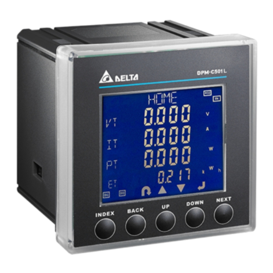
Delta Electronics website (http://www.delta.com.tw/ia/). Overview The DPM-C501L is equipped with a large, back-lit LCD display that displays up to four lines of information. 1 - 2... -
Page 9: Safety Precautions
C ha pt er 1 P r o d u c t I n t r o d u c t i o n Safety Precautions Installation Notes Install the power meter according to instructions on the manual. Use appropriate personal protective equipment (PPE) and follow safe electrical work practices. - Page 10 D P M - C 5 0 1 L O p e r a t i o n M a n u a l MEMO 1 - 4...
-
Page 11: Chapter 2 Product Specifications
Chapter 2 Product Specifications Table of Contents Electrical Characteristics ..............2-2 Communications .................. 2-3 Operating the Display ................2-4 2.3.1 Menu Tree ..................2-5 Dimensions ..................2-6 2 - 1... -
Page 12: Electrical Characteristics
D P M - C 5 0 1 L O p e r a t i o n M a n u a l Electrical Characteristics Measurement Accuracy Voltage, current ± 0.5% Real power ± 0.5% Electric Electric quantities Real power, reactive ±... -
Page 13: Communications
C h a p t e r 2 P r o d u c t Sp e c i f i c a t i o n Ambient operating temperature -20–50°C (-4–122°F) Storage temperature -30–60 °C (-22–140°F) Environment Relative Humidity 5–95% RH Altitude Below 2000 meters... -
Page 14: Operating The Display
D P M - C 5 0 1 L O p e r a t i o n M a n u a l Operating the Display Enable / Disable UP Key Screen Title DOWN Key Load percentage NEXT Key Item Operating status Enable / disable... -
Page 15: Menu Tree
C h a p t e r 2 P r o d u c t Sp e c i f i c a t i o n 2.3.1 Menu Tree Display Menu Tree You can always use this button to return to HOME. -
Page 16: Dimensions
D P M - C 5 0 1 L O p e r a t i o n M a n u a l Dimensions Front Unit: mm Back: 2 - 6... -
Page 17: Chapter 3 Installation
Chapter 3 Installation Table of Contents Installation ..................3-2 3.1.1 Installation Environment ..............3-2 3.1.2 Installation Notes ................3-2 Basic Checks ..................3-4 Wiring ....................3-4 3.3.1 Wiring Diagrams ................3-4 3.3.2 Communication Characteristics ............3-6 3 - 1... -
Page 18: Installation
D P M - C 5 0 1 L O p e r a t i o n M a n u a l 3.1 Installation 3.1.1 Installation Environment Keep the product in the shipping carton before installation. Store the product properly when it is not to be used for an extended period of time to retain the warranty coverage. - Page 19 C h a p t e r 3 I n s ta l l a t i o n Installation This multi-functional power meter package comes with securing brackets for easier mounting and removing. The mounting hole dimension is 92x92 mm (see the figure below) Slide the securing bracket into the hole and then push the meter in.
-
Page 20: Basic Checks
D P M - C 5 0 1 L O p e r a t i o n M a n u a l 3.2 Basic Checks Items Contents Regularly check for mounting looseness where the power meter and device are connected. - Page 21 C h a p t e r 3 I n s ta l l a t i o n Connection 3PH3W, Δ connection, 3 CT, No PT 3PH3W, Δ connection, 2 CT, No PT 3PH3W, Δ connection, 3 CT, 2 PT 3PH4W, Y connection, 3 CT, No PT 3PH4W, Y connection, 3 CT, 3 PT 3PH4W, Y connection, 2 CT, 3 PT...
-
Page 22: Communication Characteristics
D P M - C 5 0 1 L O p e r a t i o n M a n u a l DI/DO Connection The following table lists the symbols used in the diagram. Symbol Current Terminal Voltage Description Grounding... -
Page 23: Chapter 4 Operation
Chapter 4 Operation Table of Contents General Operation ................4-2 4.1.1 Setting Menu ................. 4-2 Setups ....................4-3 4.2.1 Set up the Password (PASS) ............4-3 4.2.2 Set up Communication (COM)............4-3 4.2.3 Set up the System (SYS) ..............4-4 4.2.4 Set up the Current Transformer (CT) .......... -
Page 24: General Operation
DP M- C5 0 1L O pe r a t io n M a nu a l 4.1 General Operation Use the UP and DOWN keys to switch among setting pages. Use the BACK or INDEX keys to go back to HOME page. Note 1: Use the BACK key in the HOME page to enter the setting page. -
Page 25: Setups
C h a p t e r 4 O p e r a t i o n Reversed apparent energy page (-VAH): Reversed apparent energy measured by the power meter, including reversed apparent energy (SH). Total harmonic current distortion page (THD I): Current harmonic distortion measured by the power meter, including phase A current (A), phase B current (B), and phase C current (C) harmonic distortion;... -
Page 26: Set Up The System (Sys)
DP M- C5 0 1L O pe r a t io n M a nu a l Note: You can go back to the previous setting item by pressing BACK anytime, whether you have completed or canceled the setting. 4.2.3 Set up the System (SYS) ... -
Page 27: Set Up The Potential Transformer (Pt)
C h a p t e r 4 O p e r a t i o n 4.2.5 Set up the Potential Transformer (PT) Voltage for the primary-side potential transformer; 1– 65535 V, 1 V is default. Voltage for the secondary-side potential transformer; 1–9999 V, 1 V is default. ... -
Page 28: Relay Output (Ro)
DP M- C5 0 1L O pe r a t io n M a nu a l Press NEXT until the option starts blinking. Use UP and DOWN to select ON or OFF. Press NEXT to save the setting and then set the next digital input. When the option starts blinking, use UP and DOWN to select ON or OFF. - Page 29 C h a p t e r 4 O p e r a t i o n If the under phase voltage alarm is triggered, the corresponding relay Under phase closes. If the under phase voltage alarm voltage alarm is canceled, the corresponding relay opens.
-
Page 30: Edit The Password (Pwd)
DP M- C5 0 1L O pe r a t io n M a nu a l If the digital input 3 receives a higher potential, the corresponding relay closes. Digital input 3 If the digital input 1 receives a lower potential, the corresponding relay opens. -
Page 31: Meter Information (Info)
C h a p t e r 4 O p e r a t i o n 4.2.10 Meter Information (INFO) Model: C501L Firmware version: 1XXXX Firmware release date: XXXXYYZZ (XXXX: year, YY: month, ZZ: day) 4.3 Power Analysis Values 4.3.1 Total Harmonic Distortion Measurement The total harmonic distortion (THD) is a measurement of the harmonic distortion and is defined as the ratio between the power of the harmonic frequencies above the base frequency and the power of the base frequency. - Page 32 DP M- C5 0 1L O pe r a t io n M a nu a l MEMO 4 - 1 0...
-
Page 33: Chapter 5 Parameters And Funcitons
Chapter 5 Parameters and Functions Table of Contents Overview of Parameters ..............5-2 5 - 1... -
Page 34: Overview Of Parameters
DP M- C5 0 1L O pe r a t io n M a nu a l 5.1 Overview of Parameters MODBUS Data Address Data Read (R) / Item Range Unit Size Type Write (W) Modicom (byte) Format 0. System Parameters: 0001 – 00FF Year: 00–99 Year, 40002... - Page 35 Ch a pt er 5 P ar am eter s a nd F unc t io ns 1: 3φ3W 2: 1φ2W 3: 1φ3W 40015 Primary CT (A) 1 – 9999 uint 0:1A 40016 Secondary CT (A) word 1:5A 40017 Primary PT 1 –...
- Page 36 DP M- C5 0 1L O pe r a t io n M a nu a l 0: None 40026 Stop bit 1: Even word 2: Odd 40027 Stop bit 0: 1 word 40028 Modbus address 0 – 255 word 0: None 1: Reset to factory default 40029...
- Page 37 Ch a pt er 5 P ar am eter s a nd F unc t io ns voltage value exceeding 40055 this value triggers alarm) 40056 Reserved 40057 Dropout setpoint (line voltage value below this 0.000 – 99999.999 float 40058 value clears alarm) 40059 Reserved...
- Page 38 DP M- C5 0 1L O pe r a t io n M a nu a l 40073 Reserved Alarm – Under Voltage L-N 0: Disable 40074 Alarm enable word 1: Enable 40075 Pickup setpoint (phase voltage value below this 0.000 –...
- Page 39 Ch a pt er 5 P ar am eter s a nd F unc t io ns triggered) 40105 Reserved 40106 Dropout setpoint (total reactive power value below 0.000 – 99999.999 float kVAR 40107 this value clears alarm) 40108 Reserved Alarm –...
- Page 40 DP M- C5 0 1L O pe r a t io n M a nu a l 40178 Reserved Alarm – Under Frequency 0: Disable 40179 Alarm enable word 1: Enable 40180 Pickup setpoint (frequency value below this value 0.0000 – 99.9999 float 40181 triggers alarm)
- Page 41 Ch a pt er 5 P ar am eter s a nd F unc t io ns 40270 40271 Average line voltage 0.000 – 99999.999 float 40272 40273 Phase A voltage unbalance 0.00 – 99.99 float 40274 40275 Phase B voltage unbalance 0.00 – 99.99 float 40276 40277...
- Page 42 DP M- C5 0 1L O pe r a t io n M a nu a l 40294 40295 Three–phase average 0.000 – 99999.999 float current 40296 40297 Neutral line current 0.000 – 99999.999 float 40298 40299 Phase A current unbalance 0.00 – 99.99 float 40300 40301...
- Page 43 Ch a pt er 5 P ar am eter s a nd F unc t io ns 40318 factor of phase A (positive: lag; negative: lead) 40319 Total displacement power 0.00000 – 1.00000 float factor of phase B (positive: lag; negative: lead) 40320 40321 Total displacement power...
- Page 44 DP M- C5 0 1L O pe r a t io n M a nu a l 40342 power 40343 Instantaneous apparent 0.000 – 99999.999 float power of phase A 40344 40345 Instantaneous apparent 0.000 – 99999.999 float power of phase B 40346 40347 Instantaneous apparent...
- Page 45 Ch a pt er 5 P ar am eter s a nd F unc t io ns 40378 phase C current 40379 Total harmonic distortion for 0.000 – 999.999 float neutral line current 40380 40381 Total harmonic distortion for 0.000 – 999.999 float phase A voltage 40382...
- Page 46 DP M- C5 0 1L O pe r a t io n M a nu a l 40516 Date: 1–31 word Date Hour: 00–23 Hour, 40517 byte Time of maximum A–B line Minute Minute: 00–59 voltage 40518 Second: 00–59 word Second 40519 Maximum B–C line voltage 0.000 –...
- Page 47 Ch a pt er 5 P ar am eter s a nd F unc t io ns Hour: 00–23 Hour, 40535 byte Time of maximum phase A Minute Minute: 00–59 voltage 40536 Second: 00–59 word Second 40537 Maximum phase B voltage 0.000 – 99999.999 float 40538 Year: 00–99...
- Page 48 DP M- C5 0 1L O pe r a t io n M a nu a l current Minute: 00–59 Minute 40554 Second: 00–59 word Second 40555 Maximum phase B current 0.000 – 99999.999 float 40556 Year: 00–99 Year, 40557 byte Date of maximum phase B Month...
- Page 49 Ch a pt er 5 P ar am eter s a nd F unc t io ns 40572 Second: 00–59 word Second 40573 Maximum frequency value 0.0000 – 99.9999 float 40574 Year: 00–99 Year, 40575 byte Date of maximum Month Month: 1–12 frequency value 40576...
- Page 50 DP M- C5 0 1L O pe r a t io n M a nu a l 40591 Maximum total reactive 0.000 – 99999.999 float kVAR power 40592 Year: 00–99 Year, 40593 byte Date of maximum total Month Month: 1–12 reactive power 40594 Date: 1–31...
- Page 51 Ch a pt er 5 P ar am eter s a nd F unc t io ns 40775 Minimum B–C line voltage 0.000 – 99999.999 float 40776 Year: 00–99 Year, 40777 byte Date of minimum B–C line Month Month: 1–12 voltage 40778 Date: 1–31...
- Page 52 DP M- C5 0 1L O pe r a t io n M a nu a l 40794 Year: 00–99 Year, 40795 byte Date of minimum phase B Month Month: 1–12 voltage 40796 Date: 1–31 word Date Hour: 00–23 Hour, 40797 byte Time of minimum phase B...
- Page 53 Ch a pt er 5 P ar am eter s a nd F unc t io ns Year: 00–99 Year, 40813 byte Date of minimum phase B Month Month: 1–12 current 40814 Date: 1–31 word Date Hour: 00–23 Hour, 40815 byte Time of minimum phase B Minute...
- Page 54 DP M- C5 0 1L O pe r a t io n M a nu a l value Month: 1–12 Month 40832 Date: 1–31 word Date Hour: 00–23 Hour, 40833 byte Time of minimum frequency Minute Minute: 00–59 value 40834 Second: 00–59 word Second 40835...
- Page 55 Ch a pt er 5 P ar am eter s a nd F unc t io ns 40850 Date: 1–31 word Date Hour: 00–23 Hour, 40851 byte Time of minimum total Minute Minute: 00–59 reactive power 40852 Second: 00–59 word Second 40853 Minimum total apparent 0.000 –...
- Page 56 DP M- C5 0 1L O pe r a t io n M a nu a l voltage Year: 00–99 Year, 41045 byte Alarm date of over line Month Month: 1–12 voltage 41046 Date: 1–31 word Date Hour: 00–23 Hour, 41047 byte Alarm time of over line...
- Page 57 Ch a pt er 5 P ar am eter s a nd F unc t io ns Minute: 00–59 41060 Second: 00–59 word Second 0: Cleared Alarm status of under 41061 word voltage 1: Triggered Alarm times of under phase 41062 1–255 word...
- Page 58 DP M- C5 0 1L O pe r a t io n M a nu a l Year: 00–99 Year, 41087 byte Alarm date of over reactive Month Month: 1–12 energy 41088 Date: 1–31 word Date Hour: 00–23 Hour, 41089 byte Alarm time of over reactive Minute...
- Page 59 Ch a pt er 5 P ar am eter s a nd F unc t io ns 41150 Second: 00–59 word Second 0: Cleared Alarm status of power 41151 word factor (lag) 1: Triggered Alarm times of power factor 41152 1–255 word times...
- Page 60 DP M- C5 0 1L O pe r a t io n M a nu a l 1: Enable 0: Disable 41419 Setting of digital input #3 word 1: Enable 0: Disable 41420 Setting of digital input #4 word 1: Enable Alarms: 0: Disable 1: Over current...
- Page 61 Ch a pt er 5 P ar am eter s a nd F unc t io ns 1: High 255: Disable 0: Low 1: High 41426 Status of digital input #2 word 255: Disable 0: Low 1: High 41427 Status of digital input #3 word 255: Disable 0: Low...
- Page 62 DP M- C5 0 1L O pe r a t io n M a nu a l MEMO 5 - 3 0...
-
Page 63: Chapter 6 Error Codes
Chapter 6 Error Codes Table of Contents Error Codes ..................6-2 6 - 1... - Page 64 D P M - C 5 0 1 L O p e r a t i o n M a n u a l 6.1 Error Codes When an error occurs during operation, the power monitor sends an error code through Modbus. The following table lists the error codes and causes.
-
Page 65: Appendix A Accessories
12 A Appendix A Accessories Table of Contents DCT1000 Series ...................A-2 DCT2000 Series ...................A-4 A - 1... -
Page 66: Dct1000 Series
D P M - C 5 0 1 L O p e r a t i o n M a n u a l When measured current is higher than the rated specification for the device, use of an external current transformer (CT) is necessary. - Page 67 A pp e nd ix A Ac c es s o r i es Model Dimension (mm) Number External Dimension: DCT-S301C 90 x 40 x 111 DCT-S211C Size of Opening: 21 x 32 DCT-S221C DCT-S231C External Dimension: DCT-S241C 116.5 x 52 x 147 DCT-S251C Size of Opening: 50 x 80 DCT-S261C...
-
Page 68: Dct2000 Series
D P M - C 5 0 1 L O p e r a t i o n M a n u a l External Dimension: DCT-S291C 186.5 x 52 x 252 Size of Opening: 81 x 160.5 DCT-S2A1C DCT-S2B1C A.2 DCT2000 Series Electromagnetic Compatibility: UL, UL2808. - Page 69 A pp e nd ix A Ac c es s o r i es Model Dimension (mm) Number External Dimension: DCT-S201B 90 x 40 x 110 Size of Opening: 20 x 30 DCT-S211B DCT-S221B External Dimension: DCT-S231B 115 x 57 x 158 DCT-S241B Size of Opening: 50 x 80...
- Page 70 D P M - C 5 0 1 L O p e r a t i o n M a n u a l MEMO A - 6...
Need help?
Do you have a question about the DPM-C501L and is the answer not in the manual?
Questions and answers