Delta DVP-EX2 Operation Manual
Hide thumbs
Also See for DVP-EX2:
- Operation manual (785 pages) ,
- Operation manual (20 pages) ,
- Operation manual (1006 pages)

Related Manuals for Delta DVP-EX2


Summary of Contents for Delta DVP-EX2
- Page 1 Digitized Automation for a Changing World DVP-ES2 / EX2 / EC5 / SS2 / SA2 / SX2 / SE / SE2 & TP Operation Manual - Programming www.deltaww.com...
- Page 2 DVP-ES2/EX2/SS2/SA2/SX2/SE/SE2&TP Operation Manual Programming Revision History I s s u e D e s c r i p t i o n o f C h a n g e s D a t e T h e f i r s t e d i t i o n i s i s s u e d . 2 0 1 0 / 0 2 / 2 6 T h e s e c o n d e d i t i o n i s i s s u e d .
- Page 3 I s s u e D e s c r i p t i o n o f C h a n g e s D a t e C h a p t e r 3 . 8 D e t a i l e d I n s t r u c t i o n E x p l a n a t i o n : I n c r e a s e e x p l a n a t i o n s o f D S PA i n s t r u c t i o n , a n d a d d f l o a t i n g - p o i n t c o n t a c t t y p e c o m p a r i s o n i n s t r u c t i o n s F L D = , F L D >...
- Page 4 I s s u e D e s c r i p t i o n o f C h a n g e s D a t e 1 . T h e t i m e r i n t e r r u p t s I 8 0 5 - I 8 9 9 a r e a d d e d t o C h a p t e r 2 .
- Page 5 I s s u e D e s c r i p t i o n o f C h a n g e s D a t e 4 . I n s e c t i o n B . 2 . 4 , t h e d e s c r i p t i o n s o f C R # 0 a n d C R # 2 0 - C R # 2 6 a r e u p d a t e d .
- Page 6 I s s u e D e s c r i p t i o n o f C h a n g e s D a t e D 6 0 0 0 - D 6 0 6 3 . 6 .
- Page 7 I s s u e D e s c r i p t i o n o f C h a n g e s D a t e 5 . S e c t i o n 2 . 1 6 : u p d a t e d t h e f o l l o w i n g c o n t e n t s : M 1 0 7 7 f o r r e a l - t i m e c l o c k , D 1 0 2 1 f o r a d j u s t m e n t o n i n p u t t e r m i n a l r e s p o n s e t i m e , M 1 0 3 3 f o r o u t p u t s t a t e l a t c h e d i n S TO P m o d e , C O M 2 i n C O M p o r t...
- Page 8 I s s u e D e s c r i p t i o n o f C h a n g e s D a t e C R # 2 6 , a n d C R # 8 8 t o C R # 9 3 i n s e c t i o n s f r o m B .
- Page 9 I s s u e D e s c r i p t i o n o f C h a n g e s D a t e 2 . U p d a t e d t h e c o n t e n t s i n t h e s p e c i f i c a t i o n o f r e a l t i m e c l o c k a n d s p e c i a l I / O m o d u l e s i n s e c t i o n s 2 .
- Page 10 I s s u e D e s c r i p t i o n o f C h a n g e s D a t e 9 . A d d e d E C 5 S e r i e s p r o d u c t i n f o r m a t i o n i n c h a p t e r s 4 a n d 5 .
- Page 11 I s s u e D e s c r i p t i o n o f C h a n g e s D a t e S e c t i o n 2 . 1 4 : u p d a t e d D 1 0 0 2 , D 1 0 2 1 , D 1 0 3 6 , D 1 0 3 8 , D 1 0 8 6 , D 1 0 8 7 , D 11 0 9 , D 111 0 , D 1111 , D 11 2 1 , D 11 6 7 , D 11 6 9 , D 11 7 6 - D 11 7 9 , D 1 2 2 2 - D 1 2 3 1 , D 1 2 4 9 , D 1 2 5 0 , D 1 2 5 2 , D 1 2 5 3 ,...
- Page 12 DVP-ES2/EX2/EC5/SS2/SA2/SX2/SE&TP Operation Manual Programming Contents 1 PLC Concepts PLC Scan Method ..................1-2 Current Flow ..................... 1-3 NO Contact, NC Contact ................1-3 PLC Registers and Relays ............... 1-3 Ladder Logic Symbols ................1-3 1.5.1 Creating a PLC Ladder Program ............. 1-5 1.5.2 LD / LDI (Load NO contact / Load NC contact) .......
- Page 13 3.6.19 Contact Type Comparison Instructions ........3-590 3.6.20 Specific Bit Control Instructions ............ 3-600 3.6.21 Floating-Point Contact Type Comparison Instructions ....3-610 3.6.22 Delta Special CANopen Communication Instructions ....3-614 3.6.23 Module Instructions ..............3-660 4 Communications Communication Ports ................4-2 Communication Protocol ASCII mode ............
- Page 14 Command Code ..................4-13 4.5.1 Command Code: 01, Read Status of Contact (Input point X is not included) ..................4-13 4.5.2 Command Code: 02, Read Status of Contact (Input point X is included) ..................4-14 4.5.3 Command Code: 03, Read Content of Register (T, C, D) ..... 4-15 4.5.4 Command Code: 05, Force ON/OFF single contact ......
- Page 15 Object Dictionary ..................7-37 Appendix A Installing the USB Driver in Windows 7 ............ A-2 Installing the USB in Windows 8 .............. A-4 Installing the USB Driver in Windows 10 ..........A-7 Notes on Utilizing USB Communication ........... A-9 Appendix B Specifications for an Ethernet PLC/Module ..........
- Page 16 module (+24VDC) ..............D-3 D.1.3 Current consumption of a special input/output module (+24VDC) ... D-3 D.1.4 Current consumption of a left-side high-speed special module (+24VDC) ................D-4 D.1.5 Calculating the maximum current consumed by a system ....D-4 Appendix E DVP Series Slim Type Special Modules ...........
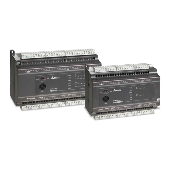
- Page 17 T h e D V P s e r i e s P L C s a r e l i s t e d b e l o w. S e r i e s M o d e l n a m e D V P 1 6 E S 2 0 0 R , D V P 1 6 E S 2 0 0 T , D V P 2 4 E S 2 0 0 R , D V P 2 4 E S 2 0 0 T , D V P 3 2 E S 2 0 0 R , D V P 3 2 E S 2 0 0 T , D V P 3 2 E S 2 1 1 T , D V P 4 0 E S 2 0 0 R , D V P 4 0 E S 2 0 0 T , D V P 6 0 E S 2 0 0 R , D V P 6 0 E S 2 0 0 T ,...
- Page 18 PLC Concepts This chapter introduces basic and advanced concepts of ladder logic, which is the mostly adopted programming language of PLC. Users familiar with the PLC concepts can move to the next chapter for further programming concepts. However, for users not familiar with the operating principles of PLC, please refer to this chapter to get a full understanding of PLC concepts.
- Page 19 D V P - E S 2 / E X 2 / E C 5 / S S 2 / S A 2 / S X 2 / S E / S E 2 & T P O p e r a t i o n M a n u a l - P r o g r a m m i n g PLC Scan Method PLC utilizes a standard scan method when evaluating user program.
- Page 20 1 . P L C C o n c e p t s Current Flow Ladder logic follows a left to right principle. In the example below, the current flows through paths started from either X0 or X3. Reverse Current When a current flows from right to left, which makes a reverse current logic, an error will be detected when compiling the program.
- Page 21 D V P - E S 2 / E X 2 / E C 5 / S S 2 / S A 2 / S X 2 / S E / S E 2 & T P O p e r a t i o n M a n u a l - P r o g r a m m i n g Bit, word, or double word memory used for counting and has coil, contact, and register in it.
- Page 22 1 . P L C C o n c e p t s Ladder Diagram Explanation Instruction Available Devices Structure Multiple output branches None Output coil Y, M, S Step ladder Basic instructions and API Basic and Application instructions. Please refer to instruction chapter 3 Instruction Set Inverse logic...
- Page 23 D V P - E S 2 / E X 2 / E C 5 / S S 2 / S A 2 / S X 2 / S E / S E 2 & T P O p e r a t i o n M a n u a l - P r o g r a m m i n g 1.5.2 LD / LDI (Load NO contact / Load NC contact) LD or LDI starts a row or block LD instruction...
- Page 24 1 . P L C C o n c e p t s 1.5.9 ORB (Connect block in parallel) ORB instruction connects a block in parallel with another block ORB instruction 1.5.10 MPS, MRD, MPP (Branch instructions) These instructions provide a method to create multiplexed output branches based on current result stored by MPS instruction.
- Page 25 D V P - E S 2 / E X 2 / E C 5 / S S 2 / S A 2 / S X 2 / S E / S E 2 & T P O p e r a t i o n M a n u a l - P r o g r a m m i n g previous step is completed, therefore it forms a sequential control process similar to SFC (Sequential Function Chart) mode.
- Page 26 1 . P L C C o n c e p t s Conversion between Ladder Diagram and Instruction List Mode Ladder Diagram Instruction block block Block in series block Block in parallel The output AN I continues based on status of Multiple outputs...
- Page 27 D V P - E S 2 / E X 2 / E C 5 / S S 2 / S A 2 / S X 2 / S E / S E 2 & T P O p e r a t i o n M a n u a l - P r o g r a m m i n g Fuzzy Syntax Generally, the ladder diagram programming is conducted according to the “up to down and left to right”...
- Page 28 1 . P L C C o n c e p t s Block combination should be made on top of the circuit. Parallel connection with empty device is not allowed.. Parallel connection with empty device is not allowed. No device in the middle block. Devices and blocks in series should be horizontally aligned Label P0 should be at the first row of the...
- Page 29 D V P - E S 2 / E X 2 / E C 5 / S S 2 / S A 2 / S X 2 / S E / S E 2 & T P O p e r a t i o n M a n u a l - P r o g r a m m i n g Example 2: When a device is to be connected to a block, connect the device to upper row for omitting ORB instruction...
- Page 30 1 . P L C C o n c e p t s Example 5: Correct the circuit of reverse current. The pointed reverse current loops are modified on the right. LOO P1 rev er se c urrent LOOP1 Example 6: Correct the circuit of reverse current.
- Page 31 D V P - E S 2 / E X 2 / E C 5 / S S 2 / S A 2 / S X 2 / S E / S E 2 & T P O p e r a t i o n M a n u a l - P r o g r a m m i n g Start first Stop First circuit while SET which is lower than RST forms a Start First circuit.
- Page 32 1 . P L C C o n c e p t s Example 8 - Oscillating Circuit An oscillating circuit with cycle ΔT+ΔT In the first scan, Y1 turns on. In the second scan, Y1 turns off due to the reversed state of contact Y1.
- Page 33 D V P - E S 2 / E X 2 / E C 5 / S S 2 / S A 2 / S X 2 / S E / S E 2 & T P O p e r a t i o n M a n u a l - P r o g r a m m i n g Example 13 - Output delay circuit The output delay circuit is composed of two timers executing delay actions.
- Page 34 1 . P L C C o n c e p t s Timing Diagram: Vertical Light Yellow 25 Sec Green 5 Sec 5 Sec Horizontal Light Yellow Green 25 Sec 5 Sec 5 Sec SFC Figure: M1002 K350 K250 M1013 K250 M1013...
- Page 35 D V P - E S 2 / E X 2 / E C 5 / S S 2 / S A 2 / S X 2 / S E / S E 2 & T P O p e r a t i o n M a n u a l - P r o g r a m m i n g Ladder Diagram: M1002 ZRST...
- Page 36 1 . P L C C o n c e p t s WPLSoft programming (SFC mode) SFC logic Internal Ladder Logic LAD-0 LAD-0 M1002 ZRST S127 Transfer condition 1 TRANS* M1013 Transfer condition 4 TRANS* TRANS* TRANS* TRANS* TRANS* TRANS* TRANS* Transfer condition 7...
- Page 37 Programming Concepts DVP-ES2/EX2/EC5/SS/SA2/SX2/SE/SE2 is a programmable logic controller spanning an I/O range of 10–256 I/O points (SS2/SA2/SX2/SE: 512 points). PLC can control a wide variety of devices to solve your automation needs. PLC monitors inputs and modifies outputs as controlled by the user program. User program provides features such as boolean logic, counting, timing, complex math operations, and communications to other communicating products.
- Page 38 D V P - E S 2 / E X 2 / E C 5 / S S 2 / S A 2 / S X 2 / S E / S E 2 & T P O p e r a t i o n M a n u a l - P r o g r a m m i n g ES2/EX2/EC5 Memory Map Specifications Control Method...
- Page 39 7. ES2/EX2 with firmware version 2.00 or later versions support the function of file register. Refer to the instructions MEMR/MEMW for more details on operation. 8. Ethernet: this function is only available for DVP-EX2-E series PLC. 2 - 3...
- Page 40 D V P - E S 2 / E X 2 / E C 5 / S S 2 / S A 2 / S X 2 / S E / S E 2 & T P O p e r a t i o n M a n u a l - P r o g r a m m i n g This function is available for ES2 and EX2 series with firmware V3.46 or later and for EX2-E series with firmware V1.08 or later.
- Page 41 2 . P r o g r a m m i n g C o n c e p t s SS2 Memory Map Specifications Control Method Stored program, cyclic scan system Batch processing method (when END instruction is I/O Processing Method executed) Execution Speed LD instructions –...
- Page 42 D V P - E S 2 / E X 2 / E C 5 / S S 2 / S A 2 / S X 2 / S E / S E 2 & T P O p e r a t i o n M a n u a l - P r o g r a m m i n g Specifications D0–D407, 408 words, (*1) General...
- Page 43 2 . P r o g r a m m i n g C o n c e p t s SA2/SX2 Memory Map Specifications Control Method Stored program, cyclic scan system Batch processing method (when END instruction is I/O Processing Method executed) Execution Speed LD instructions –...
- Page 44 D V P - E S 2 / E X 2 / E C 5 / S S 2 / S A 2 / S X 2 / S E / S E 2 & T P O p e r a t i o n M a n u a l - P r o g r a m m i n g Specifications D0–D407, 408 words, (*1) General...
- Page 45 2 . P r o g r a m m i n g C o n c e p t s 7. If an SA2/SX2 series MPU is connected to a left-side special module, and M1182 is Off, the range of data registers can be used. Every special module connected to an SA2/SX2 series MPU occupies ten data registers.
- Page 46 D V P - E S 2 / E X 2 / E C 5 / S S 2 / S A 2 / S X 2 / S E / S E 2 & T P O p e r a t i o n M a n u a l - P r o g r a m m i n g SE/SE2 Memory Map 2.4.1 SE Memory Map Specifications...
- Page 47 2 . P r o g r a m m i n g C o n c e p t s Specifications Register C0–C199, 16-bit counter, 200 words Current value C200–C254, 32-bit counter, 55 words D0–D407, 408 words, (*1) D600–D999, 400 words, (*1) General D3920–D9799, 5880 words, (*1) D10000–D11999, 2000 words, (*1)
- Page 48 D V P - E S 2 / E X 2 / E C 5 / S S 2 / S A 2 / S X 2 / S E / S E 2 & T P O p e r a t i o n M a n u a l - P r o g r a m m i n g 6.
- Page 49 2 . P r o g r a m m i n g C o n c e p t s Specifications C238–C242, 1 phase 1 input, 5 points (*2) Soft- C246, C250, 1 phase 2 input, 2 ware points (*2) 32-bit C254, 2 phase 2 input, 1 point (*2) high-...
- Page 50 COM3: built-in USB (Slave), typically used for programming COM ports CAN: supports CANopen DS301 protocol and Delta positioning instructions. Ethernet: built-in Ethernet (Please refer to Appendix B for more information.) Year, Month, Day, Week, Hours, Minutes, Real Time Clock (RTC) Seconds;...
- Page 51 2 . P r o g r a m m i n g C o n c e p t s Status and Allocation of Latched Memory Clear all Clear all Memory Power non-latched Factory STOP=>RUN RUN=>STOP latched areas type OFF=>ON areas setting...
- Page 52 D V P - E S 2 / E X 2 / E C 5 / S S 2 / S A 2 / S X 2 / S E / S E 2 & T P O p e r a t i o n M a n u a l - P r o g r a m m i n g PLC Bits, Nibbles, Bytes, Words, etc.
- Page 53 2 . P r o g r a m m i n g C o n c e p t s Exception: If K is used with an X/Y/M/S device, a nibble device, a byte device, a word device, or a double word device will be formed.
- Page 54 D V P - E S 2 / E X 2 / E C 5 / S S 2 / S A 2 / S X 2 / S E / S E 2 & T P O p e r a t i o n M a n u a l - P r o g r a m m i n g M Relay The types and functions of special auxiliary relays (special M) are listed in the table below.
- Page 55 2 . P r o g r a m m i n g C o n c e p t s STOP Special Latch Function Attrib. Default STOP M1043 Zero return completed ○ ○ ○ ○ M1044 Zero point condition ○...
- Page 56 D V P - E S 2 / E X 2 / E C 5 / S S 2 / S A 2 / S X 2 / S E / S E 2 & T P O p e r a t i o n M a n u a l - P r o g r a m m i n g STOP Special Latch...
- Page 57 2 . P r o g r a m m i n g C o n c e p t s STOP Special Latch Function Attrib. Default STOP M1122 For COM2 (RS-485), sending request ○ ○ ○ ○...
- Page 58 ○ ○ ○ M1168 Designating work mode of SMOV ○ ○ ○ ○ Enable the communication instruction for Delta VFD series inverter. M1177 ○ ○ ○ ○ ON: VFD-A (Default), OFF: other models of VFD M1178 Enable knob VR0 ╳...
- Page 59 2 . P r o g r a m m i n g C o n c e p t s STOP Special Latch Function Attrib. Default STOP M1206 C206 counting mode (ON: count down) ○ ○ ○...
- Page 60 D V P - E S 2 / E X 2 / E C 5 / S S 2 / S A 2 / S X 2 / S E / S E 2 & T P O p e r a t i o n M a n u a l - P r o g r a m m i n g STOP Special Latch...
- Page 61 2 . P r o g r a m m i n g C o n c e p t s STOP Special Latch Function Attrib. Default STOP For COM3 (RS-485), ASCII/RTU mode ES2/ M1320* ╳ SA2 ╳...
- Page 62 D V P - E S 2 / E X 2 / E C 5 / S S 2 / S A 2 / S X 2 / S E / S E 2 & T P O p e r a t i o n M a n u a l - P r o g r a m m i n g STOP Special Latch...
- Page 63 2 . P r o g r a m m i n g C o n c e p t s STOP Special Latch Function Attrib. Default STOP Connecting error on PLC LINK M1394* ○ ○ ○ ○...
- Page 64 D V P - E S 2 / E X 2 / E C 5 / S S 2 / S A 2 / S X 2 / S E / S E 2 & T P O p e r a t i o n M a n u a l - P r o g r a m m i n g STOP Special Latch...
- Page 65 2 . P r o g r a m m i n g C o n c e p t s STOP Special Latch Function Attrib. Default STOP Activation status of connection ID#28 on PLC LINK (ON: activated) M1451 ╳...
- Page 66 D V P - E S 2 / E X 2 / E C 5 / S S 2 / S A 2 / S X 2 / S E / S E 2 & T P O p e r a t i o n M a n u a l - P r o g r a m m i n g STOP Special Latch...
- Page 67 2 . P r o g r a m m i n g C o n c e p t s STOP Special Latch Function Attrib. Default STOP Connecting error on PLC LINK connection ID#30 M1485 ╳ ╳...
- Page 68 D V P - E S 2 / E X 2 / E C 5 / S S 2 / S A 2 / S X 2 / S E / S E 2 & T P O p e r a t i o n M a n u a l - P r o g r a m m i n g STOP Special Latch...
- Page 69 Ethernet/IP upper/lower byte arrangement, OFF: Little-endian; ON: ES2- M1551 Big-endian ╳ ╳ (available for ES2-E/26SE/SE2: V1.0, 12SE: V2.02 or later) The absolute position of Delta ASDA-A2 ES2/ V2.6 M1580 servo is read successfully by means of V2.4 OFF EX2: V1.4 ╳...
- Page 70 D V P - E S 2 / E X 2 / E C 5 / S S 2 / S A 2 / S X 2 / S E / S E 2 & T P O p e r a t i o n M a n u a l - P r o g r a m m i n g STOP Special Latch...
- Page 71 2 . P r o g r a m m i n g C o n c e p t s STOP Special Latch Function Attrib. Default STOP Enable pulse output at the maximum frequency of the ramp up/down set in D1988 and D1989 for the fixed slope of SA2/ ES2/...
- Page 72 D V P - E S 2 / E X 2 / E C 5 / S S 2 / S A 2 / S X 2 / S E / S E 2 & T P O p e r a t i o n M a n u a l - P r o g r a m m i n g STOP Special Latch...
- Page 73 2 . P r o g r a m m i n g C o n c e p t s STOP Special Latch Function Attrib. Default STOP ES2- For drive instructions, drive #8 directional M1663 ╳ SE2 ╳ indication V3.48 ES2-...
- Page 74 D V P - E S 2 / E X 2 / E C 5 / S S 2 / S A 2 / S X 2 / S E / S E 2 & T P O p e r a t i o n M a n u a l - P r o g r a m m i n g STOP Special Latch...
- Page 75 2 . P r o g r a m m i n g C o n c e p t s K100 10 sec K100 present value Accumulative Timer The timer executes once when the program reaches END instruction. When TMR instruction is executed, the timer coil will be ON when the current value reaches its preset value.
- Page 76 D V P - E S 2 / E X 2 / E C 5 / S S 2 / S A 2 / S X 2 / S E / S E 2 & T P O p e r a t i o n M a n u a l - P r o g r a m m i n g 16 bits 32 bits counters counters...
- Page 77 2 . P r o g r a m m i n g C o n c e p t s Example: C0 K5 When X0 = ON, RST instruction resets C0. Every time When X1 is driven, C0 will count up (add 1).
- Page 78 D V P - E S 2 / E X 2 / E C 5 / S S 2 / S A 2 / S X 2 / S E / S E 2 & T P O p e r a t i o n M a n u a l - P r o g r a m m i n g a) X10 drives M1200 to determine counting direction (up / down) of C200...
- Page 79 2 . P r o g r a m m i n g C o n c e p t s 4. 2-phase 2-input counting supports double and quadruple frequency, which is selected in D1022 as the table shown below. 5.
- Page 80 D V P - E S 2 / E X 2 / E C 5 / S S 2 / S A 2 / S X 2 / S E / S E 2 & T P O p e r a t i o n M a n u a l - P r o g r a m m i n g 2.
- Page 81 2 . P r o g r a m m i n g C o n c e p t s D1022 Counting mode K4 or other value (Quadruple frequency) (Default) 7. DVP-ES2, DVP-SS2 series PLCs whose firmware version is 2.80 or above support the single frequency mode.
- Page 82 D V P - E S 2 / E X 2 / E C 5 / S S 2 / S A 2 / S X 2 / S E / S E 2 & T P O p e r a t i o n M a n u a l - P r o g r a m m i n g 1-phase 1-input high-speed counter: Example: C235...
- Page 83 2 . P r o g r a m m i n g C o n c e p t s count up count down C247 present value Y0, C247 contact AB-phase input high-speed counter: Example: M1002 M1002 D1022 K2 D1022 C251 C251 DCNT...
- Page 84 D V P - E S 2 / E X 2 / E C 5 / S S 2 / S A 2 / S X 2 / S E / S E 2 & T P O p e r a t i o n M a n u a l - P r o g r a m m i n g A-phase X0 B-phase X1 C251 present value...
- Page 85 2 . P r o g r a m m i n g C o n c e p t s 8. 2-phase 2-input counting supports onefold frequency, twofold frequency and fourfold frequency, which can be selected in D1022: Setting in D1022 Counting mode (onefold frequency) (twofold frequency)
- Page 86 D V P - E S 2 / E X 2 / E C 5 / S S 2 / S A 2 / S X 2 / S E / S E 2 & T P O p e r a t i o n M a n u a l - P r o g r a m m i n g 2.13 Special Data Register The types and functions of special registers (special D) are listed in the table below.
- Page 87 2 . P r o g r a m m i n g C o n c e p t s STOP Special Latch Content Attrib. Default STOP Register for setting 8-sets SPD function (has to be used with M1037) Refer to ES2/ D1037* ○...
- Page 88 D V P - E S 2 / E X 2 / E C 5 / S S 2 / S A 2 / S X 2 / S E / S E 2 & T P O p e r a t i o n M a n u a l - P r o g r a m m i n g STOP Special Latch...
- Page 89 2 . P r o g r a m m i n g C o n c e p t s STOP Special Latch Content Attrib. Default STOP Output value of analog output channel 0 D1116* ╳ ╳...
- Page 90 D V P - E S 2 / E X 2 / E C 5 / S S 2 / S A 2 / S X 2 / S E / S E 2 & T P O p e r a t i o n M a n u a l - P r o g r a m m i n g STOP Special Latch...
- Page 91 2 . P r o g r a m m i n g C o n c e p t s STOP Special Latch Content Attrib. Default STOP Output mode setting for the 4 group pulse D1223 ╳...
- Page 92 D V P - E S 2 / E X 2 / E C 5 / S S 2 / S A 2 / S X 2 / S E / S E 2 & T P O p e r a t i o n M a n u a l - P r o g r a m m i n g STOP Special Latch...
- Page 93 2 . P r o g r a m m i n g C o n c e p t s STOP Special Latch Content Attrib. Default STOP ES2/ D1322* ID of the 3 right side module ╳...
- Page 94 D V P - E S 2 / E X 2 / E C 5 / S S 2 / S A 2 / S X 2 / S E / S E 2 & T P O p e r a t i o n M a n u a l - P r o g r a m m i n g STOP Special Latch...
- Page 95 2 . P r o g r a m m i n g C o n c e p t s STOP Special Latch Content Attrib. Default STOP Set the maximum frequency of the ramp up/down for the fixed slope of Y2 or CH1 (Y2/Y3) in D1412 (Low word).
- Page 96 D V P - E S 2 / E X 2 / E C 5 / S S 2 / S A 2 / S X 2 / S E / S E 2 & T P O p e r a t i o n M a n u a l - P r o g r a m m i n g STOP Special Latch...
- Page 97 2 . P r o g r a m m i n g C o n c e p t s STOP Special Latch Content Attrib. Default STOP D1560* The data which is written into connection ↓ ○...
- Page 98 D V P - E S 2 / E X 2 / E C 5 / S S 2 / S A 2 / S X 2 / S E / S E 2 & T P O p e r a t i o n M a n u a l - P r o g r a m m i n g STOP Special Latch...
- Page 99 ASCII codes) word of PLC ID Setting for DVP-PCC01 D1999 (Indicated by Hex format corresponding to ○ ○ ○ ○ ASCII codes) Delta axis number that has an error during ES2-C: D6000 CANopen communication ╳ ╳ V2.8 (applicable to ES2-C) ES2-C: D6001 Delta CANopen communication error code ╳...
- Page 100 7 V2.8 Alarm code of the Delta CANopen ES2-C: D6023 ╳ ╳ communication axis 8 V2.8 The DO state of the Delta CANopen ES2-C: D6024 ╳ ╳ communication axis 1 V2.8 The DO state of the Delta CANopen ES2-C: D6025 ╳...
- Page 101 2 . P r o g r a m m i n g C o n c e p t s STOP Special Latch Content Attrib. Default STOP D6052 Target position of the Delta CANopen ES2-C: ╳ ╳ D6053 communication axis 3 (32-bit) V2.8 D6054 Target position of the Delta CANopen ES2-C: ╳ ╳...
- Page 102 D V P - E S 2 / E X 2 / E C 5 / S S 2 / S A 2 / S X 2 / S E / S E 2 & T P O p e r a t i o n M a n u a l - P r o g r a m m i n g The combinations of E and F when designating a 32-bit register are: (E0, F0) , (E1, F1) (E2, F2) (E3, F3) (E4, F4) , (E5, F5) (E6, F6) (E7, F7) Example:...
- Page 103 2 . P r o g r a m m i n g C o n c e p t s 2.15 Nest Level Pointer [N], Pointer [P], Interrupt Pointer [I] The following table is applicable to ES2/EX2/SS2/SA2/SE/SX2: The control point of Master control nested N0–N7, 8 points master control...
- Page 104 D V P - E S 2 / E X 2 / E C 5 / S S 2 / S A 2 / S X 2 / S E / S E 2 & T P O p e r a t i o n M a n u a l - P r o g r a m m i n g Pointer P: used with application instructions CJ, CALL, and SRET.
- Page 105 2 . P r o g r a m m i n g C o n c e p t s Check interrupt Check interrupt One instruction One instruction One instruction One instruction executing time executing time executing time executing time IRET Interrupt occurred Interrupt...
- Page 106 D V P - E S 2 / E X 2 / E C 5 / S S 2 / S A 2 / S X 2 / S E / S E 2 & T P O p e r a t i o n M a n u a l - P r o g r a m m i n g This function can be adopted when the PLC receives data of different length during the communication.
- Page 107 2 . P r o g r a m m i n g C o n c e p t s 2.16 Applications of Special M Relays and D Registers Function Group PLC Operation Flag Number M1000–M1003 Contents: These relays provide information of PLC operation in RUN status. M1000: NO contact for monitoring PLC status.
- Page 108 D V P - E S 2 / E X 2 / E C 5 / S S 2 / S A 2 / S X 2 / S E / S E 2 & T P O p e r a t i o n M a n u a l - P r o g r a m m i n g Function Group Program Capacity Number...
- Page 109 2 . P r o g r a m m i n g C o n c e p t s Function Group High-speed Timer Number M1015, D1015 Contents: 1. When M1015 = ON, high-speed timer D1015 will be activated when the current scan proceeds to END instruction.
- Page 110 D V P - E S 2 / E X 2 / E C 5 / S S 2 / S A 2 / S X 2 / S E / S E 2 & T P O p e r a t i o n M a n u a l - P r o g r a m m i n g 3.
- Page 111 2 . P r o g r a m m i n g C o n c e p t s 2. M1030 = ON when Y1 pulse output completes 3. M1102 = ON when Y2 pulse output completes. 4. M1103 = ON when Y3 pulse output completes. 5.
- Page 112 D V P - E S 2 / E X 2 / E C 5 / S S 2 / S A 2 / S X 2 / S E / S E 2 & T P O p e r a t i o n M a n u a l - P r o g r a m m i n g Function Group RUN/STOP Switch Number...
- Page 113 2 . P r o g r a m m i n g C o n c e p t s Content 0111(H7): 4800 1000(H8): 9600 1001(H9): 19200 1010(HA): 38400 1011(HB): 57600 1100(HC): 115200 1101(HD): 500000 (COM2 / COM3) 1110(HE): 31250 (COM2 / COM3) 1111(HF): 921000 (COM2 / COM3) Select start bit 0: None...
- Page 114 2. If the PLC is powered OFF then ON again in STOP status, the modified communication format on COM1–COM3 will be reset to default communication format (9600, 7, E, 1). Definitions of the pins in COM1: (It is suggested that users should use the Delta communication cable UC-MS030-01A.) 3000 50 ±...
- Page 115 2 . P r o g r a m m i n g C o n c e p t s PC/HMI COM PLC COM1 9 PI N D-S UB female 8 PIN MINI DI N Function Group Enable SPD function Number M1037, D1037 Contents:...
- Page 116 D V P - E S 2 / E X 2 / E C 5 / S S 2 / S A 2 / S X 2 / S E / S E 2 & T P O p e r a t i o n M a n u a l - P r o g r a m m i n g 3.
- Page 117 2 . P r o g r a m m i n g C o n c e p t s Device Function Average value of 20EX2/SX2 analog input channel 3 (AD 3) If D1062 is ON, the average value is the current value. D1113 Displaying the status of the analog input channel of 30EX2 Please see the explanation below for more information.
- Page 118 D V P - E S 2 / E X 2 / E C 5 / S S 2 / S A 2 / S X 2 / S E / S E 2 & T P O p e r a t i o n M a n u a l - P r o g r a m m i n g The analog input modes for 30EX2: Code Three-wire...
- Page 119 2 . P r o g r a m m i n g C o n c e p t s DMOV K100000 DMOV K50000 K100000 DMOV K50000 DMOV DMOV D1030 DMOV D1336 M1119 DDRVI M1029 DDRVI M1102 Vbase T2+T3 P(1) V(1) P(2)
- Page 120 D V P - E S 2 / E X 2 / E C 5 / S S 2 / S A 2 / S X 2 / S E / S E 2 & T P O p e r a t i o n M a n u a l - P r o g r a m m i n g Function Group Program Execution Error Number...
- Page 121 2 . P r o g r a m m i n g C o n c e p t s 1. If external interrupts are applied on input points for Reset, the interrupt instructions have the priority in using the input points. In addition, PLC will move the current data in the counters to the associated data registers below and then reset the counters.
- Page 122 D V P - E S 2 / E X 2 / E C 5 / S S 2 / S A 2 / S X 2 / S E / S E 2 & T P O p e r a t i o n M a n u a l - P r o g r a m m i n g Function Group Output specified pulses or seek Z phase signal when zero point is achieved.
- Page 123 2 . P r o g r a m m i n g C o n c e p t s ID of each special module: Name ID (HEX) Name ID (HEX) Name ID (HEX) DVP04AD-SL H’4400 DVP01HC-SL H’4120 DVP201LC-SL H’5106 DVP04DA-SL H’4401...
- Page 124 D V P - E S 2 / E X 2 / E C 5 / S S 2 / S A 2 / S X 2 / S E / S E 2 & T P O p e r a t i o n M a n u a l - P r o g r a m m i n g Function Group Mapping function for right-side high-speed special modules Number...
- Page 125 2 . P r o g r a m m i n g C o n c e p t s MASTER PLC CONNECTION CONNECTION CONNECTION CONNECTION CONNECTION CONNECTION CONNECTION CONNECTION ID 1 ID 2 ID 3 ID 4 ID 5 ID 6 ID 7 ID 8...
- Page 126 D V P - E S 2 / E X 2 / E C 5 / S S 2 / S A 2 / S X 2 / S E / S E 2 & T P O p e r a t i o n M a n u a l - P r o g r a m m i n g D100 D200 D100...
- Page 127 2 . P r o g r a m m i n g C o n c e p t s M1416 M1417 M1418 M1419 M1420 M1421 M1422 M1423 Writing complete on PLC LINK connection ID#9-16 (System resets to OFF after writing is complete on one module.) M1432 M1433 M1434...
- Page 128 D V P - E S 2 / E X 2 / E C 5 / S S 2 / S A 2 / S X 2 / S E / S E 2 & T P O p e r a t i o n M a n u a l - P r o g r a m m i n g DVP-SE supports M1353.
- Page 129 2 . P r o g r a m m i n g C o n c e p t s ON, the station number of the connection ID1 can be designated by D1399 of Master PLC through PLC LINK, and PLC will automatically assign ID2–ID32 with consecutive station numbers according to the station number of ID1).
- Page 130 D V P - E S 2 / E X 2 / E C 5 / S S 2 / S A 2 / S X 2 / S E / S E 2 & T P O p e r a t i o n M a n u a l - P r o g r a m m i n g ...
- Page 131 2 . P r o g r a m m i n g C o n c e p t s In old version PLC LINK, PLC detects connection from ID1 to ID16. Therefore, when PLC LINK is applied in multi-layer networks, e.g. 3 layers of networks, the Connection ID of 2 and 3 layer will be repeated.
- Page 132 D V P - E S 2 / E X 2 / E C 5 / S S 2 / S A 2 / S X 2 / S E / S E 2 & T P O p e r a t i o n M a n u a l - P r o g r a m m i n g 14.
- Page 133 2 . P r o g r a m m i n g C o n c e p t s Master PLC Preset value Slave PLC Preset value D1480–D1495 K5,000 D100–D115 of Connection ID#1 K5,000 D1496–D1511 K1,000 D200–D215 of Connection ID#1 K1,000 D1512–D1527 K6,000...
- Page 134 D V P - E S 2 / E X 2 / E C 5 / S S 2 / S A 2 / S X 2 / S E / S E 2 & T P O p e r a t i o n M a n u a l - P r o g r a m m i n g g) In addition to VFD AC motor drives, devices support MODBUS protocol such as DTA/DTB temperature controllers and ASDA servo drives can also be connected as Slaves.
- Page 135 2 . P r o g r a m m i n g C o n c e p t s Function Group Fetching the Value in a Hardware Counter Number M1598-M1599, D1150-D1153 Contents: 1. The special M devices and the Special D devices which are related to the function of fetching the value in a hardware counter are listed below.
- Page 136 D V P - E S 2 / E X 2 / E C 5 / S S 2 / S A 2 / S X 2 / S E / S E 2 & T P O p e r a t i o n M a n u a l - P r o g r a m m i n g ES2-E 12SA2/ Series...
- Page 137 Instruction Set This chapter explains all of the instructions which are used with DVP-ES2/EX2/EC5/SS2/SA2/SX2/SE/SE2 as well as detailed information concerning the usage of the instructions. Table of Contents 3.1 Basic Instructions (without API numbers) ................3-3 3.2 Explanations to Basic Instructions ..................3-4 3.3 Pointers ...........................
- Page 138 3.6.18 Contact Type Logic Operation Instructions ............3-586 3.6.19 Contact Type Comparison Instructions ..............3-590 3.6.20 Specific Bit Control Instructions ................3-600 3.6.21 Floating-Point Contact Type Comparison Instructions ......... 3-610 3.6.22 Delta Special CANopen Communication Instructions ........... 3-614 3.6.23 Module Instructions ....................3-660 3 - 2...
- Page 139 3 . I n s t r u c t i o n S e t 3.1 Basic Instructions (without API numbers) Execution speed (us) Instruction Function Operand Steps ES2/EX2/EC5/ SS2/SA2/SX2 Load NO contact X, Y, M, S, T, C 0.76 0.64 1 to 3 Load NC contact...
- Page 140 D V P - E S 2 / E X 2 / E C 5 / S S 2 / S A 2 / S X 2 / S E / S E 2 & T P O p e r a t i o n M a n u a l - P r o g r a m m i n g 3.2 Explanations to Basic Instructions Mnemonic Operands...
- Page 141 3 . I n s t r u c t i o n S e t Mnemonic Operands Function Program steps Controllers ES2/ SA2/ X, Y, M, S, T, C Load NC contact 1 to 3 EX2/ Explanations: The LDI instruction is used to load NC contact which connects to left side bus line or starts a new block of program connecting in series or parallel connection.
- Page 142 D V P - E S 2 / E X 2 / E C 5 / S S 2 / S A 2 / S X 2 / S E / S E 2 & T P O p e r a t i o n M a n u a l - P r o g r a m m i n g Mnemonic Operands Function...
- Page 143 3 . I n s t r u c t i o n S e t Mnemonic Operands Function Program steps Controllers ES2/ SA2/ Connect NC contact X, Y, M, S, T, C 1 to 3 EX2/ in series Explanations: The ANI instruction is used to connect NC contact in series.
- Page 144 D V P - E S 2 / E X 2 / E C 5 / S S 2 / S A 2 / S X 2 / S E / S E 2 & T P O p e r a t i o n M a n u a l - P r o g r a m m i n g Mnemonic Operands Function...
- Page 145 3 . I n s t r u c t i o n S e t Mnemonic Operands Function Program steps Controllers ES2/ SA2/ Connect NC contact X, Y, M, S, T, C 1 to 3 EX2/ in parallel Explanations: The ORI instruction is used to connect NC contact in parallel.
- Page 146 D V P - E S 2 / E X 2 / E C 5 / S S 2 / S A 2 / S X 2 / S E / S E 2 & T P O p e r a t i o n M a n u a l - P r o g r a m m i n g Mnemonic Function Program steps...
- Page 147 3 . I n s t r u c t i o n S e t Mnemonic Function Program steps Controllers ES2/ SA2/ Connect a block in parallel EX2/ Explanations: The ORB instruction is used to connect a circuit block to the preceding block in parallel. Generally, the circuit block to be connected in parallel consists of several contacts which form a serial connection structure.
- Page 148 D V P - E S 2 / E X 2 / E C 5 / S S 2 / S A 2 / S X 2 / S E / S E 2 & T P O p e r a t i o n M a n u a l - P r o g r a m m i n g Mnemonic Function Program steps...
- Page 149 3 . I n s t r u c t i o n S e t Mnemonic Operands Function Program steps Controllers ES2/ SA2/ Y, M, S Output coil 1 to 3 EX2/ Explanations: Output the program evaluation results before OUT instruction to the designated device. Refer to instruction LD for more information on the supported firmware versions for each modules.
- Page 150 D V P - E S 2 / E X 2 / E C 5 / S S 2 / S A 2 / S X 2 / S E / S E 2 & T P O p e r a t i o n M a n u a l - P r o g r a m m i n g Mnemonic Operands Function...
- Page 151 3 . I n s t r u c t i o n S e t Mnemonic Operands Function Program steps Controllers ES2/ SA2/ Y, M, S, T, C, D, E, Resets contacts, EX2/ registers or coils Explanations: Device status when RST instruction is driven: Device Status S, Y, M...
- Page 152 D V P - E S 2 / E X 2 / E C 5 / S S 2 / S A 2 / S X 2 / S E / S E 2 & T P O p e r a t i o n M a n u a l - P r o g r a m m i n g Mnemonic Operands Function Program steps...
- Page 153 3 . I n s t r u c t i o n S e t Reset N0 nest level Load NO contact X10 Enable N0 nest level Load NO contact X11 Drive coil Y10 Reset N0 nest level Mnemonic Function Program steps Controllers...
- Page 154 D V P - E S 2 / E X 2 / E C 5 / S S 2 / S A 2 / S X 2 / S E / S E 2 & T P O p e r a t i o n M a n u a l - P r o g r a m m i n g Mnemonic Function Program steps...
- Page 155 3 . I n s t r u c t i o n S e t Mnemonic Function Program steps Controllers ES2/ SA2/ Positive contact to Negative contact EX2/ Explanation: When the conditions preceding PN command change from true to false, PN command (works as contact A) will be ON for a scan cycle.
- Page 156 D V P - E S 2 / E X 2 / E C 5 / S S 2 / S A 2 / S X 2 / S E / S E 2 & T P O p e r a t i o n M a n u a l - P r o g r a m m i n g 3.3 Pointers Mnemonic Operands...
- Page 157 3 . I n s t r u c t i o n S e t 3.4 Interrupt Pointers Mnemonic Function Program steps Controllers ES2/ SA2/ Interrupt program pointer EX2/ Explanations: An interruption program has to start with an interruption pointer (I□□□) and ends with API 03 IRET. I instruction has to be used with API 03 IRET, API 04 EI, and API 05 DI.
- Page 158 D V P - E S 2 / E X 2 / E C 5 / S S 2 / S A 2 / S X 2 / S E / S E 2 & T P O p e r a t i o n M a n u a l - P r o g r a m m i n g 3.5 Application Programming Instructions PLC instructions are provided with a unique mnemonic name to make it easy to remember instructions.
- Page 159 3 . I n s t r u c t i o n S e t Mnemonic : Indicates the name and the function of the instruction Operand : The parameter setting for the instruction Source: if there are more than one source is required, it will be indicated as S ...etc.
- Page 160 D V P - E S 2 / E X 2 / E C 5 / S S 2 / S A 2 / S X 2 / S E / S E 2 & T P O p e r a t i o n M a n u a l - P r o g r a m m i n g Explanation of the format of application instruction A PI M nem o n ic...
- Page 161 3 . I n s t r u c t i o n S e t Pulse execution instruction When X0 goes from OFF to ON, MOVP instruction will be executed once and the MOVP instruction will not be executed again in the scan period Continuous execution instruction When X1=ON, the MOV instruction can be...
- Page 162 D V P - E S 2 / E X 2 / E C 5 / S S 2 / S A 2 / S X 2 / S E / S E 2 & T P O p e r a t i o n M a n u a l - P r o g r a m m i n g K1 (4 bits) 0 to15 K1 (4 bits)
- Page 163 3 . I n s t r u c t i o n S e t Device Explanation When operational errors occur, M1067 = ON. D1067 displays the error code. M1067 D1069 displays the address where the error occurs. Other errors occurring will D1067 update the contents in D1067 and D1069.
- Page 164 D V P - E S 2 / E X 2 / E C 5 / S S 2 / S A 2 / S X 2 / S E / S E 2 & T P O p e r a t i o n M a n u a l - P r o g r a m m i n g Numeric Values Devices indicates ON/OFF status are called bit devices, e.g.
- Page 165 3 . I n s t r u c t i o n S e t Floating Point Operation The operations in DVP-PLC are conducted in BIN integers. When the integer performs division, e.g. 40 ÷ 3 = 13, the remainder will be 1. When the integer performs square root operations, the decimal point will be left out.
- Page 166 D V P - E S 2 / E X 2 / E C 5 / S S 2 / S A 2 / S X 2 / S E / S E 2 & T P O p e r a t i o n M a n u a l - P r o g r a m m i n g use registers (D1, D0) for storing a binary floating point value as below: D1(b15~b0) D0(b15~b0)
- Page 167 3 . I n s t r u c t i o n S e t Index register E, F The index registers are 16-bit registers. There are 16 devices including E0 to E7 and F0 to F7. E and F index registers are 16-bit data registers which can be read and written.
- Page 168 D V P - E S 2 / E X 2 / E C 5 / S S 2 / S A 2 / S X 2 / S E / S E 2 & T P O p e r a t i o n M a n u a l - P r o g r a m m i n g 3.6 Detailed Instruction Explanation 3.6.1 Loop Control Mnemonic...
- Page 169 3 . I n s t r u c t i o n S e t Mnemonic Operands Function Controllers ES2/ SA2/ Conditional Jump EX2/ Range Program Steps PULSE, 16-bit ES2/EX2/EC5 SA2/SE/SE2 P0 to P255 CJ, CJP: 3 steps Operands: S: The destination pointer P of the conditional jump.
- Page 170 D V P - E S 2 / E X 2 / E C 5 / S S 2 / S A 2 / S X 2 / S E / S E 2 & T P O p e r a t i o n M a n u a l - P r o g r a m m i n g Program example 1: When X0 = ON, the program will skip from address 0 to N (Pointer P1) automatically and keep on executing.
- Page 171 3 . I n s t r u c t i o n S e t When the instruction MC is executed, the previous state of the switch contact is put onto the top of the stack inside the PLC. The stack is controlled by the PLC, and cannot be changed by users.
- Page 172 D V P - E S 2 / E X 2 / E C 5 / S S 2 / S A 2 / S X 2 / S E / S E 2 & T P O p e r a t i o n M a n u a l - P r o g r a m m i n g Y1 is a dual output.
- Page 173 3 . I n s t r u c t i o n S e t Mnemonic Operands Function Controllers ES2/ SA2/ CALL Call Subroutine EX2/ Valid Range Program Steps PULSE, 16-bit ES2/EX2/EC5 SA2/SE/SE2 P0 to P255 CALL, CALLP: 3 steps Operands: S: The destination pointer P of the call subroutine.
- Page 174 D V P - E S 2 / E X 2 / E C 5 / S S 2 / S A 2 / S X 2 / S E / S E 2 & T P O p e r a t i o n M a n u a l - P r o g r a m m i n g Mnemonic Function Controllers...
- Page 175 3 . I n s t r u c t i o n S e t 6. The execution of subroutines will go backwards to the subroutine of upper level until SRET instruction in P10 subroutine is executed. After this program execution will return to the main program.
- Page 176 D V P - E S 2 / E X 2 / E C 5 / S S 2 / S A 2 / S X 2 / S E / S E 2 & T P O p e r a t i o n M a n u a l - P r o g r a m m i n g Mnemonic Function Controllers...
- Page 177 3 . I n s t r u c t i o n S e t Mnemonic Function Controllers ES2/ SA2/ Disable Interrupt EX2/ Descriptions Program Steps No contact to drive the instruction is required. DI: 1 step DI instruction disables PLC to accept interrupts. When the special auxiliary relay M1050 to M1059 for disabling interruption is driven, the corresponding interruption request will not be executed even in the range...
- Page 178 D V P - E S 2 / E X 2 / E C 5 / S S 2 / S A 2 / S X 2 / S E / S E 2 & T P O p e r a t i o n M a n u a l - P r o g r a m m i n g ES2-E/EC5/SE2, for other modules, this function is available for modules with firmware V2.00 or later.
- Page 179 3 . I n s t r u c t i o n S e t Mnemonic Function Controllers ES2/ SA2/ FEND The End of The Main Program (First End) EX2/ Descriptions Program Steps No contact to drive the instruction is required. FEND: 1 step 16-bit ES2/EX2/EC5...
- Page 180 D V P - E S 2 / E X 2 / E C 5 / S S 2 / S A 2 / S X 2 / S E / S E 2 & T P O p e r a t i o n M a n u a l - P r o g r a m m i n g CALL Instruction Program Flow The program flow when X0=off,...
- Page 181 3 . I n s t r u c t i o n S e t Controllers Mnemonic Function ES2/ SA2/ EX2/ Watchdog Timer Refresh Descriptions Program Steps WDT, WDTP: 1 step PULSE, 16-bit ES2/EX2/EC5 SA2/SE/SE2 Explanations: 1. WDT instruction can be used to reset the Watch Dog Timer. If the PLC scan time (from address 0 to END or FEND instruction) is more than 200ms, the ERROR LED will flash.
- Page 182 D V P - E S 2 / E X 2 / E C 5 / S S 2 / S A 2 / S X 2 / S E / S E 2 & T P O p e r a t i o n M a n u a l - P r o g r a m m i n g Program example: If the program scan time is over 300ms, users can divide the program into 2 parts.
- Page 183 3 . I n s t r u c t i o n S e t Controllers Mnemonic Operands Function ES2/ SA2/ EX2/ Start of a FOR-NEXT Loop Type Bit Devices Word devices Program Steps S K H KnX KnY KnM KnS T C D E F FOR: 3 steps 16-bit ES2/EX2/EC5 SA2/SE/SE2...
- Page 184 D V P - E S 2 / E X 2 / E C 5 / S S 2 / S A 2 / S X 2 / S E / S E 2 & T P O p e r a t i o n M a n u a l - P r o g r a m m i n g Program example 1: After program A has been executed for 3 times, it will resume its execution after NEXT instruction.
- Page 185 3 . I n s t r u c t i o n S e t Program example 3: Users can adopt CJ instruction to skip a specified FOR to NEXT loop. When X1 = ON, CJ instruction executes to skip the most inner FOR to NEXT loop. K4X100 NEXT NEXT...
- Page 186 D V P - E S 2 / E X 2 / E C 5 / S S 2 / S A 2 / S X 2 / S E / S E 2 & T P O p e r a t i o n M a n u a l - P r o g r a m m i n g 3.6.2 Transmission Comparison Mnemonic Applicable to...
- Page 187 3 . I n s t r u c t i o n S e t Mnemonic Operands Function Controllers ES2/ SA2/ Compare EX2/ Type Bit Devices Word devices Program Steps S K H KnX KnY KnM KnS T C D E F CMP, CMPP: 7 steps DCMP, DCMPP: 13 steps PULSE, 16-bit, 32-bit ES2/EX2/EC5...
- Page 188 D V P - E S 2 / E X 2 / E C 5 / S S 2 / S A 2 / S X 2 / S E / S E 2 & T P O p e r a t i o n M a n u a l - P r o g r a m m i n g Controllers Mnemonic Operands...
- Page 189 3 . I n s t r u c t i o n S e t Controllers Mnemonic Operands Function ES2/ SA2/ EX2/ Move Type Bit Devices Word devices Program Steps S K H KnX KnY KnM KnS T C D E F MOV, MOVP: 5 steps DMOV, DMOVP: 9 steps PULSE, 16-bit, 32-bit ES2/EX2/EC5...
- Page 190 D V P - E S 2 / E X 2 / E C 5 / S S 2 / S A 2 / S X 2 / S E / S E 2 & T P O p e r a t i o n M a n u a l - P r o g r a m m i n g Mnemonic Operands Function...
- Page 191 3 . I n s t r u c t i o n S e t M1001 M1168 SMOV D10(BIN 16bit) Auto conversion D10(BCD 4 digits) Shift move No variation No variation D20(BCD 4 digits) Auto conversion D20(BIN 16bit) If D10 = K1234, D20 = K5678 before execution, D10 remains unchanged and D20 = K5128 after execution.
- Page 192 D V P - E S 2 / E X 2 / E C 5 / S S 2 / S A 2 / S X 2 / S E / S E 2 & T P O p e r a t i o n M a n u a l - P r o g r a m m i n g Program example 3: 1.
- Page 193 3 . I n s t r u c t i o n S e t Controllers Mnemonic Operands Function ES2/ SA2/ EX2/ Compliment Type Bit Devices Word devices Program Steps S K H KnX KnY KnM KnS T C D E F CML, CMLP: 5 steps DCML, DCMLP: 9 steps PULSE, 16-bit, 32-bit ES2/EX2/EC5...
- Page 194 D V P - E S 2 / E X 2 / E C 5 / S S 2 / S A 2 / S X 2 / S E / S E 2 & T P O p e r a t i o n M a n u a l - P r o g r a m m i n g Controllers Mnemonic Operands...
- Page 195 3 . I n s t r u c t i o n S e t Program example 3: In order to prevent the error which results from the overlap between the source devices and the destination devices, the data is transferred in the following way. 1.
- Page 196 D V P - E S 2 / E X 2 / E C 5 / S S 2 / S A 2 / S X 2 / S E / S E 2 & T P O p e r a t i o n M a n u a l - P r o g r a m m i n g Mnemonic Operands Function...
- Page 197 3 . I n s t r u c t i o n S e t Controllers Mnemonic Operands Function ES2/ SA2/ EX2/ Exchange Type Bit Devices Word devices Program Steps S K H KnX KnY KnM KnS T C D E F XCH, XCHP: 5 steps DXCH, DXCHP: 9 steps PULSE, 16-bit, 32-bit ES2/EX2/EC5...
- Page 198 D V P - E S 2 / E X 2 / E C 5 / S S 2 / S A 2 / S X 2 / S E / S E 2 & T P O p e r a t i o n M a n u a l - P r o g r a m m i n g 4.
- Page 199 3 . I n s t r u c t i o n S e t Mnemonic Operands Function Controllers ES2/ SA2/ Convert BIN to BCD EX2/ Type Bit Devices Word devices Program Steps S K H KnX KnY KnM KnS T C D E F BCD, BCDP: 5 steps DBCD, DBCDP: 9 steps PULSE, 16-bit, 32-bit ES2/EX2/EC5...
- Page 200 D V P - E S 2 / E X 2 / S S 2 / S A 2 / S X 2 / S E & T P O p e r a t i o n M a n u a l - P r o g r a m m i n g Mnemonic Operands Function...
- Page 201 3 . I n s t r u c t i o n S e t 4-digit DIP switch in BCD format 4-digit BCD value Using BIN instruction to store the BIN value into D100 Using BCD instruction to convert the content in D100 into a 4-digit BCD value.
- Page 202 D V P - E S 2 / E X 2 / S S 2 / S A 2 / S X 2 / S E & T P O p e r a t i o n M a n u a l - P r o g r a m m i n g Mnemonic Operands Function...
- Page 203 3 . I n s t r u c t i o n S e t When 16#00 appears in the low byte, the execution of the instruction is as follows. Be fo re t he ins tr uc tion is e xe c u te d : b 15 ~ b 8 b 7~ b 0 B1 5 ~ b8...
- Page 204 D V P - E S 2 / E X 2 / S S 2 / S A 2 / S X 2 / S E & T P O p e r a t i o n M a n u a l - P r o g r a m m i n g When S overlaps D and the device number of S is less than the device number of D, the transfer of the data to D starts form the ending code 16#00.
- Page 205 3 . I n s t r u c t i o n S e t Suppose the data in S is the string “12345” (odd number of bytes). When M0 is enabled, the data 12345 is transferred to D0–D3 as follows. The operand S: String ‘1’...
- Page 206 D V P - E S 2 / E X 2 / S S 2 / S A 2 / S X 2 / S E & T P O p e r a t i o n M a n u a l - P r o g r a m m i n g Example 3 When the data in S is not a string and the ending code 16#00 appears in the low byte, the execution of the instruction is as follows.
- Page 207 3 . I n s t r u c t i o n S e t Example 4 When the data in S is not a string and the ending code 16#00 appears in the high byte, the execution of the instruction is as follows. The operand S: Device High byte...
- Page 208 D V P - E S 2 / E X 2 / S S 2 / S A 2 / S X 2 / S E & T P O p e r a t i o n M a n u a l - P r o g r a m m i n g Example 5 When S overlaps D, and the device number of S is less than the device number of D, the transfer of the data to D starts from the ending code 16#00.
- Page 209 3 . I n s t r u c t i o n S e t 3.6.3 Four Arithmetic Operations Mnemonic Applicable to STEPS PULSE Function 16 bits 32 bits SX2 16-bit 32-bit DADD Addition DSUB Subtraction ...
- Page 210 D V P - E S 2 / E X 2 / S S 2 / S A 2 / S X 2 / S E & T P O p e r a t i o n M a n u a l - P r o g r a m m i n g Mnemonic Operands Function...
- Page 211 3 . I n s t r u c t i o n S e t 3. If the operation result exceeds 32,767, the carry flag M1022 will be ON. 32-bit instruction: 1. If the operation result is “0”, the zero flag, M1020 will be ON. 2.
- Page 212 D V P - E S 2 / E X 2 / S S 2 / S A 2 / S X 2 / S E & T P O p e r a t i o n M a n u a l - P r o g r a m m i n g Mnemonic Operands Function...
- Page 213 3 . I n s t r u c t i o n S e t Mnemonic Operands Function Controllers ES2/ SA2/ Multiplication EX2/ Type Bit Devices Word devices Program Steps S K H KnX KnY KnM KnS T C D E F MUL, MULP: 7 steps DMUL, DMULP: 13 steps PULSE, 16-bit, 32-bit ES2/EX2/EC5...
- Page 214 D V P - E S 2 / E X 2 / S S 2 / S A 2 / S X 2 / S E & T P O p e r a t i o n M a n u a l - P r o g r a m m i n g 32-bit value x 32-bit value = 64-bit value If D is specified with a word device, it can specify K1toK8 to store a 32-bit result.
- Page 215 3 . I n s t r u c t i o n S e t Mnemonic Operands Function Controllers ES2/ SA2/ Division EX2/ Type Bit Devices Word devices Program Steps S K H KnX KnY KnM KnS T C D E F DIV, DIVP: 7 steps DDIV, DDIVP: 13 steps PULSE, 16-bit, 32-bit ES2/EX2/EC5...
- Page 216 D V P - E S 2 / E X 2 / S S 2 / S A 2 / S X 2 / S E & T P O p e r a t i o n M a n u a l - P r o g r a m m i n g Program Example: When X0 = ON, D0 will be divided by D10 and the quotient will be stored in D20 and remainder in D21.
- Page 217 3 . I n s t r u c t i o n S e t Mnemonic Operands Function Controllers ES2/ SA2/ Increment EX2/ Type Bit Devices Word devices Program Steps S K H KnX KnY KnM KnS T C D E F INC, INCP: 3 steps DINC, DINCP: 5 steps PULSE, 16-bit, 32-bit ES2/EX2/EC5...
- Page 218 D V P - E S 2 / E X 2 / S S 2 / S A 2 / S X 2 / S E & T P O p e r a t i o n M a n u a l - P r o g r a m m i n g Controllers Mnemonic Operands...
- Page 219 3 . I n s t r u c t i o n S e t Mnemonic Operands Function Controllers ES2/ SA2/ Logical Word AND WAND EX2/ Type Bit Devices Word devices Program Steps S K H KnX KnY KnM KnS T C D E F WAND, WANDP: 7 steps PULSE, 16-bit ES2/EX2/EC5 SA2/SE/SE2...
- Page 220 D V P - E S 2 / E X 2 / S S 2 / S A 2 / S X 2 / S E & T P O p e r a t i o n M a n u a l - P r o g r a m m i n g 3 - 8 4...
- Page 221 3 . I n s t r u c t i o n S e t Mnemonic Operands Function Controllers ES2/ SA2/ Logical DWord AND DAND EX2/ Type Bit Devices Word devices Program Steps S K H KnX KnY KnM KnS T C D E F DAND, DANDP: 13 steps PULSE, 32-bit ES2/EX2/EC5 SA2/SE/SE2...
- Page 222 D V P - E S 2 / E X 2 / S S 2 / S A 2 / S X 2 / S E & T P O p e r a t i o n M a n u a l - P r o g r a m m i n g Mnemonic Operands Function...
- Page 223 3 . I n s t r u c t i o n S e t Mnemonic Operands Function Controllers ES2/ SA2/ Logical DWord OR EX2/ Type Bit Devices Word devices Program Steps S K H KnX KnY KnM KnS T C D E F DOR, DORP: 13 steps PULSE, 32-bit ES2/EX2/EC5 SA2/SE/SE2...
- Page 224 D V P - E S 2 / E X 2 / S S 2 / S A 2 / S X 2 / S E & T P O p e r a t i o n M a n u a l - P r o g r a m m i n g Mnemonic Operands Function...
- Page 225 3 . I n s t r u c t i o n S e t Controllers Mnemonic Operands Function ES2/ SA2/ EX2/ DXOR Logical DWord XOR Type Bit Devices Word devices Program Steps S K H KnX KnY KnM KnS T C D E F DXOR, DXORP: 13 steps PULSE, 32-bit ES2/EX2/EC5 SA2/SE/SE2...
- Page 226 D V P - E S 2 / E X 2 / S S 2 / S A 2 / S X 2 / S E & T P O p e r a t i o n M a n u a l - P r o g r a m m i n g Controllers Mnemonic Operands...
- Page 227 3 . I n s t r u c t i o n S e t d) D4 is then able to remain positive. Detailed explanations on negative value and its absolute value 1. MSB = 0 indicates the value is positive while MSB = 1 indicates the value is negative. 2.
- Page 228 D V P - E S 2 / E X 2 / S S 2 / S A 2 / S X 2 / S E & T P O p e r a t i o n M a n u a l - P r o g r a m m i n g ES2/ SA2/ MUL16...
- Page 229 3 . I n s t r u c t i o n S e t Program Example 1: The 16-bit value K100 in D0 is multiplied by the 16-bit value K200 in D10, and the product is stored in D20. Whether the product is a positive value or a negative value depends on the leftmost bit (bit 15) in D20.
- Page 230 D V P - E S 2 / E X 2 / S S 2 / S A 2 / S X 2 / S E & T P O p e r a t i o n M a n u a l - P r o g r a m m i n g Mnemonic Operands Function...
- Page 231 3 . I n s t r u c t i o n S e t Program Example 1: When X0 is ON, the dividend K103 in D0 is divided by the divisor K5 in D10, and the quotient is stored in D20.
- Page 232 D V P - E S 2 / E X 2 / S S 2 / S A 2 / S X 2 / S E & T P O p e r a t i o n M a n u a l - P r o g r a m m i n g 3.6.4 Rotation and Displacement Mnemonic Applicable to...
- Page 233 3 . I n s t r u c t i o n S e t Mnemonic Operands Function Controllers ES2/ SA2/ Rotation Right EX2/ Type Bit Devices Word devices Program Steps S K H KnX KnY KnM KnS T C D E F ROR, RORP: 5 steps DROR, DRORP: 9 steps PULSE, 16-bit, 32-bit ES2/EX2/EC5...
- Page 234 D V P - E S 2 / E X 2 / S S 2 / S A 2 / S X 2 / S E & T P O p e r a t i o n M a n u a l - P r o g r a m m i n g Mnemonic Operands Function...
- Page 235 3 . I n s t r u c t i o n S e t Mnemonic Operands Function Controllers ES2/ SA2/ Rotation Right with Carry EX2/ Type Bit Devices Word devices Program Steps S K H KnX KnY KnM KnS T C D E F RCR, RCRP: 5 steps DRCR, DRCRP: 9 steps PULSE, 16-bit, 32-bit ES2/EX2/EC5...
- Page 236 D V P - E S 2 / E X 2 / S S 2 / S A 2 / S X 2 / S E & T P O p e r a t i o n M a n u a l - P r o g r a m m i n g Controllers Mnemonic Operands...
- Page 237 3 . I n s t r u c t i o n S e t Mnemonic Operands Function Controllers ES2/ SA2/ SFTR Bit Shift Right EX2/ Type Bit Devices Word devices Program Steps S K H KnX KnY KnM KnS T C D E F SFTR, SFTRP: 9 steps PULSE, 16-bit ES2/EX2/EC5 SA2/SE/SE2...
- Page 238 D V P - E S 2 / E X 2 / S S 2 / S A 2 / S X 2 / S E & T P O p e r a t i o n M a n u a l - P r o g r a m m i n g Controllers Mnemonic Operands...
- Page 239 3 . I n s t r u c t i o n S e t Controllers Mnemonic Operands Function ES2/ SA2/ EX2/ WSFR Word Shift Right Type Bit Devices Word devices Program Steps S K H KnX KnY KnM KnS T C D E F WSFR, WSFRP: 9 steps PULSE, 16-bit ES2/EX2/EC5 SA2/SE/SE2...
- Page 240 D V P - E S 2 / E X 2 / S S 2 / S A 2 / S X 2 / S E & T P O p e r a t i o n M a n u a l - P r o g r a m m i n g Program Example 2: 1.
- Page 241 3 . I n s t r u c t i o n S e t Mnemonic Operands Function Controllers ES2/ SA2/ WSFL Word Shift Left EX2/ Type Bit Devices Word devices Program Steps S K H KnX KnY KnM KnS T C D E F WSFL, WSFLP: 9 steps PULSE, 16-bit ES2/EX2/EC5 SA2/SE/SE2...
- Page 242 D V P - E S 2 / E X 2 / S S 2 / S A 2 / S X 2 / S E & T P O p e r a t i o n M a n u a l - P r o g r a m m i n g Controllers Mnemonic Operands...
- Page 243 3 . I n s t r u c t i o n S e t Controllers Mnemonic Operands Function ES2/ SA2/ EX2/ SFRD Shift Register Read Type Bit Devices Word devices Program Steps S K H KnX KnY KnM KnS T C D E F SFRD, SFRDP: 7 steps PULSE, 16-bit ES2/EX2/EC5 SA2/SE/SE2...
- Page 244 D V P - E S 2 / E X 2 / S S 2 / S A 2 / S X 2 / S E & T P O p e r a t i o n M a n u a l - P r o g r a m m i n g 3.6.5 Data Processing Mnemonic Applicable to...
- Page 245 3 . I n s t r u c t i o n S e t Controllers Mnemonic Operands Function ES2/ SA2/ EX2/ ZRST Zone Reset Type Bit Devices Word devices Program Steps S K H KnX KnY KnM KnS T C D E F ZRST, ZRSTP: 5 steps PULSE, 16-bit ES2/EX2/EC5 SA2/SE/SE2...
- Page 246 D V P - E S 2 / E X 2 / S S 2 / S A 2 / S X 2 / S E & T P O p e r a t i o n M a n u a l - P r o g r a m m i n g Points to note: 1.
- Page 247 3 . I n s t r u c t i o n S e t Controllers Mnemonic Operands Function ES2/ SA2/ EX2/ DECO Decode Type Bit Devices Word devices Program Steps S K H KnX KnY KnM KnS T C D E F DECO, DECOP: 7 steps PULSE, 16-bit ES2/EX2/EC5 SA2/SE/SE2...
- Page 248 D V P - E S 2 / E X 2 / S S 2 / S A 2 / S X 2 / S E & T P O p e r a t i o n M a n u a l - P r o g r a m m i n g Program Example 2: 1.
- Page 249 3 . I n s t r u c t i o n S e t Controllers Mnemonic Operands Function ES2/ SA2/ EX2/ ENCO Encode Type Bit Devices Word devices Program Steps S K H KnX KnY KnM KnS T C D E F DECO, DECOP: 7 steps PULSE, 16-bit ES2/EX2/EC5 SA2/SE/SE2...
- Page 250 D V P - E S 2 / E X 2 / S S 2 / S A 2 / S X 2 / S E & T P O p e r a t i o n M a n u a l - P r o g r a m m i n g Program Example 2: 1.
- Page 251 3 . I n s t r u c t i o n S e t Mnemonic Operands Function Controllers ES2/ SA2/ Sum of Active bits EX2/ Type Bit Devices Word devices Program Steps S K H KnX KnY KnM KnS T C D E F SUM, DSUMP: 5 steps DSUM, DSUMP: 9 steps PULSE, 16-bit, 32-bit ES2/EX2/EC5...
- Page 252 D V P - E S 2 / E X 2 / S S 2 / S A 2 / S X 2 / S E & T P O p e r a t i o n M a n u a l - P r o g r a m m i n g Mnemonic Operands Function...
- Page 253 3 . I n s t r u c t i o n S e t Mnemonic Operands Function Controllers ES2/ SA2/ MEAN Mean EX2/ Type Bit Devices Word devices Program Steps S K H KnX KnY KnM KnS T C D E F MEAN, MEANP: 7 steps DMEAN, DMEANP: 13 steps PULSE, 16-bit, 32-bit...
- Page 254 D V P - E S 2 / E X 2 / S S 2 / S A 2 / S X 2 / S E & T P O p e r a t i o n M a n u a l - P r o g r a m m i n g Mnemonic Operands Function...
- Page 255 3 . I n s t r u c t i o n S e t Mnemonic Function Controllers ES2/ SA2/ Annunciator Reset EX2/ Descriptions Program Steps Instruction driven by contact is necessary. ANR, ANRP: 1 steps PULSE, 16-bit ES2/EX2/EC5 SA2/SE/SE2 Explanations: 1.
- Page 256 D V P - E S 2 / E X 2 / S S 2 / S A 2 / S X 2 / S E & T P O p e r a t i o n M a n u a l - P r o g r a m m i n g M1000 M1049 K100...
- Page 257 3 . I n s t r u c t i o n S e t Mnemonic Operands Function Controllers ES2/ SA2/ Square Root EX2/ Type Bit Devices Word devices Program Steps S K H KnX KnY KnM KnS T C D E F SQR, SQRP: 5 steps DSQR, DSQRP: 9 steps PULSE, 16-bit, 32-bit ES2/EX2/EC5...
- Page 258 D V P - E S 2 / E X 2 / S S 2 / S A 2 / S X 2 / S E & T P O p e r a t i o n M a n u a l - P r o g r a m m i n g Controllers Mnemonic Operands...
- Page 259 3 . I n s t r u c t i o n S e t M1002 M1081 DFLT Program Example 2: 1. When M1081 = ON, the source data is converted from floating point value to BIN integer. (Decimal ignored) 2.
- Page 260 D V P - E S 2 / E X 2 / S S 2 / S A 2 / S X 2 / S E & T P O p e r a t i o n M a n u a l - P r o g r a m m i n g M1000 D100 K2X0...
- Page 261 3 . I n s t r u c t i o n S e t 3.6.6 High Speed Processing Mnemonic Applicable to STEPS PULSE Function 16 bits 32 bits SX2 16-bit 32-bit Refresh REFF Refresh and filter adjust ...
- Page 262 D V P - E S 2 / E X 2 / E C 5 / S S 2 / S A 2 / S X 2 / S E / S E 2 & T P O p e r a t i o n M a n u a l - P r o g r a m m i n g Mnemonic Operands Function...
- Page 263 3 . I n s t r u c t i o n S e t Output Device Refresh current M1676 M1677 position of output Pulse output number D1375/D1376 D1377/D1378 A. Normally, PLC only refreshes pulse output when the pulse instruction is executed. You can use output pulse to check the pulse number but if the program is big, it may cause a bigger different result in such a long scan.
- Page 264 D V P - E S 2 / E X 2 / E C 5 / S S 2 / S A 2 / S X 2 / S E / S E 2 & T P O p e r a t i o n M a n u a l - P r o g r a m m i n g Program Example 4: For DVP-EX2/SX2 only: When X0 = ON and M1180 = ON, A/D signal in D1110-D1113 will be refreshed immediately regardless of the settings of operands D and n...
- Page 265 3 . I n s t r u c t i o n S e t Controllers Mnemonic Operands Function ES2/ SA2/ EX2/ REFF Refresh and Filter Adjust Type Bit Devices Word devices Program Steps S K H KnX KnY KnM KnS T C D E F REFF, REFFP: 3 steps PULSE, 16-bit ES2/EX2/EC5 SA2/SE/SE2...
- Page 266 D V P - E S 2 / E X 2 / E C 5 / S S 2 / S A 2 / S X 2 / S E / S E 2 & T P O p e r a t i o n M a n u a l - P r o g r a m m i n g Points to note: Response time is ignored (no delay) when input points are occupied by external interrupts, high- speed counters or SPD instruction.
- Page 267 3 . I n s t r u c t i o n S e t Controllers Mnemonic Operands Function ES2/ SA2/ EX2/ Input Matrix Type Bit Devices Word devices Program Steps S K H KnX KnY KnM KnS T C D E F MTR: 9 steps 16-bit ES2/EX2/EC5 SA2/SE/SE2...
- Page 268 D V P - E S 2 / E X 2 / E C 5 / S S 2 / S A 2 / S X 2 / S E / S E 2 & T P O p e r a t i o n M a n u a l - P r o g r a m m i n g Program Example: When PLC runs, MTR instruction executes.
- Page 269 3 . I n s t r u c t i o n S e t Points to note: 1. Operand S must be a multiple of 10, e.g. 00, 10, 20, which means X0, X10… etc. and occupies 8 continuous devices. 2.
- Page 270 D V P - E S 2 / E X 2 / E C 5 / S S 2 / S A 2 / S X 2 / S E / S E 2 & T P O p e r a t i o n M a n u a l - P r o g r a m m i n g Controllers Mnemonic Operands...
- Page 271 3 . I n s t r u c t i o n S e t for both instructions can NOT be more than 6, otherwise syntax check error will occur. 3 - 1 3 5...
- Page 272 D V P - E S 2 / E X 2 / E C 5 / S S 2 / S A 2 / S X 2 / S E / S E 2 & T P O p e r a t i o n M a n u a l - P r o g r a m m i n g ...
- Page 273 3 . I n s t r u c t i o n S e t Each high-speed counter interrupt occupies an associated hardware comparator, consequently the interrupt number cannot be repeated. Also, I010-I040 can only be applied for group A comparators and I050-I080 for group B. ...
- Page 274 D V P - E S 2 / E X 2 / E C 5 / S S 2 / S A 2 / S X 2 / S E / S E 2 & T P O p e r a t i o n M a n u a l - P r o g r a m m i n g ...
- Page 275 3 . I n s t r u c t i o n S e t Block diagram of hardware counters and comparators: H a rd w a re A x 4 c o m p a ra t o r S e t / re s e t I010 C o u nt...
- Page 276 D V P - E S 2 / E X 2 / E C 5 / S S 2 / S A 2 / S X 2 / S E / S E 2 & T P O p e r a t i o n M a n u a l - P r o g r a m m i n g Program Example 1: Set/reset M0 by applying software comparator M1000...
- Page 277 3 . I n s t r u c t i o n S e t Program Example 3: Executes interrupt subroutine by applying software comparator. M1000 DCNT C235 K100 C235 DHSCS K100 I010 FEND M1000 I010 IRET When value in C235 varies from 99 to100, interrupt subroutine triggered by I010 executes immediately to set Y10 ON.
- Page 278 D V P - E S 2 / E X 2 / E C 5 / S S 2 / S A 2 / S X 2 / S E / S E 2 & T P O p e r a t i o n M a n u a l - P r o g r a m m i n g 10.
- Page 279 3 . I n s t r u c t i o n S e t 11. Count value storage function of high speed interrupt (applicable to SE2): When X6, and X7 is applied for reset function and associated external interrupts are ...
- Page 280 D V P - E S 2 / E X 2 / E C 5 / S S 2 / S A 2 / S X 2 / S E / S E 2 & T P O p e r a t i o n M a n u a l - P r o g r a m m i n g Controllers Mnemonic Operands...
- Page 281 3 . I n s t r u c t i o n S e t Controllers Mnemonic Operands Function SA2/ ES2/ High Speed Zone Compare Type Bit Devices Word devices Program Steps S K H KnX KnY KnM KnS T C D E F DHSZ: 17 steps 32-bit ES2/EX2 SA2/SE/SE2...
- Page 282 D V P - E S 2 / E X 2 / E C 5 / S S 2 / S A 2 / S X 2 / S E / S E 2 & T P O p e r a t i o n M a n u a l - P r o g r a m m i n g ...
- Page 283 3 . I n s t r u c t i o n S e t Block diagram of hardware counters and comparators: H a rd w a re A x 4 c o m p a ra t o r S e t / re s e t I010 C o u nt...
- Page 284 D V P - E S 2 / E X 2 / E C 5 / S S 2 / S A 2 / S X 2 / S E / S E 2 & T P O p e r a t i o n M a n u a l - P r o g r a m m i n g Program Example 2: (Applying DHSZ instruction for performing ramp down operation) 1.
- Page 285 3 . I n s t r u c t i o n S e t Controllers Mnemonic Operands Function ES2/ SA2/ EX2/ Speed Detection Type Bit Devices Word devices Program Steps S K H KnX KnY KnM KnS T C D E F SPD: 7 steps 16-bit ES2/EX2/EC5 SA2/SE/SE2...
- Page 286 D V P - E S 2 / E X 2 / E C 5 / S S 2 / S A 2 / S X 2 / S E / S E 2 & T P O p e r a t i o n M a n u a l - P r o g r a m m i n g SE2.
- Page 287 3 . I n s t r u c t i o n S e t D2: Present value D0: Detected value Content in D2 1,000ms 1,000ms 1,000 Content in D4 D4: Remaining time (ms) 3 - 1 5 1...
- Page 288 D V P - E S 2 / E X 2 / E C 5 / S S 2 / S A 2 / S X 2 / S E / S E 2 & T P O p e r a t i o n M a n u a l - P r o g r a m m i n g Controllers Mnemonic Operands...
- Page 289 3 . I n s t r u c t i o n S e t Pulse output flags: Output device Completed Flag M1029 M1030 M1102 M1103 Immediately M1078 M1079 M1104 M1105 pause 0.01-10 Hz output M1190 M1191 M1192 M1193 a) M1029 = ON after Y0/Y1 (D1220=K1, pulse/Dir) output is completed.
- Page 290 D V P - E S 2 / E X 2 / E C 5 / S S 2 / S A 2 / S X 2 / S E / S E 2 & T P O p e r a t i o n M a n u a l - P r o g r a m m i n g specifies the number of output pulses.
- Page 291 3 . I n s t r u c t i o n S e t 11. There is no limitation on the times of using this instruction, however the program allows only 4 instructions (PLSY, PWM, PLSR) to be executed at the same time. If Y1 is used for several high speed pulse output instructions, PLC will output according to the execution order of these instructions.
- Page 292 D V P - E S 2 / E X 2 / E C 5 / S S 2 / S A 2 / S X 2 / S E / S E 2 & T P O p e r a t i o n M a n u a l - P r o g r a m m i n g M1347: Auto reset Y0 when high speed pulse output completed.
- Page 293 3 . I n s t r u c t i o n S e t 3. More explanations for M1347, M1348, M1524, M1525, M1526, M1527: Generally, when pulse output is completed, PLSY instruction has to be reset so that the instruction can start pulse output one more time.
- Page 294 D V P - E S 2 / E X 2 / E C 5 / S S 2 / S A 2 / S X 2 / S E / S E 2 & T P O p e r a t i o n M a n u a l - P r o g r a m m i n g Program Example 2: M1347 PLSY...
- Page 295 3 . I n s t r u c t i o n S e t Controllers Mnemonic Operands Function ES2/ SA2/ EX2/ Pulse Width Modulation Type Bit Devices Word devices Program Steps S K H KnX KnY KnM KnS T C D E F PWM: 7 steps 16-bit ES2/EX2/EC5 SA2/SE/SE2...
- Page 296 D V P - E S 2 / E X 2 / E C 5 / S S 2 / S A 2 / S X 2 / S E / S E 2 & T P O p e r a t i o n M a n u a l - P r o g r a m m i n g Rule: S1 ≦...
- Page 297 3 . I n s t r u c t i o n S e t Program Example: When X0 = ON, Y1 output the pulse as shown K1000 K2000 opposite. When X0 = OFF, output Y1 turns OFF. t=1000ms Output Y1 T=2000ms Note:...
- Page 298 D V P - E S 2 / E X 2 / E C 5 / S S 2 / S A 2 / S X 2 / S E / S E 2 & T P O p e r a t i o n M a n u a l - P r o g r a m m i n g Controllers Mnemonic Operands...
- Page 299 3 . I n s t r u c t i o n S e t 7. When assigning Y0 and Y2 output mode as Pulse, i.e. D1220 = K0, D1221 = K0, the available range for S is 1 to 32,767 (16-bit instruction) and 1 to 2,147,483,647 (32-bit instruction). 8.
- Page 300 D V P - E S 2 / E X 2 / E C 5 / S S 2 / S A 2 / S X 2 / S E / S E 2 & T P O p e r a t i o n M a n u a l - P r o g r a m m i n g 16.
- Page 301 3 . I n s t r u c t i o n S e t 8. The output will not be affected if S or S are changed when PLSR instruction is being executed. PLSR instruction has to be stopped if changing values in S or S is required.
- Page 302 D V P - E S 2 / E X 2 / E C 5 / S S 2 / S A 2 / S X 2 / S E / S E 2 & T P O p e r a t i o n M a n u a l - P r o g r a m m i n g Pulse speed(Hz) Target speed:1000 Hz F r e q u e n c y...
- Page 303 3 . I n s t r u c t i o n S e t 2. Description on associated special registers: For D1030-D1033, D1336-D1339, D1220, D1221, please refer to PLSY instruction D1026: M1156 = ON, D1026 stores pulse number for masking Y0 (Low word). D1027: M1156 = ON, D1026 stores pulse number for masking Y0 (High word).
- Page 304 D V P - E S 2 / E X 2 / E C 5 / S S 2 / S A 2 / S X 2 / S E / S E 2 & T P O p e r a t i o n M a n u a l - P r o g r a m m i n g Ramp-down stop pulses (DD1232/DD1234) are 32-bit value.
- Page 305 3 . I n s t r u c t i o n S e t 4. Operation of Mask function on Y0: Frequency Y0 is ready for Y0 is masked from interrupts from X4 interrupts on X4 Target speed Pulse number if no external interrupt on X4 Start/end...
- Page 306 D V P - E S 2 / E X 2 / E C 5 / S S 2 / S A 2 / S X 2 / S E / S E 2 & T P O p e r a t i o n M a n u a l - P r o g r a m m i n g Explanations: When M0 is triggered, Y0 executes pulse output.
- Page 307 3 . I n s t r u c t i o n S e t Execution of the mask function (use Y0 as an example) Alignment mark function can be done in the sections of ramp-up, rump-down and speed. ...
- Page 308 D V P - E S 2 / E X 2 / E C 5 / S S 2 / S A 2 / S X 2 / S E / S E 2 & T P O p e r a t i o n M a n u a l - P r o g r a m m i n g The frequency for the normal slope is defined by the frequencies of starting, ending and ...
- Page 309 3 . I n s t r u c t i o n S e t It does not support separating the ramp up and ramp down nor does it support setting up the start/stop frequency. Y1 and Y3 relative parameters for fixed slope function: ...
- Page 310 D V P - E S 2 / E X 2 / E C 5 / S S 2 / S A 2 / S X 2 / S E / S E 2 & T P O p e r a t i o n M a n u a l - P r o g r a m m i n g PLSR/DPLSR Instructions Added new marking behaviors A-C for PLSR/DPLSR instructions and behavior B (-3) for ...
- Page 311 3 . I n s t r u c t i o n S e t C. You can set number of deceleration pulses after marking to less than 0 (<0) and when marking is done, the output stopped immediately. See the Y0 example below.
- Page 312 D V P - E S 2 / E X 2 / E C 5 / S S 2 / S A 2 / S X 2 / S E / S E 2 & T P O p e r a t i o n M a n u a l - P r o g r a m m i n g 3.6.7 Handy Instructions Mnemonic Applicable to...
- Page 313 3 . I n s t r u c t i o n S e t Controllers Mnemonic Operands Function ES2/ SA2/ EX2/ Initial State Type Bit Devices Word devices Program Steps S K H KnX KnY KnM KnS T C D E F IST: 7 steps 16-bit ES2/EX2/EC5 SA2/SE/SE2...
- Page 314 D V P - E S 2 / E X 2 / E C 5 / S S 2 / S A 2 / S X 2 / S E / S E 2 & T P O p e r a t i o n M a n u a l - P r o g r a m m i n g Program Example 2: Robot arm control (by IST instruction): 1.
- Page 315 3 . I n s t r u c t i o n S e t 5. Control panel Auto ON Power ON Zero return Auto OFF Power OFF Right Clip Ascend Step X32 Shift balls One cycle Zero return X31 operation X33 Left Release...
- Page 316 D V P - E S 2 / E X 2 / E C 5 / S S 2 / S A 2 / S X 2 / S E / S E 2 & T P O p e r a t i o n M a n u a l - P r o g r a m m i n g 8.
- Page 317 3 . I n s t r u c t i o n S e t 9. Auto operation (Single step / One-cycle operation / continuous operation): a) SFC: M1041 M1044 3 - 1 8 1...
- Page 318 D V P - E S 2 / E X 2 / E C 5 / S S 2 / S A 2 / S X 2 / S E / S E 2 & T P O p e r a t i o n M a n u a l - P r o g r a m m i n g b) Ladder Diagram: M1041 M1044 Enter auto operation mode...
- Page 319 3 . I n s t r u c t i o n S e t Flag explanation: M1040: Disable step transition. When M1040 = ON, all motion of step points are disabled. 1. Manual operation mode: M1040 remains ON in manual mode. 2.
- Page 320 D V P - E S 2 / E X 2 / E C 5 / S S 2 / S A 2 / S X 2 / S E / S E 2 & T P O p e r a t i o n M a n u a l - P r o g r a m m i n g D1040 to D1047 records 8 step numbers from the current ON step to the previous 7 ON steps.
- Page 321 3 . I n s t r u c t i o n S e t Controllers Mnemonic Operands Function ES2/ SA2/ Search a Data EX2/ Stack Type Bit Devices Word devices Program Steps S K H KnX KnY KnM KnS T C D E F SER, SERP: 9 steps DSER, DSERP: 17 steps PULSE, 16-bit, 32-bit ES2/EX2/EC5...
- Page 322 D V P - E S 2 / E X 2 / E C 5 / S S 2 / S A 2 / S X 2 / S E / S E 2 & T P O p e r a t i o n M a n u a l - P r o g r a m m i n g Controllers Mnemonic Operands...
- Page 323 3 . I n s t r u c t i o n S e t 4. M10 to M13 = ON when the current value of C10 falls between lower and upper bounds. Lower-bound value Upper- bound value Current value of C10 Output D100= 40 D101 = 100...
- Page 324 D V P - E S 2 / E X 2 / E C 5 / S S 2 / S A 2 / S X 2 / S E / S E 2 & T P O p e r a t i o n M a n u a l - P r o g r a m m i n g Controllers API Mnemonic Operands...
- Page 325 3 . I n s t r u c t i o n S e t 5. When X0 turns from ON →OFF, C10 and C11 will all be reset to 0 and M10toM14 = OFF. When X0 turns ON again, this instruction will be executed again from the beginning. M1013 K100 INCD...
- Page 326 D V P - E S 2 / E X 2 / E C 5 / S S 2 / S A 2 / S X 2 / S E / S E 2 & T P O p e r a t i o n M a n u a l - P r o g r a m m i n g Controllers Mnemonic Operands...
- Page 327 3 . I n s t r u c t i o n S e t Program Example 2: 1. Use TMR instruction to write in 10 groups of set time. 2. Write the set values into D100-D109 in advance 3.
- Page 328 D V P - E S 2 / E X 2 / E C 5 / S S 2 / S A 2 / S X 2 / S E / S E 2 & T P O p e r a t i o n M a n u a l - P r o g r a m m i n g Controllers Mnemonic Operands...
- Page 329 3 . I n s t r u c t i o n S e t 6. Apply a NC contact Y3 after the drive contact X20, and Y1, Y2 will form a flashing circuit output. When X20 turns OFF, Y0, Y1 and Y3 = OFF and the content of T10 will be reset. STMR 5 sec 5 sec 3 - 1 9 3...
- Page 330 D V P - E S 2 / E X 2 / E C 5 / S S 2 / S A 2 / S X 2 / S E / S E 2 & T P O p e r a t i o n M a n u a l - P r o g r a m m i n g Controllers Mnemonic Operands...
- Page 331 3 . I n s t r u c t i o n S e t Controllers Mnemonic Operands Function ES2/ SA2/ Ramp variable EX2/ RAMP Value Type Bit Devices Word devices Program Steps S K H KnX KnY KnM KnS T C D E F RAMP: 9 steps DRAMP: 17 steps 16-bit, 32-bit ES2/EX2/EC5...
- Page 332 D V P - E S 2 / E X 2 / E C 5 / S S 2 / S A 2 / S X 2 / S E / S E 2 & T P O p e r a t i o n M a n u a l - P r o g r a m m i n g If X20 = ON, n scans n scans...
- Page 333 3 . I n s t r u c t i o n S e t Controllers Mnemonic Operands Function ES2/ SA2/ Data Transform EX2/ and Move Type Bit Devices Word devices Program Steps S K H KnX KnY KnM KnS T C D E F DTM: 9 steps PULSE, 16-bit ES2/EX2/EC5 SA2/SE/SE2...
- Page 334 D V P - E S 2 / E X 2 / E C 5 / S S 2 / S A 2 / S X 2 / S E / S E 2 & T P O p e r a t i o n M a n u a l - P r o g r a m m i n g Proportional value calculation function of multi-point areas (32-bit values) Available for SE/SE2 V1.0, ES2/EX2 V2.4, SA2/SX2 V2.0, SS2 V2.2 Proportional value calculation function of multi-point areas (floating-point...
- Page 335 3 . I n s t r u c t i o n S e t K1: With n = 4, transform 8-bit data into 16-bit data (Lo-byte, Hi-byte) in the following rule: Hi-byte Lo-byte Hi-byte Lo-byte Hi-byte Lo-byte Hi-byte Lo-byte ...
- Page 336 D V P - E S 2 / E X 2 / E C 5 / S S 2 / S A 2 / S X 2 / S E / S E 2 & T P O p e r a t i o n M a n u a l - P r o g r a m m i n g K4: With n = 3, transform 8-bit HEX data into ASCII data (higher 4 bits, lower 4 bits) in the following rule: Hi-byte Lo-byte...
- Page 337 3 . I n s t r u c t i o n S e t K5: With n = 3, transform 8-bit HEX data into ASCII data (lower 4 bits, higher 4 bits) in the following rule: Hi-byte Lo-byte Hi-byte Lo-byte L L...
- Page 338 D V P - E S 2 / E X 2 / E C 5 / S S 2 / S A 2 / S X 2 / S E / S E 2 & T P O p e r a t i o n M a n u a l - P r o g r a m m i n g K8: Transform 8-bit GPS data into 32-bit floating point data in the following rule: Hi-byte Lo-byte Hi-byte Lo-byte...
- Page 339 3 . I n s t r u c t i o n S e t 2. Assume the data of source device is set up as below: Total Pulses Total Time Ramp-up Time Ramp-down Time D0, D1 K10000 K200 3.
- Page 340 D V P - E S 2 / E X 2 / E C 5 / S S 2 / S A 2 / S X 2 / S E / S E 2 & T P O p e r a t i o n M a n u a l - P r o g r a m m i n g S+1, S+2…..
- Page 341 3 . I n s t r u c t i o n S e t S+4: the local time zone (integer format) S+5: to see if the daylight saving is enabled or not (integer format); 0: disabled S+6, S+7, S+8: the present year, month and date (integer format); you need to enter the last two digits of the year and the first two digits will be filled by PLC.
- Page 342 D V P - E S 2 / E X 2 / E C 5 / S S 2 / S A 2 / S X 2 / S E / S E 2 & T P O p e r a t i o n M a n u a l - P r o g r a m m i n g K16: String combination Explanation: The system searches for the location of ETX (value 0x00) of the destination data string (lower...
- Page 343 3 . I n s t r u c t i o n S e t The capture will be performed by the following rule: Hi-byte Lo-byte Hi-byte Lo-byte ‘a’ ‘a’ ‘b’ ‘b’ Hi-byte Lo-byte Hi-byte Lo-byte ‘a’ ‘a’ ‘c’ ‘c’...
- Page 344 D V P - E S 2 / E X 2 / E C 5 / S S 2 / S A 2 / S X 2 / S E / S E 2 & T P O p e r a t i o n M a n u a l - P r o g r a m m i n g K19: Convert floating point value to data string Explanations: The system converts the floating point value in the source device S to data string with specified...
- Page 345 3 . I n s t r u c t i o n S e t K31: Copy word type data to the consecutive registers of the PLC Copy the source value stored in S to the target device as the index value indicated and then accumulate 1 to the index value.
- Page 346 D V P - E S 2 / E X 2 / E C 5 / S S 2 / S A 2 / S X 2 / S E / S E 2 & T P O p e r a t i o n M a n u a l - P r o g r a m m i n g K32: Read the first written register to the D device (target value) and move the succeeding registers forward, for example, move the second register to where the first written register was and so on.
- Page 347 3 . I n s t r u c t i o n S e t K33: Read the last written register to the D device (target value) (last in first out). Diminish the index value (S+0) by 1 and then read and store the data stored from S+[S+0] to the D device and put K0 to the source value S+[S+0].
- Page 348 D V P - E S 2 / E X 2 / E C 5 / S S 2 / S A 2 / S X 2 / S E / S E 2 & T P O p e r a t i o n M a n u a l - P r o g r a m m i n g 3.
- Page 349 3 . I n s t r u c t i o n S e t K35: Read the first written BIT data to the BIT device (target value) and move the succeeding BIT data forward, for example, move the second BIT data to where the first written BIT data was and so on.
- Page 350 D V P - E S 2 / E X 2 / E C 5 / S S 2 / S A 2 / S X 2 / S E / S E 2 & T P O p e r a t i o n M a n u a l - P r o g r a m m i n g Example: 1.
- Page 351 3 . I n s t r u c t i o n S e t Note: When the value in S+0 is less than 2, it means there is no data to be read/moved and no action will be taken. When the value in S+0 is bigger than n+1, it means the data is full and no action will be taken.
- Page 352 D V P - E S 2 / E X 2 / E C 5 / S S 2 / S A 2 / S X 2 / S E / S E 2 & T P O p e r a t i o n M a n u a l - P r o g r a m m i n g The length of the PLC product serial number is the actual length.
- Page 353 3 . I n s t r u c t i o n S e t Controllers Mnemonic Operands Function ES2/ SA2/ EX2/ SORT Data sort Type Bit Devices Word devices Program Steps S K H KnX KnY KnM KnS T C D E F SORT: 11 steps DSORT: 21 steps 16-bit, 32-bit ES2/EX2/EC5...
- Page 354 D V P - E S 2 / E X 2 / E C 5 / S S 2 / S A 2 / S X 2 / S E / S E 2 & T P O p e r a t i o n M a n u a l - P r o g r a m m i n g Example table of data sort Columns of data: m Data Column...
- Page 355 3 . I n s t r u c t i o n S e t If m is K1, and m is K1, one-dimensional data will be sorted. The value in D100 is K5. The values in D0-D4 are shown below. 1.
- Page 356 D V P - E S 2 / E X 2 / E C 5 / S S 2 / S A 2 / S X 2 / S E / S E 2 & T P O p e r a t i o n M a n u a l - P r o g r a m m i n g Mnemonic Operands Function...
- Page 357 3 . I n s t r u c t i o n S e t for n and m is between 1–32. The range for n and m is between 1–32. When this value is out of range, the value used is the maximum (32) or the minimum (1). The range for S +2 (the number of filter) is between 0–32767.
- Page 358 D V P - E S 2 / E X 2 / E C 5 / S S 2 / S A 2 / S X 2 / S E / S E 2 & T P O p e r a t i o n M a n u a l - P r o g r a m m i n g Function Work station Work station...
- Page 359 3 . I n s t r u c t i o n S e t 13. When the signal is rising- or falling-edge triggered, and the PLC completes processing the filters, the PLC reads the high-speed counter value and adds one in the value of the head index.
- Page 360 D V P - E S 2 / E X 2 / E C 5 / S S 2 / S A 2 / S X 2 / S E / S E 2 & T P O p e r a t i o n M a n u a l - P r o g r a m m i n g 18.
- Page 361 3 . I n s t r u c t i o n S e t Mnemonic Operands Function Controllers Comparing the outputs ES2/ SA2/ YOUT of multiple work stations Type Bit Devices Word devices Program Steps S K H KnX KnY KnM KnS T C D E F YOUT: 9 steps 16-bit ES2/EX2 SE/SE2...
- Page 362 D V P - E S 2 / E X 2 / E C 5 / S S 2 / S A 2 / S X 2 / S E / S E 2 & T P O p e r a t i o n M a n u a l - P r o g r a m m i n g The odd numbered head index values (for example 1, 3, 5,…) are the compared counter results for the object when entering.
- Page 363 3 . I n s t r u c t i o n S e t Step 3: set up the initial values and write the programs. After the contact M0 is activated, the system sets the object detection, the compared values, the compared counter result of the object entering and leaving, and the output controls for each work station.
- Page 364 D V P - E S 2 / E X 2 / E C 5 / S S 2 / S A 2 / S X 2 / S E / S E 2 & T P O p e r a t i o n M a n u a l - P r o g r a m m i n g The following table shows the state of the output point Y when the high-speed counter C251 reaches 5200.
- Page 365 3 . I n s t r u c t i o n S e t Value of the head index (16-bit) D2003 D2004 D2005 Device D number Value of the tail index (16-bit) The following table shows the state of the output point Y when the high-speed counter C251 reaching 7700.
- Page 366 D V P - E S 2 / E X 2 / E C 5 / S S 2 / S A 2 / S X 2 / S E / S E 2 & T P O p e r a t i o n M a n u a l - P r o g r a m m i n g 3.6.8 External I/O Display Mnemonic Applicable to...
- Page 367 3 . I n s t r u c t i o n S e t Controllers Mnemonic Operands Function ES2/ SA2/ EX2/ Ten key input Type Bit Devices Word devices Program Steps S K H KnX KnY KnM KnS T C D E F TKY: 7 steps DTKY: 13 steps 16-bit, 32-bit ES2/EX2/EC5...
- Page 368 D V P - E S 2 / E X 2 / E C 5 / S S 2 / S A 2 / S X 2 / S E / S E 2 & T P O p e r a t i o n M a n u a l - P r o g r a m m i n g number key BCD value 1-digit BCD code overflow...
- Page 369 3 . I n s t r u c t i o n S e t Controllers Mnemonic Operands Function ES2/ SA2/ EX2/ Hexadecimal key input Type Bit Devices Word devices Program Steps S K H KnX KnY KnM KnS T C D E F HKY: 9 steps DHKY: 17 steps 16-bit, 32-bit ES2/EX2/EC5...
- Page 370 D V P - E S 2 / E X 2 / E C 5 / S S 2 / S A 2 / S X 2 / S E / S E 2 & T P O p e r a t i o n M a n u a l - P r o g r a m m i n g 2.
- Page 371 3 . I n s t r u c t i o n S e t External wiring: +24V PLC(Transistor output) Points to note: 1. When HKY instruction is executed, 8 scan cycles (matrix scan) are required for reading the input value successfully.
- Page 372 D V P - E S 2 / E X 2 / E C 5 / S S 2 / S A 2 / S X 2 / S E / S E 2 & T P O p e r a t i o n M a n u a l - P r o g r a m m i n g Controllers Mnemonic Operands...
- Page 373 3 . I n s t r u c t i o n S e t 3. Please use transistor output for Y20 to Y23. Every pin 1, 2, 4, 8 shall be connected to a diode (0.1A/50V) in series before connecting to the input terminals on PLC. Wiring diagram of DIP switch: DIP switches for BCD wiring...
- Page 374 D V P - E S 2 / E X 2 / E C 5 / S S 2 / S A 2 / S X 2 / S E / S E 2 & T P O p e r a t i o n M a n u a l - P r o g r a m m i n g Controllers Mnemonic Operands...
- Page 375 3 . I n s t r u c t i o n S e t Controllers Mnemonic Operands Function ES2/ SA2/ EX2/ SEGL 7-segment with Latch Type Bit Devices Word devices Program Steps S K H KnX KnY KnM KnS T C D E F SEGL: 7 steps 16-bit ES2/EX2/EC5 SA2/SE/SE2...
- Page 376 D V P - E S 2 / E X 2 / E C 5 / S S 2 / S A 2 / S X 2 / S E & T P O p e r a t i o n M a n u a l - P r o g r a m m i n g 2.
- Page 377 3 . I n s t r u c t i o n S e t 5. Positive logic (negative polarity) output of BCD code BCD value Y output (BCD code) Signal output 6. Negative logic (Positive polarity) output of BCD code BCD value Y output (BCD code) Signal output...
- Page 378 D V P - E S 2 / E X 2 / E C 5 / S S 2 / S A 2 / S X 2 / S E & T P O p e r a t i o n M a n u a l - P r o g r a m m i n g Controllers Mnemonic Operands...
- Page 379 3 . I n s t r u c t i o n S e t When Add key is pressed, the content in the valid digit will change as 0 → 1 → 2 … → 8 → 9 →...
- Page 380 D V P - E S 2 / E X 2 / E C 5 / S S 2 / S A 2 / S X 2 / S E & T P O p e r a t i o n M a n u a l - P r o g r a m m i n g Controllers Mnemonic Operands...
- Page 381 3 . I n s t r u c t i o n S e t Controllers Mnemonic Operands Function ES2/ SA2/ EX2/ Print (ASCII Code Output) Type Bit Devices Word devices Program Steps S K H KnX KnY KnM KnS T C D E F PR: 5 steps 16-bit ES2/EX2/EC5 SA2/SE/SE2...
- Page 382 D V P - E S 2 / E X 2 / E C 5 / S S 2 / S A 2 / S X 2 / S E & T P O p e r a t i o n M a n u a l - P r o g r a m m i n g Program Example 2: 1.
- Page 383 3 . I n s t r u c t i o n S e t 3.6.9 Serial I/O Mnemonic Applicable to STEPS PULSE Function 16 bits 32 bits SS2 SA2 SX2 16-bit 32-bit Read CR data from special FROM DFROM ...
- Page 384 D V P - E S 2 / E X 2 / E C 5 / S S 2 / S A 2 / S X 2 / S E & T P O p e r a t i o n M a n u a l - P r o g r a m m i n g Mnemonic Operands Function...
- Page 385 3 . I n s t r u c t i o n S e t n in the 16-bit n in the 32-bit Operand instruction instruction 1-4, 1-2, Right-side module 0-48 1-6 (V1.4 and above) 1-3 (V1.4 and above) 1-(256-m2)/2 Left-side module 100-...
- Page 386 D V P - E S 2 / E X 2 / E C 5 / S S 2 / S A 2 / S X 2 / S E & T P O p e r a t i o n M a n u a l - P r o g r a m m i n g Mnemonic Operands Function...
- Page 387 3 . I n s t r u c t i o n S e t 3. FROM/TO instruction reads/writes 1 CR at a time. DFROM/DTO instruction reads/writes 2 CRs at a time. Upper 16-bit Lower 16-bit CR #10 CR #9 Specified CR number 4.
- Page 388 8. If a Delta VFD series AC motor drive is used, the PLC provides the convenience instructions API 102 FWD, API 103 REV, API 104 STOP, API 105 RDST, and API 106 RSTEF. If a Delta ASD series servo drive is used, the PLC provides the convenience instruction API 206 ASDRW.
- Page 389 3 . I n s t r u c t i o n S e t 9. Please refer to the points to note below for more information about the flags and the special data registers which are related to RS-485 communication instructions. 10.
- Page 390 D V P - E S 2 / E X 2 / E C 5 / S S 2 / S A 2 / S X 2 / S E & T P O p e r a t i o n M a n u a l - P r o g r a m m i n g Program Example 2: COM2 RS-485 Switching between 8-bit mode (M1161 = ON) and 16-bit mode (M1161 = OFF) 8-bit mode:...
- Page 391 3 . I n s t r u c t i o n S e t 2. When M1161 = OFF, the 16-bit mode is selected, i.e. both high byte and low byte of the 16-bit data will be received and transmitted. M1001 M1161 D100...
- Page 392 D V P - E S 2 / E X 2 / E C 5 / S S 2 / S A 2 / S X 2 / S E & T P O p e r a t i o n M a n u a l - P r o g r a m m i n g Program Example 3: COM2 RS-485 Connect PLC to VFD-B series AC motor drives (AC motor drive in ASCII Mode;...
- Page 393 D136 low ‘B’ 42 H LRC CHK 0 D136 high D137 low 3. The status of Delta VFD series inverters can also be accessed by handy instruction API 105 RDST instruction through COM2/COM3 on PLC. 3 - 2 5 7...
- Page 394 CRC CHK Low D127 low 07 H CRC CHK High 3. The forward running function of Delta’s VFD series inverter can also be set by handy instruction API 102 FWD instruction through COM2/COM3 on PLC. 3 - 2 5 8...
- Page 395 3 . I n s t r u c t i o n S e t Program Example 5: COM1 RS-232 1. Only 8-bit mode is supported. Communication format and speed are specified by lower 8 bits of D1036. 2. STX/ETX setting function (M1126/M1130/D1124-D1126) is not supported. 3.
- Page 396 D V P - E S 2 / E X 2 / E C 5 / S S 2 / S A 2 / S X 2 / S E & T P O p e r a t i o n M a n u a l - P r o g r a m m i n g Receving data: (External equipment→PLC) D120L D121L...
- Page 397 3 . I n s t r u c t i o n S e t Sending data: (PLC→External equipment) D100L D101L D102L D103L Source data register, starting from lower 8 bits of D100 Length = 4 Receving data: (External equipment→PLC) D120L D121L D122L...
- Page 398 D V P - E S 2 / E X 2 / E C 5 / S S 2 / S A 2 / S X 2 / S E & T P O p e r a t i o n M a n u a l - P r o g r a m m i n g Explanations on the data devices D and flags M.
- Page 399 3 . I n s t r u c t i o n S e t Operational steps and explanation: Step 1: Use the rising-edge triggered on M0 to set flag M1263 to be ON and enable flag M1122 on COM2. Step 2: Specify the parameters for RS instruction, including where to store the received data and the maximum receiving/sending data length and then use M0 to enable the execution of RS instruction.
- Page 400 D V P - E S 2 / E X 2 / E C 5 / S S 2 / S A 2 / S X 2 / S E & T P O p e r a t i o n M a n u a l - P r o g r a m m i n g Points to note: 1.
- Page 401 3 . I n s t r u c t i o n S e t Special register Function COM1 (RS-232) Communication time-out setting (unit: ms). If users set up time-out value in D1249 and the data receiving time exceeds D1249 the time-out value, M1315 will be set ON and the error code K1 will be stored in D1250.
- Page 402 8/16-bit mode. ON: 8-bit mode. OFF: 16-bit mode M1161 Supported communication instructions: RS User sets Enable the communication instruction for Delta VFD series inverter. ON: VFD-A (Default), OFF: other models of VFD M1177 Supported communication instructions: FWD / REV / STOP / RDST / RSTEF...
- Page 403 3 . I n s t r u c t i o n S e t Special Function register RS instruction is not supported COM2 (RS-485) communication protocol. Refer to the following table in D1120 point 4 for protocol setting. COM1 (RS-232) and COM2 (RS-485) PLC communication address D1121 when PLC is slave.
- Page 404 D V P - E S 2 / E X 2 / E C 5 / S S 2 / S A 2 / S X 2 / S E & T P O p e r a t i o n M a n u a l - P r o g r a m m i n g 3.
- Page 405 3 . I n s t r u c t i o n S e t 4. Corresponding table between COM ports and communication settings/status. COM1 COM2 COM3 Function Description M1138 M1120 M1136 Retain communication setting M1139 M1143 M1320 ASCII/RTU mode selection Protocol D1036 D1120...
- Page 406 D V P - E S 2 / E X 2 / E C 5 / S S 2 / S A 2 / S X 2 / S E & T P O p e r a t i o n M a n u a l - P r o g r a m m i n g COM1 COM2 COM3...
- Page 407 3 . I n s t r u c t i o n S e t M1130 D1124: user defined D1124: H 0002 D1125: user defined D1125: H 0003 D1126: user defined D1126: H 0000 (no setting) D1124: user defined D1124: H 003A (’:’) D1125: user defined D1125: H 000D (CR)
- Page 408 D V P - E S 2 / E X 2 / E C 5 / S S 2 / S A 2 / S X 2 / S E & T P O p e r a t i o n M a n u a l - P r o g r a m m i n g 10.
- Page 409 3 . I n s t r u c t i o n S e t ‘1’ ‘0’: Writing data in word devices ‘1’ ‘7’: Reading word devices and writing data in word devices Data characters: The data sent by the user LRC checksum: LCR checksum is 2’s complement of the value added from Address to Data Characters.
- Page 410 D V P - E S 2 / E X 2 / E C 5 / S S 2 / S A 2 / S X 2 / S E & T P O p e r a t i o n M a n u a l - P r o g r a m m i n g Field Name Descriptions 16-bit CRC consists of 2 8-bit binary data...
- Page 411 3 . I n s t r u c t i o n S e t Example: Read 2 continuous data stored in the registers of the drive at address 01H (see the table below). The start register is at address 2102H Inquiry message: Response message: Field Name...
- Page 412 D V P - E S 2 / E X 2 / E C 5 / S S 2 / S A 2 / S X 2 / S E & T P O p e r a t i o n M a n u a l - P r o g r a m m i n g Timing diagram: SET M1122 X0 RS executes X20...
- Page 413 3 . I n s t r u c t i o n S e t Controllers Mnemonic Operands Function SA2/ ES2/ PRUN Parallel Run Type Bit Devices Word devices Program Steps S K H KnX KnY KnM KnS T C D E F PRUN, PRUNP: 5 steps DPRUN, DPRUNP: 9 steps PULSE, 16-bit, 32-bit...
- Page 414 D V P - E S 2 / E X 2 / E C 5 / S S 2 / S A 2 / S X 2 / S E & T P O p e r a t i o n M a n u a l - P r o g r a m m i n g Controllers Mnemonic Operands...
- Page 415 3 . I n s t r u c t i o n S e t When n = 4, the bit structure will be as: D10=0123 H low byte high byte high byte low byte When n is 6, the bit structure will be as: D10 = H 0123 D11 = H 4567 0 0 1...
- Page 416 D V P - E S 2 / E X 2 / E C 5 / S S 2 / S A 2 / S X 2 / S E & T P O p e r a t i o n M a n u a l - P r o g r a m m i n g D20 low byte “B”...
- Page 417 3 . I n s t r u c t i o n S e t When n is 2, the bit structure will be as: D10=0123 H ASCII code of "2" in D20 is 32H ASCII code of "3" in D21 is 33H When n is 4, the bit structure will be as: D10 = H 0123 Converted to...
- Page 418 D V P - E S 2 / E X 2 / E C 5 / S S 2 / S A 2 / S X 2 / S E & T P O p e r a t i o n M a n u a l - P r o g r a m m i n g “B”...
- Page 419 3 . I n s t r u c t i o n S e t Controllers Mnemonic Operands Function ES2/ SA2/ EX2/ Convert ASCII to HEX Type Bit Devices Word devices Program Steps S K H KnX KnY KnM KnS T C D E F HEX, HEXP: 7 steps PULSE, 16-bit ES2/EX2/EC5 SA2/SE/SE2...
- Page 420 D V P - E S 2 / E X 2 / E C 5 / S S 2 / S A 2 / S X 2 / S E & T P O p e r a t i o n M a n u a l - P r o g r a m m i n g ASCII code ASCII code conversion...
- Page 421 3 . I n s t r u c t i o n S e t Program Example 2: M1161 = ON: 8-bit conversion. M1000 M1161 Assume: ASCII code ASCII code conversion conversion H 43 “C” H 39 “9” H 44 “D”...
- Page 422 D V P - E S 2 / E X 2 / E C 5 / S S 2 / S A 2 / S X 2 / S E & T P O p e r a t i o n M a n u a l - P r o g r a m m i n g When n = 1 to 16: ***C H **CD H...
- Page 423 3 . I n s t r u c t i o n S e t Controllers Mnemonic Operands Function ES2/ SA2/ EX2/ Check Code Type Bit Devices Word devices Program Steps S K H KnX KnY KnM KnS T C D E F CCD, CCDP: 7 steps PULSE, 16-bit ES2/EX2/EC5 SA2/SE/SE2...
- Page 424 D V P - E S 2 / E X 2 / E C 5 / S S 2 / S A 2 / S X 2 / S E & T P O p e r a t i o n M a n u a l - P r o g r a m m i n g Content of data D0 low byte K100 = 0 1 1 0 0 1 0 0...
- Page 425 3 . I n s t r u c t i o n S e t Mnemonic Operands Function Controllers VRRD Volume Read Type Bit Devices Word devices Program Steps H KnX KnY KnM KnS T E F VRRD, VRRDP: 5 steps PULSE, 16-bit Operands: S: Variable resistor number (0-1) D: Destination device for storing read value...
- Page 426 D V P - E S 2 / E X 2 / E C 5 / S S 2 / S A 2 / S X 2 / S E & T P O p e r a t i o n M a n u a l - P r o g r a m m i n g Mnemonic Operands Function...
- Page 427 3 . I n s t r u c t i o n S e t Controllers Mnemonic Operands Function ES2/ SA2/ EX2/ Absolute Value Type Bit Devices Word devices Program Steps S K H KnX KnY KnM KnS T C D E F ABS, ABSP: 3 steps DABS, DABSP: 5 steps PULSE, 16-bit, 32-bit ES2/EX2/EC5...
- Page 428 D V P - E S 2 / E X 2 / E C 5 / S S 2 / S A 2 / S X 2 / S E / S E 2 & T P O p e r a t i o n M a n u a l - P r o g r a m m i n g Controllers Mnemonic Operands...
- Page 429 3 . I n s t r u c t i o n S e t Points to note: There is no limitation on the times of using this instruction. However, the register No. designated in S to S +19 cannot be repeated. For 16-bit instruction, S occupies 20 registers.
- Page 430 It is suggested that the control mode should be used in a control environment which change more slowly. DVP- ES2/DVP-EX2/DVP-SS2/DVP-SA2/DVP-SX2 series Control mode PLCs whose version is 2.00 (or above), and DVP-SE series PLCs whose version is 1.00 (or above) are supported.
- Page 431 3 . I n s t r u c t i o n S e t Device Function Setup Range Explanation lower bound value will switch. Ex: if S +9 is set as -1,000, the Lower bound of -32,768 to integral value will be -1,000 when it is integral value 32,767...
- Page 432 D V P - E S 2 / E X 2 / E C 5 / S S 2 / S A 2 / S X 2 / S E / S E 2 & T P O p e r a t i o n M a n u a l - P r o g r a m m i n g Device No.
- Page 433 3 . I n s t r u c t i o n S e t Device No. Function Set-point range Explanation can clear or modify it (in 32-bit floating point) according to specific needs. The previous PV is usually for The previous PV, 32- -2,147,483,648 to reference.
- Page 434 D V P - E S 2 / E X 2 / E C 5 / S S 2 / S A 2 / S X 2 / S E / S E 2 & T P O p e r a t i o n M a n u a l - P r o g r a m m i n g ...
- Page 435 3 . I n s t r u c t i o n S e t This equation is exclusively designed for temperature control. Therefore, when the sampling time (T ) is set as 4 seconds (K400), the range of output value (MV) will be K0 to K4,000 and the cycle time of GPWM instruction used together has to be set as 4 seconds (K4000) as well.
- Page 436 D V P - E S 2 / E X 2 / E C 5 / S S 2 / S A 2 / S X 2 / S E / S E 2 & T P O p e r a t i o n M a n u a l - P r o g r a m m i n g methods).
- Page 437 3 . I n s t r u c t i o n S e t Example 4: PID parameters adjustment Assume that the transfer function of the controlled device G(S) in a control system is a first-order function (model of general motors), SV = 1, and sampling time (T ) = 10 ms.
- Page 438 D V P - E S 2 / E X 2 / E C 5 / S S 2 / S A 2 / S X 2 / S E / S E 2 & T P O p e r a t i o n M a n u a l - P r o g r a m m i n g PV=SV K =10,K =8,K =0.2 Time (sec)
- Page 439 3 . I n s t r u c t i o n S e t If the control mode becomes the automatic mode (K5), the accumulated integral value will be the integral value converted from the last MV, and the accumulated integral value will be converted into the output value of the PID operation.
- Page 440 D V P - E S 2 / E X 2 / E C 5 / S S 2 / S A 2 / S X 2 / S E / S E 2 & T P O p e r a t i o n M a n u a l - P r o g r a m m i n g D2 stores increased value of each shift D3 stores the time interval...
- Page 441 3 . I n s t r u c t i o n S e t Example program of SV ramp up function: M1002 > K-50 < > < D1116 Application 2: Speed control system and pressure control system work individually (use diagram of Example 2) Control purpose: After the speed control operates in open loop for a period of time, adding pressure control system (PID instruction) to perform a close loop control.
- Page 442 D V P - E S 2 / E X 2 / E C 5 / S S 2 / S A 2 / S X 2 / S E / S E 2 & T P O p e r a t i o n M a n u a l - P r o g r a m m i n g Part of the example program: M1002 K1000...
- Page 443 3 . I n s t r u c t i o n S e t M1002 K4000 K400 D200 K800 M1013 FROM D204 D200 GPWM Results of initial auto-tuning Auto tuning area Auto tuning area PID control area PID control area +4 = k3 +4 = k3 +4 = k4...
- Page 444 D V P - E S 2 / E X 2 / E C 5 / S S 2 / S A 2 / S X 2 / S E / S E 2 & T P O p e r a t i o n M a n u a l - P r o g r a m m i n g Results of using adjusted parameters generated by initial auto-tuning function.
- Page 445 3 . I n s t r u c t i o n S e t 3.6.10 Basic Instructions Mnemonic Applicable to STEPS PULSE Function 16 bits 32 bits SX2 16-bit 32-bit Rising-edge output Rising–edge detection ...
- Page 446 D V P - E S 2 / E X 2 / E C 5 / S S 2 / S A 2 / S X 2 / S E / S E 2 & T P O p e r a t i o n M a n u a l - P r o g r a m m i n g Mnemonic Operands Function...
- Page 447 3 . I n s t r u c t i o n S e t Mnemonic Operands Function Controllers ES2/ SA2/ Rising–edge detection operation EX2/ Type Bit Devices Word devices Program Steps S K H KnX KnY KnM KnS T C D E F LDP: 3 steps 16-bit ES2/EX2/EC5 SA2/SE/SE2...
- Page 448 D V P - E S 2 / E X 2 / E C 5 / S S 2 / S A 2 / S X 2 / S E / S E 2 & T P O p e r a t i o n M a n u a l - P r o g r a m m i n g Mnemonic Operands Function...
- Page 449 3 . I n s t r u c t i o n S e t Mnemonic Operands Function Controllers ES2/ SA2/ ANDP Rising-edge series connection EX2/ Type Bit Devices Word devices Program Steps S K H KnX KnY KnM KnS T C D E F ANDP: 3 steps 16-bit ES2/EX2/EC5 SA2/SE/SE2...
- Page 450 D V P - E S 2 / E X 2 / E C 5 / S S 2 / S A 2 / S X 2 / S E / S E 2 & T P O p e r a t i o n M a n u a l - P r o g r a m m i n g Mnemonic Operands Function...
- Page 451 3 . I n s t r u c t i o n S e t Mnemonic Operands Function Controllers ES2/ SA2/ Rising-edge parallel connection EX2/ Type Bit Devices Word devices Program Steps S K H KnX KnY KnM KnS T C D E F ORP: 3 steps 16-bit ES2/EX2/EC5 SA2/SE/SE2...
- Page 452 D V P - E S 2 / E X 2 / E C 5 / S S 2 / S A 2 / S X 2 / S E / S E 2 & T P O p e r a t i o n M a n u a l - P r o g r a m m i n g Mnemonic Operands Function...
- Page 453 3 . I n s t r u c t i o n S e t Mnemonic Operands Function Controllers ES2/ SA2/ Timer EX2/ Type Bit Devices Word devices Program Steps S K H KnX KnY KnM KnS T C D E F TMR: 5 steps 16-bit ES2/EX2/EC5 SA2/SE/SE2...
- Page 454 D V P - E S 2 / E X 2 / E C 5 / S S 2 / S A 2 / S X 2 / S E / S E 2 & T P O p e r a t i o n M a n u a l - P r o g r a m m i n g Mnemonic Operands Function...
- Page 455 3 . I n s t r u c t i o n S e t Mnemonic Operands Function Controllers ES2/ SA2/ DCNT 32-bit counter EX2/ Type Bit Devices Word devices Program Steps S K H KnX KnY KnM KnS T C D E F DCNT: 9 steps 32-bit ES2/EX2/EC5 SA2/SE/SE2...
- Page 456 D V P - E S 2 / E X 2 / E C 5 / S S 2 / S A 2 / S X 2 / S E / S E 2 & T P O p e r a t i o n M a n u a l - P r o g r a m m i n g Mnemonic Operands Function...
- Page 457 3 . I n s t r u c t i o n S e t Mnemonic Operands Function Controllers ES2/ SA2/ Falling-edge output EX2/ Type Bit Devices Word devices Program Steps S K H KnX KnY KnM KnS T C D E F PLF: 3 steps 16-bit ES2/EX2/EC5 SA2/SE/SE2...
- Page 458 D V P - E S 2 / E X 2 / E C 5 / S S 2 / S A 2 / S X 2 / S E / S E 2 & T P O p e r a t i o n M a n u a l - P r o g r a m m i n g Mnemonic Operands Function...
- Page 459 3 . I n s t r u c t i o n S e t 3.6.11 Communication Instructions Mnemonic Applicable to STEPS ES2/ SA2/ PULSE Function 16 bits 32 bits EX2/ SX2 16-bit 32-bit MODRD Read Modbus data ...
- Page 460 1. MODRD instruction supports COM2 (RS-485). 2. MODRD is an instruction exclusively for peripheral communication equipment in MODBUS ASCII/RTU mode. The built-in RS-485 communication ports in Delta VFD drives (except for VFD-A series) are all compatible with MODBUS communication format. MODRD can be used for communication (read data) of Delta drives.
- Page 461 3 . I n s t r u c t i o n S e t Program Example 1: Communication between PLC and VFD-B series AC motor drives (ASCII Mode, M1143 = OFF) M1002 D1120 Set communication protocol as 9600, 8, E, 1 Retain communication protocol M1120 Set receiving time-out as 100ms...
- Page 462 D V P - E S 2 / E X 2 / E C 5 / S S 2 / S A 2 / S X 2 / S E / S E 2 & T P O p e r a t i o n M a n u a l - P r o g r a m m i n g Registers for received data (responding messages) Register Data...
- Page 463 3 . I n s t r u c t i o n S e t Program Example 2: Communication between PLC and VFD-B series AC motor drive (RTU Mode, M1143= ON) M1002 Set communication protocol as 9600, 8, E, 1 D1120 Retain communication protocol M1120...
- Page 464 D V P - E S 2 / E X 2 / E C 5 / S S 2 / S A 2 / S X 2 / S E / S E 2 & T P O p e r a t i o n M a n u a l - P r o g r a m m i n g Program Example 3: 1.
- Page 465 1. MODWR instruction supports COM2 (RS-485). 2. MODWR is an instruction exclusively for peripheral communication equipment in MODBUS ASCII/RTU mode. The built-in RS-485 communication ports in Delta VFD drives (except for VFD-A series) are all compatible with MODBUS communication format. MODRD can be used for communication (write data) of Delta drives.
- Page 466 D V P - E S 2 / E X 2 / E C 5 / S S 2 / S A 2 / S X 2 / S E / S E 2 & T P O p e r a t i o n M a n u a l - P r o g r a m m i n g Program Example 1: Communication between PLC and VFD-B series AC motor drives (ASCII Mode, M1143 = OFF) M1002...
- Page 467 3 . I n s t r u c t i o n S e t Registers for received data (responding messages) Register Data Descriptions D1070 low ‘0’ 30 H ADR 1 D1070 high ‘1’ 31 H ADR 0 D1071 low ‘0’...
- Page 468 D V P - E S 2 / E X 2 / E C 5 / S S 2 / S A 2 / S X 2 / S E / S E 2 & T P O p e r a t i o n M a n u a l - P r o g r a m m i n g Registers for data to be sent (sending messages) Register Data...
- Page 469 3 . I n s t r u c t i o n S e t M1002 Set communication protocol as 9600, 8, E, 1 D1120 Retain communication protocol M1120 Set communication timeout as 100ms K100 D1129 Sending request M1122 M1129 Retry when communication time-out occurs M1140...
- Page 470 D V P - E S 2 / E X 2 / E C 5 / S S 2 / S A 2 / S X 2 / S E / S E 2 & T P O p e r a t i o n M a n u a l - P r o g r a m m i n g Mnemonic Operands Function...
- Page 471 6. For detailed information of associated flags and special registers, please refer to RS instruction. 7. M1177 = OFF, only Delta VFD-A is supported and the definition of each operand is: a) S = Address of VFD-A.
- Page 472 D V P - E S 2 / E X 2 / E C 5 / S S 2 / S A 2 / S X 2 / S E / S E 2 & T P O p e r a t i o n M a n u a l - P r o g r a m m i n g Program Example: COM2 (RS-485) 1.
- Page 473 ‘0’ 30 H D1080 low ‘0’ 30 H 2. M1177 = ON, other Delta VFDs are supoported a) S = Address of VFD-A. Range of S : K0 to K255, when S is specified as K0, PLC will broadcast to all connected VFDs.
- Page 474 D V P - E S 2 / E X 2 / E C 5 / S S 2 / S A 2 / S X 2 / S E / S E 2 & T P O p e r a t i o n M a n u a l - P r o g r a m m i n g Program Example: COM2 (RS-485) Communication between PLC and VFD-B series inverter (ASCII Mode, M1143 = OFF), Retry when communication time-out occurs.
- Page 475 3 . I n s t r u c t i o n S e t Received data (responding messages) Data Descriptions ‘0’ 30 H ADR 1 ‘1’ 31 H ADR 0 ‘1’ 31 H CMD 1 ‘0’ 30 H CMD 0 ‘2’...
- Page 476 3. M1177 has to be set up in advance for selecting the target model of VFD. When M1177 = OFF (Default), RDST instruction supports Delta’s VFD-A inverter. When M1177 = ON, the instruction supports other models of VFD inverters, e.g. VFD-B, VFD.
- Page 477 3 . I n s t r u c t i o n S e t Feedback Explanation Data storage frequency, current and operation mode respectively. D1079 low Please refer to the explanations below for details. D1080 low Feedback Explanation Data storage Nn = “00”...
- Page 478 D V P - E S 2 / E X 2 / E C 5 / S S 2 / S A 2 / S X 2 / S E / S E 2 & T P O p e r a t i o n M a n u a l - P r o g r a m m i n g 8. M1177 = ON, other Delta VFDs are supoported...
- Page 479 3 . I n s t r u c t i o n S e t Data Descriptions ‘D’ 44 H LRC CHK 1 Error checksum: LRC CHK (0,1) ‘6’ 36 H LRC CHK 0 Received data (responding messages) Data Descriptions ‘0’...
- Page 480 6. For detailed information of associated flags and special registers, please refer to RS instruction. 7. M1177 = OFF, only Delta VFD-A is supported and the definition of each operand is: a) S = Address of VFD-A. Range of S : K0 to K31 b) n = Communication mode.
- Page 481 3 . I n s t r u c t i o n S e t Program Example: COM2 (RS-485) Communication between PLC and VFD-B series AC motor drives (ASCII Mode, M1143 = OFF). Retry when communication time-out occurs. PLC VFD, PLC sends: “:01 06 2002 0002 D5 ” VFD ...
- Page 482 D V P - E S 2 / E X 2 / E C 5 / S S 2 / S A 2 / S X 2 / S E / S E 2 & T P O p e r a t i o n M a n u a l - P r o g r a m m i n g Received data (responding messages) Data Descriptions...
- Page 483 3 . I n s t r u c t i o n S e t Mnemonic Operands Function Controllers ES2/ SA2/ LRC checksum EX2/ Type Bit Devices Word devices Program Steps S K H KnX KnY KnM KnS T C D E F LRC, LRCP: 7 steps Pulse instruction 16-bit instruction 32-bit instruction...
- Page 484 D V P - E S 2 / E X 2 / E C 5 / S S 2 / S A 2 / S X 2 / S E / S E 2 & T P O p e r a t i o n M a n u a l - P r o g r a m m i n g Program Example: Connect PLC to VFD series AC motor drive (ASCII mode, M1143 = OFF), (8-bit mode, M1161 = ON), Write the data to be sent into registers starting from D100 in advance for reading 6 data from...
- Page 485 3 . I n s t r u c t i o n S e t The error checksum LRC CHK (0, 1) can be calculated by LRC instruction (8-bit mode, M1161 = ON). M1000 D101 D113 LRC checksum: 01 H + 03 H + 07 H + 08 H + 00 H + 06 H = 19 H. Operate 2’s complement on 19H and the result is E7H.
- Page 486 D V P - E S 2 / E X 2 / E C 5 / S S 2 / S A 2 / S X 2 / S E / S E 2 & T P O p e r a t i o n M a n u a l - P r o g r a m m i n g Mnemonic Operands Function...
- Page 487 3 . I n s t r u c t i o n S e t Program Example: Connect PLC to VFD series AC motor drive (RTU mode, M1143 = ON), (8-bit mode, M1161 = ON), Write the data to be sent (H1770) into address H0706 on VFD. PLC ...
- Page 488 D V P - E S 2 / E X 2 / E C 5 / S S 2 / S A 2 / S X 2 / S E / S E 2 & T P O p e r a t i o n M a n u a l - P r o g r a m m i n g Mnemonic Operands Function...
- Page 489 3 . I n s t r u c t i o n S e t 4. When setting the function code to H’05, 0 in the operand D means to Reset bit and for other values in the operand D means to Set bit. 5.
- Page 490 D V P - E S 2 / E X 2 / E C 5 / S S 2 / S A 2 / S X 2 / S E / S E 2 & T P O p e r a t i o n M a n u a l - P r o g r a m m i n g Program Example 1: (The instruction is sent and received through the Ethernet port built in DVP-SE.) The IP address stored in D100 and D101 is 192.168.0.2, the communication port number stored in...
- Page 491 3 . I n s t r u c t i o n S e t Mnemonic Operands Function Controllers ES2/ SA2/ MODRW MODBUS Read/ Write EX2/ Type Bit Devices Word devices Program Steps S K H KnX KnY KnM KnS T C D E F MODRW: 11 steps Pulse instruction 16-bit instruction 32-bit instruction...
- Page 492 D V P - E S 2 / E X 2 / E C 5 / S S 2 / S A 2 / S X 2 / S E / S E 2 & T P O p e r a t i o n M a n u a l - P r o g r a m m i n g 4.
- Page 493 3 . I n s t r u c t i o n S e t Function code Communication Communication port mode H01/H02 H03/H04 COM1 K 16 K 64 K 16 K 64 K 16 (RS-232/RS-485) COM2 (RS-485) K 64 K 16 K 64 K 16...
- Page 494 D V P - E S 2 / E X 2 / E C 5 / S S 2 / S A 2 / S X 2 / S E / S E 2 & T P O p e r a t i o n M a n u a l - P r o g r a m m i n g PLC1 connects to PLC2: (M1143 = OFF, ASCII mode), (M1143 = ON, RTU Mode) In ASCII or RTU mode, when PLC’s COM2 sends out data, the data will be stored in D1256 to D1295.
- Page 495 3 . I n s t r u c t i o n S e t Register Data Descriptions D1261 High ‘0’ 30 H D1262 Low ‘E’ 45 H LRC CHK 1 Checksum: LRC CHK (0,1) D1262 High ‘8’ 38 H LRC CHK 0 Registers for received data (responding messages) Register...
- Page 496 D V P - E S 2 / E X 2 / E C 5 / S S 2 / S A 2 / S X 2 / S E / S E 2 & T P O p e r a t i o n M a n u a l - P r o g r a m m i n g Registers for received data (responding messages) Register Data...
- Page 497 3 . I n s t r u c t i o n S e t ASCII mode (COM3: M1320 = OFF, COM1: M1139 = OFF): When X0 = ON, MODRW instruction executes the function specified by Function Code 02 PLC1...
- Page 498 D V P - E S 2 / E X 2 / E C 5 / S S 2 / S A 2 / S X 2 / S E / S E 2 & T P O p e r a t i o n M a n u a l - P r o g r a m m i n g RTU mode (COM3: M1320 = ON, COM1: M1139 = ON): ...
- Page 499 3 . I n s t r u c t i o n S e t Program Example 3: COM2 (RS-485), Function Code H03 (The function code H04 is the same as the function code H03.) Function code K3 (H03): read multiple Word devices. Up to 16 words can be read. For COM2 ASCII mode, only 8 words can be read.
- Page 500 D V P - E S 2 / E X 2 / E C 5 / S S 2 / S A 2 / S X 2 / S E / S E 2 & T P O p e r a t i o n M a n u a l - P r o g r a m m i n g ASCII mode (M1143 = OFF): When X0 = ON, MODRW instruction executes the function specified by Function Code 03 PLC ...
- Page 501 3 . I n s t r u c t i o n S e t Register Data Descriptions 0136 H D11 low byte ‘0’ 30 H PLC COM2 automatically D11 high byte ‘1’ 31 H Content of converts ASCII codes to hex address H2104 D12 low byte ‘3’...
- Page 502 D V P - E S 2 / E X 2 / E C 5 / S S 2 / S A 2 / S X 2 / S E / S E 2 & T P O p e r a t i o n M a n u a l - P r o g r a m m i n g Register Data Descriptions...
- Page 503 3 . I n s t r u c t i o n S e t ASCII mode (COM3: M1320 = OFF, COM1: M1139 = OFF): When X0 = ON, MODRW instruction executes the function specified by Function Code 03 PLC ...
- Page 504 D V P - E S 2 / E X 2 / E C 5 / S S 2 / S A 2 / S X 2 / S E / S E 2 & T P O p e r a t i o n M a n u a l - P r o g r a m m i n g Program example 5: COM2 (RS-485), Function Code H05 1.
- Page 505 3 . I n s t r u c t i o n S e t Register Data Descriptions D1261 low byte ‘0’ Low byte to be force ON/OFF D1261 high byte ‘0’ 30 H D1262 low byte ‘6’ 36 H LRC CHK 1 Checksum: LRC CHK (0,1) D1262 high byte ‘F’...
- Page 506 D V P - E S 2 / E X 2 / E C 5 / S S 2 / S A 2 / S X 2 / S E / S E 2 & T P O p e r a t i o n M a n u a l - P r o g r a m m i n g Program example 6: COM1(RS-232/RS-485) / COM3 (RS-485), Function Code H05 Function Code K5 (H05): Force ON/OFF bit device.
- Page 507 3 . I n s t r u c t i o n S e t RTU mode (COM3: M1320 = ON, COM1: M1139 = ON): When X0 = ON, MODRW instruction executes the function specified by Function Code 05 PLC1...
- Page 508 D V P - E S 2 / E X 2 / E C 5 / S S 2 / S A 2 / S X 2 / S E / S E 2 & T P O p e r a t i o n M a n u a l - P r o g r a m m i n g Registers for data to be sent (sending messages) Register Data...
- Page 509 3 . I n s t r u c t i o n S e t Registers for received data (responding messages) Register Data Descriptions D1070 Low byte 01 H Address D1071 Low byte 06 H Function D1072 Low byte 20 H Data Address D1073 Low byte...
- Page 510 D V P - E S 2 / E X 2 / E C 5 / S S 2 / S A 2 / S X 2 / S E / S E 2 & T P O p e r a t i o n M a n u a l - P r o g r a m m i n g ASCII mode (COM3: M1320 = OFF, COM1: M1139 = OFF): When X0 = ON, MODRW instruction executes the function specified by Function Code 06 PLC ...
- Page 511 3 . I n s t r u c t i o n S e t ASCII mode (M1143 = OFF) When X0 = ON, MODRW instruction executes the function specified by Function Code H0F. PLC1 PLC2, PLC sends: “ 01 0F 0500 0010 02 3412 93 ” PLC2 ...
- Page 512 D V P - E S 2 / E X 2 / E C 5 / S S 2 / S A 2 / S X 2 / S E / S E 2 & T P O p e r a t i o n M a n u a l - P r o g r a m m i n g Register Data Descriptions...
- Page 513 3 . I n s t r u c t i o n S e t RTU mode (M1143 = ON) When X0 = ON, MODRW instruction executes the function specified by Function Code H0F PLC1 PLC2,PLC1 sends: “01 0F 0500 0010 02 34 12 21 ED” PLC2 ...
- Page 514 D V P - E S 2 / E X 2 / E C 5 / S S 2 / S A 2 / S X 2 / S E / S E 2 & T P O p e r a t i o n M a n u a l - P r o g r a m m i n g M1320→M1139: ASCII/RTU mode selection M1316→M1312: sending request M1318→M1314: receiving completed flag...
- Page 515 3 . I n s t r u c t i o n S e t For ASCII or RTU mode, PLC COM2 stores the data to be sent in D1256 to D1295, and the received data in D1070 to D1085. Take the connection between PLC COM2 and VFD-B AC motor drive for example, the tables below explain the status when PLC COM2 writes multiple word devices in VFD-B.
- Page 516 D V P - E S 2 / E X 2 / E C 5 / S S 2 / S A 2 / S X 2 / S E / S E 2 & T P O p e r a t i o n M a n u a l - P r o g r a m m i n g Register Data Descriptions...
- Page 517 3 . I n s t r u c t i o n S e t Registers for received data (responding messages) Register Data Descriptions D1070 Low byte 01 H Address D1071 Low byte 10 H Function D1072 Low byte 20 H Data Address D1073 Low byte...
- Page 518 D V P - E S 2 / E X 2 / E C 5 / S S 2 / S A 2 / S X 2 / S E / S E 2 & T P O p e r a t i o n M a n u a l - P r o g r a m m i n g ASCII mode (COM3: M1320 = OFF, COM1: M1139 = OFF): ...
- Page 519 3 . I n s t r u c t i o n S e t Program example 13: COM2 (RS-485)), Function Code H17 Function code K23 (H17): Data is read from multiple word devices and data is written into multiple word devices.
- Page 520 D V P - E S 2 / E X 2 / E C 5 / S S 2 / S A 2 / S X 2 / S E / S E 2 & T P O p e r a t i o n M a n u a l - P r o g r a m m i n g Register Data Description...
- Page 521 3 . I n s t r u c t i o n S e t Program example 14: COM1 (RS-232/RS-485)/ COM3 (RS-485), Function Code H17 Function code K23 (H17): Data is read from multiple word devices and data is written into multiple word devices.
- Page 522 D V P - E S 2 / E X 2 / E C 5 / S S 2 / S A 2 / S X 2 / S E / S E 2 & T P O p e r a t i o n M a n u a l - P r o g r a m m i n g ASCII Mode (COM3: M1320=OFF;...
- Page 523 3 . I n s t r u c t i o n S e t API Mnemonic Operands Function Controllers ES2/ SA2/ ASDA servo drive ASDRW EX2/ Type Bit Devices Word devices Program Steps K H KnX KnY KnM KnS T C D E F ASDRW: 7 steps Pulse instruction 16-bit instruction 32-bit instruction...
- Page 524 D V P - E S 2 / E X 2 / E C 5 / S S 2 / S A 2 / S X 2 / S E / S E 2 & T P O p e r a t i o n M a n u a l - P r o g r a m m i n g For A2-type only Code Function...
- Page 525 3 . I n s t r u c t i o n S e t Program example 2: COM3 (for RS-485 only) 1. When M0 = ON, PLC sends communication commands by COM3 to read servo drive status. 2. When PLC received the feedback data from ASDA, M1318 will be active and the read data will be stored in D0 to D4.
- Page 526 D V P - E S 2 / E X 2 / E C 5 / S S 2 / S A 2 / S X 2 / S E / S E 2 & T P O p e r a t i o n M a n u a l - P r o g r a m m i n g Points to note: Relative flags and special D registers of COM2/COM3 : COM2...
- Page 527 3 . I n s t r u c t i o n S e t Mnemonic Operands Function Controllers ES2/ SA2/ DMV communication DMVRW EX2/ command Type Bit Devices Word devices Program Steps S K H KnX KnY KnM KnS T C D E F DMVRW: 9 steps Pulse instruction 16-bit instruction 32-bit instruction...
- Page 528 D V P - E S 2 / E X 2 / E C 5 / S S 2 / S A 2 / S X 2 / S E / S E 2 & T P O p e r a t i o n M a n u a l - P r o g r a m m i n g Number Description Remark...
- Page 529 3 . I n s t r u c t i o n S e t Note : W and R mean that a writing communication command is executed first, and then a reading communication command is executed. If the function code used is K3, the D operand functions as a source device at first, and then functions as a destination device when a reading command is executed.
- Page 530 D V P - E S 2 / E X 2 / E C 5 / S S 2 / S A 2 / S X 2 / S E / S E 2 & T P O p e r a t i o n M a n u a l - P r o g r a m m i n g 1-7: If the DMV replies with an execption code, the PLC will resend the command to the DMV automatically, and go back to step 1-3 to step 1-5.
- Page 531 3 . I n s t r u c t i o n S e t 2-5. When the DMV replies to the three communication commands successfully, D +1 (Y1) in the PLC is On (the communication with the DMV is complete). 2-6.
- Page 532 D V P - E S 2 / E X 2 / E C 5 / S S 2 / S A 2 / S X 2 / S E / S E 2 & T P O p e r a t i o n M a n u a l - P r o g r a m m i n g Mnemonic Operands Function...
- Page 533 3 . I n s t r u c t i o n S e t Value Description of receiving mode Remark in S2 S2+1 After the sending is Client Mode complete, no receiving is Unused 0 cannot be set in the sending allowed and a completion data length S flag will be set to ON.
- Page 534 D V P - E S 2 / E X 2 / E C 5 / S S 2 / S A 2 / S X 2 / S E / S E 2 & T P O p e r a t i o n M a n u a l - P r o g r a m m i n g Value Description of receiving mode...
- Page 535 3 . I n s t r u c t i o n S e t Local Remote Start Remote IP communication communication Description Mode port port Specific IP No limit to the 2, 3, 4 Illegal address value The operand S and S specify source data registers and data length.
- Page 536 D V P - E S 2 / E X 2 / E C 5 / S S 2 / S A 2 / S X 2 / S E / S E 2 & T P O p e r a t i o n M a n u a l - P r o g r a m m i n g 12.
- Page 537 3 . I n s t r u c t i o n S e t Error code Description H620D UDP Socket the length of sent data exceeds the range H620E UDP Socket the device where data are sent exceeds the range H620F UDP Socket illegal address for receiving data H6210...
- Page 538 D V P - E S 2 / E X 2 / E C 5 / S S 2 / S A 2 / S X 2 / S E / S E 2 & T P O p e r a t i o n M a n u a l - P r o g r a m m i n g 14.
- Page 539 3 . I n s t r u c t i o n S e t M1196=OFF: Use ETHRS instruction to control the connection; when it is executed, the connection is established. Master/Slave mode; communication is working fine. M1197 = ON, this indicates the communication is active. Make sure the TCP connection ...
- Page 540 D V P - E S 2 / E X 2 / E C 5 / S S 2 / S A 2 / S X 2 / S E / S E 2 & T P O p e r a t i o n M a n u a l - P r o g r a m m i n g Program Example: (The command is sent and received through the Ethernet port built in DVP-SE.) This example uses DVP-SE series as the client, M0 to activate and UDP connection mode to send and receive data.
- Page 541 3 . I n s t r u c t i o n S e t Program Example 2: (The command is sent and received through the Ethernet port built in DVP-SE.) This example uses DVP-SE series as the client, M2 to activate and TCP connection mode to send and receive data.
- Page 542 D V P - E S 2 / E X 2 / E C 5 / S S 2 / S A 2 / S X 2 / S E / S E 2 & T P O p e r a t i o n M a n u a l - P r o g r a m m i n g Program Example 2: (The command is sent and received through the Ethernet port built in DVP-SE and mode 3 and 4 are used in S2.) M1196...
- Page 543 3 . I n s t r u c t i o n S e t Mnemonic Operands Function Controller User-defined Ethernet ETHCONF ID to ErrCode communication configuration Type Bit Devices Word devices Program Steps Y M S K H KnX KnY KnM KnS T C D E F ETHCONF: 25 steps R_IP R_port L_Port...
- Page 544 D V P - E S 2 / E X 2 / E C 5 / S S 2 / S A 2 / S X 2 / S E / S E 2 & T P O p e r a t i o n M a n u a l - P r o g r a m m i n g Input Data Type Name...
- Page 545 3 . I n s t r u c t i o n S e t Under UDP mode (UDP_TCP=OFF), communication ports and IP address settings are described as follows. Communication Remote IP Local port Remote port Description process address If sending data You can Specific IP...
- Page 546 D V P - E S 2 / E X 2 / E C 5 / S S 2 / S A 2 / S X 2 / S E / S E 2 & T P O p e r a t i o n M a n u a l - P r o g r a m m i n g Example of setting UDP parameters Operand Setting value...
- Page 547 3 . I n s t r u c t i o n S e t Operand Setting value Description The 1 socket R_IP 16#C0A8; 16#0102 IP address of the remote device: 192.168.1.2 R_port 1000 Remote communication port: 1000 L_Port 2000 Local communication port: 2000 UDP_TCP...
- Page 548 D V P - E S 2 / E X 2 / E C 5 / S S 2 / S A 2 / S X 2 / S E / S E 2 & T P O p e r a t i o n M a n u a l - P r o g r a m m i n g Operand Setting value Description...
- Page 549 3 . I n s t r u c t i o n S e t Mnemonic Operands Function Controller User-defined Ethernet connection, transmission ETHMSG ID to ErrCode and reception Type Bit Devices Word devices Program Steps Y M S K H KnX KnY KnM KnS T C D E F ETHMSG: 27 steps Connect Tx_Src Tx_Len...
- Page 550 D V P - E S 2 / E X 2 / E C 5 / S S 2 / S A 2 / S X 2 / S E / S E 2 & T P O p e r a t i o n M a n u a l - P r o g r a m m i n g Output Data Type Name...
- Page 551 3 . I n s t r u c t i o n S e t Rx_Len records the size of the received data. When it is found that the data length of a received packet is different from what is expected, the original packet may be split into several ones by the remote device.
- Page 552 D V P - E S 2 / E X 2 / E C 5 / S S 2 / S A 2 / S X 2 / S E / S E 2 & T P O p e r a t i o n M a n u a l - P r o g r a m m i n g 11.
- Page 553 3 . I n s t r u c t i o n S e t Rx_Len displays the length of the latest data received or the total length of data received. After confirming the data, you need to reset Rx_Done to OFF by yourself. ...
- Page 554 D V P - E S 2 / E X 2 / E C 5 / S S 2 / S A 2 / S X 2 / S E / S E 2 & T P O p e r a t i o n M a n u a l - P r o g r a m m i n g When Status is 1, it indicates that the PLC is waiting for the response from the ...
- Page 555 3 . I n s t r u c t i o n S e t After the request is received, Status is 2 indicating that the connection is established successfully. Receive data: When Status is 2, the instruction will automatically start receiving data. Once the ...
- Page 556 D V P - E S 2 / E X 2 / E C 5 / S S 2 / S A 2 / S X 2 / S E / S E 2 & T P O p e r a t i o n M a n u a l - P r o g r a m m i n g Start the configuration: Set Socket_1 to ON to execute the configuration instruction, and then start the ETHMSG instruction after the configuration is done.
- Page 557 3 . I n s t r u c t i o n S e t Establish a connection and send data: Set Socket_1_Connect to ON, wait for the connection status displayed as connected, set the value to be sent and trigger Socket_1_Send to send one message.
- Page 558 D V P - E S 2 / E X 2 / E C 5 / S S 2 / S A 2 / S X 2 / S E / S E 2 & T P O p e r a t i o n M a n u a l - P r o g r a m m i n g Steps: ...
- Page 559 3 . I n s t r u c t i o n S e t Establish a connection and send data: Set Socket_1_Connect to ON, wait for the connection status displayed as connected, set the data to be sent and trigger Socket_1_Send (Send flag) to send data.
- Page 560 D V P - E S 2 / E X 2 / E C 5 / S S 2 / S A 2 / S X 2 / S E / S E 2 & T P O p e r a t i o n M a n u a l - P r o g r a m m i n g 17.
- Page 561 3 . I n s t r u c t i o n S e t Start the configuration: Set Socket_1 to ON to execute the configuration instruction. And then the ETHMSG instruction is started after the configuration is done. Establish a connection and respond with data: Set Socket_1_Connect to ON.
- Page 562 D V P - E S 2 / E X 2 / E C 5 / S S 2 / S A 2 / S X 2 / S E / S E 2 & T P O p e r a t i o n M a n u a l - P r o g r a m m i n g 3.6.12 Floating Point Operation Mnemonics Applicable to...
- Page 563 3 . I n s t r u c t i o n S e t Mnemonic Operands Function Controllers ES2/ SA2/ ECMP Floating point compare EX2/ Type Bit Devices Word devices Program Steps S K H KnX KnY KnM KnS T C D E F DECMP, DECMPP: 13 steps Pulse instruction 16-bit instruction...
- Page 564 D V P - E S 2 / E X 2 / E C 5 / S S 2 / S A 2 / S X 2 / S E / S E 2 & T P O p e r a t i o n M a n u a l - P r o g r a m m i n g Mnemonic Operands Function...
- Page 565 3 . I n s t r u c t i o n S e t Mnemonic Operands Function Controllers ES2/ SA2/ MOVR Move floating point data EX2/ Type Bit Devices Word devices Program Steps S K H KnX KnY KnM KnS T C D E F DMOVR, DMOVRP: 9 steps instruction 16-bit instruction...
- Page 566 D V P - E S 2 / E X 2 / E C 5 / S S 2 / S A 2 / S X 2 / S E / S E 2 & T P O p e r a t i o n M a n u a l - P r o g r a m m i n g Mnemonic Operands Function...
- Page 567 3 . I n s t r u c t i o n S e t Mnemonic Operands Function Controllers ES2/ SA2/ Radian Degree EX2/ Type Bit Devices Word devices Program Steps S K H KnX KnY KnM KnS T C D E F DDEG, DDEGP: 9 steps Pulse instruction 16-bit instruction 32-bit instruction...
- Page 568 D V P - E S 2 / E X 2 / E C 5 / S S 2 / S A 2 / S X 2 / S E / S E 2 & T P O p e r a t i o n M a n u a l - P r o g r a m m i n g Mnemonic Operands Function...
- Page 569 3 . I n s t r u c t i o n S e t Mnemonic Operands Function Controllers ES2/ SA2/ EBIN Scientific to float conversion EX2/ Type Bit Devices Word devices Program Steps S K H KnX KnY KnM KnS T C D E F DEBIN, DEBINP: 9 steps Pulse instruction 16-bit instruction 32-bit instruction...
- Page 570 D V P - E S 2 / E X 2 / E C 5 / S S 2 / S A 2 / S X 2 / S E / S E 2 & T P O p e r a t i o n M a n u a l - P r o g r a m m i n g Program Example 2: 1.
- Page 571 3 . I n s t r u c t i o n S e t Mnemonic Operands Function Controllers ES2/ SA2/ EADD Floating point addition EX2/ Type Bit Devices Word devices Program Steps S K H KnX KnY KnM KnS T C D E F DEADD, DEADDP: 13 steps Pulse instruction 16-bit instruction...
- Page 572 D V P - E S 2 / E X 2 / E C 5 / S S 2 / S A 2 / S X 2 / S E / S E 2 & T P O p e r a t i o n M a n u a l - P r o g r a m m i n g Mnemonic Operands Function...
- Page 573 3 . I n s t r u c t i o n S e t Mnemonic Operands Function Controllers ES2/ SA2/ D EMUL P Floating point multiplication EX2/ Type Bit Devices Word devices Program Steps S K H KnX KnY KnM KnS T C D E F DEMUL, DEMULP: 13 steps Pulse instruction 16-bit instruction...
- Page 574 D V P - E S 2 / E X 2 / E C 5 / S S 2 / S A 2 / S X 2 / S E / S E 2 & T P O p e r a t i o n M a n u a l - P r o g r a m m i n g Mnemonic Operands Function...
- Page 575 3 . I n s t r u c t i o n S e t Mnemonic Operands Function Controllers ES2/ SA2/ Float exponent operation EX2/ Type Bit Devices Word devices Program Steps S K H KnX KnY KnM KnS T C D E F DEXP, DEXPP: 9 steps Pulse instruction 16-bit instruction 32-bit instruction...
- Page 576 D V P - E S 2 / E X 2 / E C 5 / S S 2 / S A 2 / S X 2 / S E / S E 2 & T P O p e r a t i o n M a n u a l - P r o g r a m m i n g Mnemonic Operands Function...
- Page 577 3 . I n s t r u c t i o n S e t Mnemonic Operands Function Controllers ES2/ SA2/ Float logarithm operation EX2/ Type Bit Devices Word devices Program Steps S K H KnX KnY KnM KnS T C D E F DLOG, DLOGP: 13 steps Pulse instruction 16-bit instruction 32-bit instruction...
- Page 578 D V P - E S 2 / E X 2 / E C 5 / S S 2 / S A 2 / S X 2 / S E / S E 2 & T P O p e r a t i o n M a n u a l - P r o g r a m m i n g M1081 DFLT DFLT...
- Page 579 3 . I n s t r u c t i o n S e t Mnemonic Operands Function Controllers ES2/ SA2/ ESQR Floating point square root EX2/ Type Bit Devices Word devices Program Steps S K H KnX KnY KnM KnS T C D E F DESQR, DESQRP: 9 steps Pulse instruction 16-bit instruction...
- Page 580 D V P - E S 2 / E X 2 / E C 5 / S S 2 / S A 2 / S X 2 / S E / S E 2 & T P O p e r a t i o n M a n u a l - P r o g r a m m i n g Mnemonic Operands Function...
- Page 581 3 . I n s t r u c t i o n S e t M1081 DFLT DFLT DPOW DEBCD 3 - 4 4 5...
- Page 582 D V P - E S 2 / E X 2 / E C 5 / S S 2 / S A 2 / S X 2 / S E / S E 2 & T P O p e r a t i o n M a n u a l - P r o g r a m m i n g Mnemonic Operands Function...
- Page 583 3 . I n s t r u c t i o n S e t Mnemonic Operands Function Controllers ES2/ SA2/ Sine EX2/ Type Bit Devices Word devices Program Steps S K H KnX KnY KnM KnS T C D E F DSIN, DSINP: 9 steps Pulse instruction 16-bit instruction 32-bit instruction...
- Page 584 D V P - E S 2 / E X 2 / E C 5 / S S 2 / S A 2 / S X 2 / S E / S E 2 & T P O p e r a t i o n M a n u a l - P r o g r a m m i n g Program Example 2: M1018 = OFF, radian mode.
- Page 585 3 . I n s t r u c t i o n S e t Mnemonic Operands Function Controllers ES2/ SA2/ Cosine EX2/ Type Bit Devices Word devices Program Steps S K H KnX KnY KnM KnS T C D E F DCOS, DCOSP: 9 steps Pulse instruction 16-bit instruction 32-bit instruction...
- Page 586 D V P - E S 2 / E X 2 / E C 5 / S S 2 / S A 2 / S X 2 / S E / S E 2 & T P O p e r a t i o n M a n u a l - P r o g r a m m i n g RAD value(degree x /180) π...
- Page 587 3 . I n s t r u c t i o n S e t Mnemonic Operands Function Controllers ES2/ SA2/ Tangent EX2/ Type Bit Devices Word devices Program Steps S K H KnX KnY KnM KnS T C D E F DTAN, DTANP: 9 steps Pulse instruction 16-bit instruction 32-bit instruction...
- Page 588 D V P - E S 2 / E X 2 / E C 5 / S S 2 / S A 2 / S X 2 / S E / S E 2 & T P O p e r a t i o n M a n u a l - P r o g r a m m i n g Program Example 1: M1018 = OFF, radian mode.
- Page 589 3 . I n s t r u c t i o n S e t Mnemonic Operands Function Controllers ES2/ SA2/ ASIN Arc Sine EX2/ Type Bit Devices Word devices Program Steps S K H KnX KnY KnM KnS T C D E F DASIN, DASINP: 9 steps Pulse instruction 16-bit instruction 32-bit instruction...
- Page 590 D V P - E S 2 / E X 2 / E C 5 / S S 2 / S A 2 / S X 2 / S E / S E 2 & T P O p e r a t i o n M a n u a l - P r o g r a m m i n g Binary floating point ASIN value binary floating point...
- Page 591 3 . I n s t r u c t i o n S e t Mnemonic Operands Function Controllers ES2/ SA2/ ACOS Arc Cosine EX2/ Type Bit Devices Word devices Program Steps S K H KnX KnY KnM KnS T C D E F DACOS, DACOSP: 9 steps Pulse instruction 16-bit instruction...
- Page 592 D V P - E S 2 / E X 2 / E C 5 / S S 2 / S A 2 / S X 2 / S E / S E 2 & T P O p e r a t i o n M a n u a l - P r o g r a m m i n g Binary floating point ACOS value binary floating point...
- Page 593 3 . I n s t r u c t i o n S e t Mnemonic Operands Function Controllers ES2/ SA2/ ATAN Arc Tangent EX2/ Type Bit Devices Word devices Program Steps S K H KnX KnY KnM KnS T C D E F DATAN, DATANP: 9 steps Pulse instruction 16-bit instruction...
- Page 594 D V P - E S 2 / E X 2 / E C 5 / S S 2 / S A 2 / S X 2 / S E / S E 2 & T P O p e r a t i o n M a n u a l - P r o g r a m m i n g Binary floating point ATAN value binary floating point...
- Page 595 3 . I n s t r u c t i o n S e t Mnemonic Operands Function Controllers ES2/ SA2/ ADDR Floating point addition EX2/ Type Bit Devices Word devices Program Steps S K H KnX KnY KnM KnS T C D E F DADDR, DADDRP: 13 steps Pulse instruction 16-bit instruction...
- Page 596 D V P - E S 2 / E X 2 / E C 5 / S S 2 / S A 2 / S X 2 / S E / S E 2 & T P O p e r a t i o n M a n u a l - P r o g r a m m i n g Program example 2: When X0 = ON, add floating point value (D1, D0) with (D3, D2) and store the result in (D11, D10).
- Page 597 3 . I n s t r u c t i o n S e t Mnemonic Operands Function Controllers ES2/ SA2/ Floating point SUBR EX2/ subtraction Type Bit Devices Word devices Program Steps S K H KnX KnY KnM KnS T C D E F DSUBR: 13 steps Pulse instruction 16-bit instruction 32-bit instruction...
- Page 598 D V P - E S 2 / E X 2 / E C 5 / S S 2 / S A 2 / S X 2 / S E / S E 2 & T P O p e r a t i o n M a n u a l - P r o g r a m m i n g Program example 2: When X0 = ON, subtract the floating point value (D1, D0) with (D3, D2) and store the result in (D11, D10).
- Page 599 3 . I n s t r u c t i o n S e t Mnemonic Operands Function Controllers ES2/ SA2/ Floating point MULR EX2/ multiplication Type Bit Devices Word devices Program Steps S K H KnX KnY KnM KnS T C D E F DMULR, DMULRP: 13 steps Pulse instruction 16-bit instruction...
- Page 600 D V P - E S 2 / E X 2 / E C 5 / S S 2 / S A 2 / S X 2 / S E / S E 2 & T P O p e r a t i o n M a n u a l - P r o g r a m m i n g Program example 2: When X1= ON, multiply the floating point value (D1, D0) with (D11, D10) and store the result in (D21, D20).
- Page 601 3 . I n s t r u c t i o n S e t Mnemonic Operands Function Controllers ES2/ SA2/ DIVR Floating point division EX2/ Type Bit Devices Word devices Program Steps S K H KnX KnY KnM KnS T C D E F DDIVR: 13 steps Pulse instruction 16-bit instruction 32-bit instruction...
- Page 602 D V P - E S 2 / E X 2 / E C 5 / S S 2 / S A 2 / S X 2 / S E / S E 2 & T P O p e r a t i o n M a n u a l - P r o g r a m m i n g 3.6.13 Additional Instruction Mnemonic Applicable to...
- Page 603 3 . I n s t r u c t i o n S e t Mnemonic Operands Function Controllers ES2/ SA2/ DELAY Delay EX2/ Type Bit Devices Word devices Program Steps S K H KnX KnY KnM KnS T C D E F DELAY, DELAYP: 3 steps PULSE, 16-bit ES2/EX2/EC5 SA2/SE/SE2...
- Page 604 D V P - E S 2 / E X 2 / E C 5 / S S 2 / S A 2 / S X 2 / S E / S E 2 & T P O p e r a t i o n M a n u a l - P r o g r a m m i n g Interrupt input X0 Input X1 Main program...
- Page 605 3 . I n s t r u c t i o n S e t Points to note: 1. User can adjust the delay time according to the actual needs. 2. The delay time of DELAY instruction could be increased due to the execution of communication, high-speed counter and high-speed pulse output instructions.
- Page 606 D V P - E S 2 / E X 2 / E C 5 / S S 2 / S A 2 / S X 2 / S E / S E 2 & T P O p e r a t i o n M a n u a l - P r o g r a m m i n g Mnemonic Operands Function...
- Page 607 3 . I n s t r u c t i o n S e t Mnemonic Operands Function Controllers SA2/ ES2/ Fuzzy Temperature Control Type Bit Devices Word devices Program Steps S K H KnX KnY KnM KnS T C D E F FTC: 7 steps 16-bit ES2/EX2 SA2/SE/SE2...
- Page 608 D V P - E S 2 / E X 2 / E C 5 / S S 2 / S A 2 / S X 2 / S E / S E 2 & T P O p e r a t i o n M a n u a l - P r o g r a m m i n g Remarks: 1.
- Page 609 3 . I n s t r u c t i o n S e t Example 1: control diagram Fuzzy GPWM Program Controller Temperature PT Module Sensor Output D22 (MV) of FTC instruction is the input D22 of GPWM instruction, as the duty cycle of adjustable pulses.
- Page 610 D V P - E S 2 / E X 2 / E C 5 / S S 2 / S A 2 / S X 2 / S E / S E 2 & T P O p e r a t i o n M a n u a l - P r o g r a m m i n g Experiment in an oven which can be heated up to 250°C.
- Page 611 3 . I n s t r u c t i o n S e t Example 3: To speed up the speed to reach the target temperature, we correct the sampling time as 4 seconds (D12 = K40, D30 = K4,000). The results are shown in the diagram below. From the diagram below, we see that the overall control time has been shortened as 37 minutes.
- Page 612 D V P - E S 2 / E X 2 / E C 5 / S S 2 / S A 2 / S X 2 / S E / S E 2 & T P O p e r a t i o n M a n u a l - P r o g r a m m i n g Mnemonic Operands Function...
- Page 613 3 . I n s t r u c t i o n S e t Mnemonic Operands Function Controllers ES2/ SA2 SX2 Reading the data MEMR from the file register Type Bit Devices Word devices Program Steps S K H KnX KnY KnM KnS T C D E F 7 steps The 32-bit instruction and DVP-SS2 are not supported.
- Page 614 D V P - E S 2 / E X 2 / E C 5 / S S 2 / S A 2 / S X 2 / S E / S E 2 & T P O p e r a t i o n M a n u a l - P r o g r a m m i n g Mnemonic Operands Function...
- Page 615 3 . I n s t r u c t i o n S e t Mnemonic Operands Function Controllers ES2/ SA2/ RAND Random number EX2/ Type Bit Devices Word devices Program Steps S K H KnX KnY KnM KnS T C D E F RAND, RANDP: 7 steps DRAND, DRANDP: 13 steps PULSE, 16-bit, 32-bit...
- Page 616 D V P - E S 2 / E X 2 / E C 5 / S S 2 / S A 2 / S X 2 / S E / S E 2 & T P O p e r a t i o n M a n u a l - P r o g r a m m i n g Mnemonic Operands Function...
- Page 617 3 . I n s t r u c t i o n S e t Mnemonic Operands Function Controllers ES2/ SA2/ MMOV 16-bit→32-bit Conversion EX2/ Type Bit Devices Word devices Program Steps S K H KnX KnY KnM KnS T C D E F MMOV, MMOVP: 5 steps PULSE, 16-bit ES2/EX2/EC5 SA2/SE/SE2...
- Page 618 D V P - E S 2 / E X 2 / E C 5 / S S 2 / S A 2 / S X 2 / S E / S E 2 & T P O p e r a t i o n M a n u a l - P r o g r a m m i n g Mnemonic Operands Function...
- Page 619 3 . I n s t r u c t i o n S e t Content Range Format Note invalid D + 10 1 to 31 Word D + 11 Month 1 to 12 Word D + 12 Year 2000 and Word later...
- Page 620 D V P - E S 2 / E X 2 / E C 5 / S S 2 / S A 2 / S X 2 / S E / S E 2 & T P O p e r a t i o n M a n u a l - P r o g r a m m i n g When receiving completed, M1314 = ON.
- Page 621 3 . I n s t r u c t i o n S e t Mnemonic Operands Function Controllers ES2/ Solar Panel SS2 SA2 SX2 Positioning Type Bit Devices Word devices Program Steps S K H KnX KnY KnM KnS T C D E F DSPA: 9 steps 32-bit ES2EX2 SE/SE2...
- Page 622 D V P - E S 2 / E X 2 / E C 5 / S S 2 / S A 2 / S X 2 / S E / S E 2 & T P O p e r a t i o n M a n u a l - P r o g r a m m i n g 3.
- Page 623 3 . I n s t r u c t i o n S e t Mnemonic Operands Function Controllers ES2/ SA2/ Sum of multiple WSUM EX2/ devices Type Bit Devices Word devices Program Steps S K H KnX KnY KnM KnS T C D E F WSUM, WSUMP: 7 steps DWSUM, DWSUMP: 13 steps PULSE, 16-bit, 32-bit...
- Page 624 D V P - E S 2 / E X 2 / E C 5 / S S 2 / S A 2 / S X 2 / S E / S E 2 & T P O p e r a t i o n M a n u a l - P r o g r a m m i n g Mnemonic Operands Function...
- Page 625 3 . I n s t r u c t i o n S e t Program Example 1: 1. Assume S = 500, S = 168 and S = -4. When X0 = ON, SCAL instruction executes and the result of proportional calculation will be stored in D0.
- Page 626 D V P - E S 2 / E X 2 / E C 5 / S S 2 / S A 2 / S X 2 / S E / S E 2 & T P O p e r a t i o n M a n u a l - P r o g r a m m i n g Mnemonic Operands Function...
- Page 627 3 . I n s t r u c t i o n S e t 6. Substitute the above parameters into y = kx + b and the operation instruction can be obtained. y = kx + b = D = k S + b = slope ×...
- Page 628 D V P - E S 2 / E X 2 / E C 5 / S S 2 / S A 2 / S X 2 / S E / S E 2 & T P O p e r a t i o n M a n u a l - P r o g r a m m i n g Destination value = 500 = 30...
- Page 629 3 . I n s t r u c t i o n S e t Program Example 3: Assume the source value S , D100 = F500, max. source value D0 = F3000, min. source value D2 = F200, max. destination value D4 = F500, and min. destination value D6 = F30. When X0 = ON, M1162 is set up to adopt floating point operation.
- Page 630 D V P - E S 2 / E X 2 / E C 5 / S S 2 / S A 2 / S X 2 / S E / S E 2 & T P O p e r a t i o n M a n u a l - P r o g r a m m i n g Mnemonic Operands Function...
- Page 631 3 . I n s t r u c t i o n S e t 9. The 16-bit comparison values used in the 16-bit instruction are signed values. The comparison values used in the 32-bit instruction are 32-bit signed values (M1162=OFF), or floating-point numbers (M1162=ON).
- Page 632 D V P - E S 2 / E X 2 / E C 5 / S S 2 / S A 2 / S X 2 / S E / S E 2 & T P O p e r a t i o n M a n u a l - P r o g r a m m i n g Mnemonic Operands Function...
- Page 633 3 . I n s t r u c t i o n S e t For example, set S +0 as K1 for the speed range 1 Hz to 1 kHz, K10 for the speed range 10 Hz to 10 kHz, K100 for the speed range 100 Hz to 10 kHz. For single phase input, the max frequency is 10 kHz;...
- Page 634 D V P - E S 2 / E X 2 / E C 5 / S S 2 / S A 2 / S X 2 / S E / S E 2 & T P O p e r a t i o n M a n u a l - P r o g r a m m i n g 3.6.14 Positioning Control Mnemonic Applicable to...
- Page 635 3 . I n s t r u c t i o n S e t Mnemonic Operands Function Controllers ES2/ SA2/ ABSR Absolute position read EX2/ Type Bit Devices Word devices Program Steps S K H KnX KnY KnM KnS T C D E F DABSR: 13 steps 32-bit ES2/EX2/EC5 SA2/SE/SE2...
- Page 636 MR-J2 servo drive is used. Please refer to the points above for more information about setting MITSUBISHI MR-J2 servo drive. If M1177 is On, Delta ASDA-A2 servo drive is used. Please refer to the points below for more information about settiing Delta ASDA-A2 servo drive.
- Page 637 3 . I n s t r u c t i o n S e t will occupy 4 consecutive devices D +1. D +2, and D +3. The absolute acoordinate system status (P0-50) is stored in D , the encoder absolute position (multiturn) (P0-51) is stored in D +1.
- Page 638 1.40; DVP-SX2 series PLCs whose version is 2.40 (and above)) 1. When X7 = On, the absolute position data read from Delta ASDA-A2 servo will be stored in the registers D0 to D3. The state of M1580 and the state of M1581 indicates whether the reading of the absolute position is successful.
- Page 639 3 . I n s t r u c t i o n S e t This instruction is applicable for servo drive with absolute position check function, e.g. MITSUBISHI MR-J2-A. Select one of the following methods for the initial ABSR instruction: Execute API 156 ZRN instruction with reset function to complete zero return.
- Page 640 D V P - E S 2 / E X 2 / E C 5 / S S 2 / S A 2 / S X 2 / S E / S E 2 & T P O p e r a t i o n M a n u a l - P r o g r a m m i n g Mnemonic Operands Function...
- Page 641 3 . I n s t r u c t i o n S e t Channel CH0(Y0,Y1) CH1(Y2,Y3) Remark Input DOG point Left limit switch (M1307 = ON) The left limit switch is triggerred by a rising-edge signal or a falling-edge signal. (OFF: Rising-edge signal;...
- Page 642 D V P - E S 2 / E X 2 / E C 5 / S S 2 / S A 2 / S X 2 / S E / S E 2 & T P O p e r a t i o n M a n u a l - P r o g r a m m i n g When D1312 is not set to be 0, and M1308=Off, the function of seeking Z phase is started.
- Page 643 3 . I n s t r u c t i o n S e t M1307 enables (ON) / disables (OFF) left limit switch of CH0 (Y0, Y1), CH1 (Y2, Y3), CH2 (Y4, Y5), and CH3 (Y6, Y7). M1305, M1306, M1532, and M1533 have to be set up before the instruction executes.
- Page 644 D V P - E S 2 / E X 2 / E C 5 / S S 2 / S A 2 / S X 2 / S E / S E 2 & T P O p e r a t i o n M a n u a l - P r o g r a m m i n g (DOG) signal (which becomes shorter as the speed increases) should be greater than the input filtering time.
- Page 645 3 . I n s t r u c t i o n S e t Timing Diagram: State 1: Current position at right side of DOG switch, pulse output in reverse, limit switch disabled. Output in reverse End flag M1029/M1102 DOG switch: X4/X6 Freq.
- Page 646 D V P - E S 2 / E X 2 / E C 5 / S S 2 / S A 2 / S X 2 / S E / S E 2 & T P O p e r a t i o n M a n u a l - P r o g r a m m i n g State 3: Current position at left side of zero point, pulse output in reverse, limit switch enabled.
- Page 647 3 . I n s t r u c t i o n S e t State 5: Current position at right side of zero point, D1312=-2, M1308=Off, M1346=On. M1029 M1029 Freq. Freq. Target speed Target speed Jog speed Jog speed Time Time Z phase in...
- Page 648 D V P - E S 2 / E X 2 / E C 5 / S S 2 / S A 2 / S X 2 / S E / S E 2 & T P O p e r a t i o n M a n u a l - P r o g r a m m i n g Program Example 2: When M0 = ON, Y0 pulse output executes zero return with a frequency of 20 kHz.
- Page 649 3 . I n s t r u c t i o n S e t Mnemonic Operands Function Controllers ES2/ SA2/ Adjustable Speed Pulse D PLSV EX2/ Output Type Bit Devices Word Devices Program Steps H KnX KnY KnM KnS T F PLSV: 7 steps DPLSV: 13 steps 16-bit, 32-bit...
- Page 650 D V P - E S 2 / E X 2 / E C 5 / S S 2 / S A 2 / S X 2 / S E / S E 2 & T P O p e r a t i o n M a n u a l - P r o g r a m m i n g For EC5/SE2 Series Channel Input Point...
- Page 651 3 . I n s t r u c t i o n S e t API Mnemonic Operands Function Controllers ES2/ SA2/ DRVI Relative Position Control EX2/ Type Bit Devices Word devices Program Steps S K H KnX KnY KnM KnS T C D E F DDRVI: 17 steps 32-bit ES2/EX2/EC5 SA2/SE/SE2...
- Page 652 D V P - E S 2 / E X 2 / E C 5 / S S 2 / S A 2 / S X 2 / S E / S E 2 & T P O p e r a t i o n M a n u a l - P r o g r a m m i n g 6.
- Page 653 3 . I n s t r u c t i o n S e t 15. When M1334 or M1335 is enabled, execute API158 DDRVI instruction on CH0 (CH1) to ramp-down when the conditional contacts are closed. After the conditional contacts are closed, if you need to use the flags M1334/M1335 to stop the deceleration, you need to enable the flags M1334/M1335 again.
- Page 654 D V P - E S 2 / E X 2 / E C 5 / S S 2 / S A 2 / S X 2 / S E / S E 2 & T P O p e r a t i o n M a n u a l - P r o g r a m m i n g Points to note: 1.
- Page 655 3 . I n s t r u c t i o n S e t M1158: Enabling the mask and alignment mark function on I600/I601(X6) corresponding to Y2. M1305: Reverse Y1 pulse output direction in high speed pulse output instructions M1306: Reverse Y3 pulse output direction in high speed pulse output instructions M1347:...
- Page 656 D V P - E S 2 / E X 2 / E C 5 / S S 2 / S A 2 / S X 2 / S E / S E 2 & T P O p e r a t i o n M a n u a l - P r o g r a m m i n g Mnemonic Operands Function...
- Page 657 3 . I n s t r u c t i o n S e t current position (32-bit data) of CH0 (Y0, Y1) which is stored in D1031(high), D1030 (low) current position (32-bit data) of CH1 (Y2, Y3) which is stored in D1337(high), D1336 (low). In reverse direction pulse output, value in (D1031, D1330) and (D1336, D1337) decreases.
- Page 658 D V P - E S 2 / E X 2 / E C 5 / S S 2 / S A 2 / S X 2 / S E / S E 2 & T P O p e r a t i o n M a n u a l - P r o g r a m m i n g Program Example: When M10 = ON, DRVA instruction executes absolute positioning on Y0 at target position 20000, target frequency 2 kHz.
- Page 659 3 . I n s t r u c t i o n S e t Mnemonic Operands Function Controllers SA2/ 2-Axis Relative Point to ES2/ PPMR Point Motion Type Bit Devices Word devices Program Steps S K H KnX KnY KnM KnS T C D E F DPPMR: 17 steps 32-bit ES2/EX2 SA2/SE/SE2...
- Page 660 D V P - E S 2 / E X 2 / E C 5 / S S 2 / S A 2 / S X 2 / S E / S E 2 & T P O p e r a t i o n M a n u a l - P r o g r a m m i n g 4.
- Page 661 3 . I n s t r u c t i o n S e t Program Example: 1. Draw a rhombus as the figure below. (0, 0) (-2700 0,-27 000) (270 00,-27 000) (0, -5 5000) Steps: a) Set the four coordinates (0,0), (-27000, -27000), (0, -55000), (27000, -27000) (as the figure above).
- Page 662 D V P - E S 2 / E X 2 / E C 5 / S S 2 / S A 2 / S X 2 / S E / S E 2 & T P O p e r a t i o n M a n u a l - P r o g r a m m i n g Points to note: Associated flags and registers: M1029:...
- Page 663 3 . I n s t r u c t i o n S e t Mnemonic Operands Function Controllers SA2/ 2-Axis Absolute Point ES2/ PPMA to Point Motion Type Bit Devices Word devices Program Steps S K H KnX KnY KnM KnS T C D E F DPPMA: 17 steps 32-bit ES2/EX2 SA2/SE/SE2...
- Page 664 D V P - E S 2 / E X 2 / E C 5 / S S 2 / S A 2 / S X 2 / S E / S E 2 & T P O p e r a t i o n M a n u a l - P r o g r a m m i n g Program Example: 1.
- Page 665 3 . I n s t r u c t i o n S e t Mnemonic Operands Function Controllers 2-Axis Relative SA2/ ES2/ CIMR Position Arc Interpolation Type Bit Devices Word devices Program Steps S K H KnX KnY KnM KnS T C D E F DCIMR: 17 steps 32-bit ES2/EX2 SA2/SE/SE2...
- Page 666 D V P - E S 2 / E X 2 / E C 5 / S S 2 / S A 2 / S X 2 / S E / S E 2 & T P O p e r a t i o n M a n u a l - P r o g r a m m i n g 5.
- Page 667 3 . I n s t r u c t i o n S e t that the arc has to be a 90° arc, i.e. the numbers of output pulses in X and Y axes can be different. 12. There are no settings of start frequency and ramp-up/down time. 13.
- Page 668 D V P - E S 2 / E X 2 / E C 5 / S S 2 / S A 2 / S X 2 / S E / S E 2 & T P O p e r a t i o n M a n u a l - P r o g r a m m i n g 3.
- Page 669 3 . I n s t r u c t i o n S e t 3. Operation: When PLC runs and M0 = ON, PLC will start the drawing of the first segment of the arc. D0 will plus 1 whenever a segment of arc is completed and the second segment of the arc will start to execute automatically.
- Page 670 D V P - E S 2 / E X 2 / E C 5 / S S 2 / S A 2 / S X 2 / S E / S E 2 & T P O p e r a t i o n M a n u a l - P r o g r a m m i n g Mnemonic Operands Function...
- Page 671 3 . I n s t r u c t i o n S e t 2. Steps: a) Set the four coordinates (0,0), (16000, 22000), (32000, 0), (16000, -22000) (as the figure above). Place them in the 32-bit registers (D200, D202), (D204, D206), (D208, D210), (D212, D214).
- Page 672 D V P - E S 2 / E X 2 / E C 5 / S S 2 / S A 2 / S X 2 / S E / S E 2 & T P O p e r a t i o n M a n u a l - P r o g r a m m i n g 2.
- Page 673 3 . I n s t r u c t i o n S e t Mnemonic Operands Function Controllers SA2/ Single-axis pulse output by ES2/ PTPO table Type Bit Devices Word devices Program Steps S K H KnX KnY KnM KnS T C D E F DPTPO: 13 steps 32-bit ES2/EX2 SA2/SE/SE2...
- Page 674 D V P - E S 2 / E X 2 / E C 5 / S S 2 / S A 2 / S X 2 / S E / S E 2 & T P O p e r a t i o n M a n u a l - P r o g r a m m i n g Changes to the settings of each segment take effect at the following two timings: The moment the executed DPTPO is scanned.
- Page 675 3 . I n s t r u c t i o n S e t Points to note: 1. Associated Flags: M1029: CH0 (Y0) pulse output execution completed. M1102: CH1 (Y2) pulse output execution completed M1078: CH0 (Y0) pulse output pause (immediate) M1104: CH1 (Y2) pulse output pause (immediate) M1262:...
- Page 676 D V P - E S 2 / E X 2 / E C 5 / S S 2 / S A 2 / S X 2 / S E / S E 2 & T P O p e r a t i o n M a n u a l - P r o g r a m m i n g Mnemonic Operands Function...
- Page 677 3 . I n s t r u c t i o n S e t the same rule applies to SE2 Series PLC. The direction signal output will be OFF only when the drive contact of the instruction is OFF, i.e. completion of pulse output will not reset Y1 or 5.
- Page 678 D V P - E S 2 / E X 2 / E C 5 / S S 2 / S A 2 / S X 2 / S E / S E 2 & T P O p e r a t i o n M a n u a l - P r o g r a m m i n g 3.
- Page 679 3 . I n s t r u c t i o n S e t Program Example1: Immediate stop high-speed pulse output by external interrupt 1. Adopt X4 as the input for external interrupt and I401 (rising-edge trigger) as the interrupt pointer.
- Page 680 D V P - E S 2 / E X 2 / E C 5 / S S 2 / S A 2 / S X 2 / S E / S E 2 & T P O p e r a t i o n M a n u a l - P r o g r a m m i n g Program Example 2: Immediate stop high-speed pulse output by high speed counter 1.
- Page 681 3 . I n s t r u c t i o n S e t 3. Observe the results of the first execution: a) The actual output number 50,600 – specified output number 50,000 = 600 b) 600 x (1/100 Hz) = 6s (idle time) c) 3 seconds are too long.
- Page 682 D V P - E S 2 / E X 2 / E C 5 / S S 2 / S A 2 / S X 2 / S E / S E 2 & T P O p e r a t i o n M a n u a l - P r o g r a m m i n g is reversed.
- Page 683 3 . I n s t r u c t i o n S e t Mnemonic Operands Function Controllers SA2/ Variable speed pulse ES2/ 198 D VSPO output Type Bit Devices Word devices Program Steps S K H KnX KnY KnM KnS T C D E F DVSPO: 17 steps 32-bit ES2/EX2 SA2/SE/SE2...
- Page 684 D V P - E S 2 / E X 2 / E C 5 / S S 2 / S A 2 / S X 2 / S E / S E 2 & T P O p e r a t i o n M a n u a l - P r o g r a m m i n g Function Explanations: Pulse output diagram: Freq.
- Page 685 3 . I n s t r u c t i o n S e t 2 shift: Assume t2 = 11 kHz, internal frequency = 2kHz, gap time = 20 ms Ramp-up steps of 2 shift: F re q . t2=11kHz 1kHz 2kHz...
- Page 686 D V P - E S 2 / E X 2 / E C 5 / S S 2 / S A 2 / S X 2 / S E / S E 2 & T P O p e r a t i o n M a n u a l - P r o g r a m m i n g M1306 Reverse Y3 pulse output direction in high speed pulse output instructions M1538...
- Page 687 3 . I n s t r u c t i o n S e t Mnemonic Operands Function Controllers SA2/ ES2/ D ICF P Immediately change frequency Type Bit Devices Word devices Program Steps S K H KnX KnY KnM KnS T C D E F DVSPO: 13 steps PULSE, 32-bit ES2/EX2 SA2/SE/SE2...
- Page 688 D V P - E S 2 / E X 2 / E C 5 / S S 2 / S A 2 / S X 2 / S E / S E 2 & T P O p e r a t i o n M a n u a l - P r o g r a m m i n g Function Explanations: 1.
- Page 689 3 . I n s t r u c t i o n S e t 1000Hz 800Hz 10ms Freq.(Hz) 100KHz 20ms 2000Hz 50KHz 100ms 100Hz Time(ms) M0=ON X6=ON X7=ON 1,000,000pulse DMOVP K100000 D500 K1000 D502 D503 DVSPO K1000000 D502 D500 FEND M1000...
- Page 690 D V P - E S 2 / E X 2 / E C 5 / S S 2 / S A 2 / S X 2 / S E / S E 2 & T P O p e r a t i o n M a n u a l - P r o g r a m m i n g 3.6.15 Real Time Calendar Mnemonic Applicable to...
- Page 691 3 . I n s t r u c t i o n S e t Mnemonic Operands Function Controllers ES2/ SA2/ TCMP P Time compare EX2/ Type Bit Devices Word devices Program Steps S K H KnX KnY KnM KnS T C D E F TCMP, TCMPP: 11 steps PULSE, 16-bit ES2/EX2/EC5 SA2/SE/SE2...
- Page 692 D V P - E S 2 / E X 2 / E C 5 / S S 2 / S A 2 / S X 2 / S E / S E 2 & T P O p e r a t i o n M a n u a l - P r o g r a m m i n g Mnemonic Operands Function...
- Page 693 3 . I n s t r u c t i o n S e t Mnemonic Operands Function Controllers ES2/ SA2/ TADD Time addition EX2/ Type Bit Devices Word devices Program Steps S K H KnX KnY KnM KnS T C D E F TADD, TADDP: 7 steps PULSE, 16-bit ES2/EX2/EC5 SA2/SE/SE2...
- Page 694 D V P - E S 2 / E X 2 / E C 5 / S S 2 / S A 2 / S X 2 / S E / S E 2 & T P O p e r a t i o n M a n u a l - P r o g r a m m i n g Mnemonic Operands Function...
- Page 695 3 . I n s t r u c t i o n S e t Mnemonic Operands Function Controllers ES2/ SA2/ Time read EX2/ Type Bit Devices Word devices Program Steps X Y M S K H KnX KnY KnM KnS T C D E F TRD, TRDP: 3 steps PULSE, 16-bit ES2/EX2/EC5 SA2/SE/SE2...
- Page 696 D V P - E S 2 / E X 2 / E C 5 / S S 2 / S A 2 / S X 2 / S E / S E 2 & T P O p e r a t i o n M a n u a l - P r o g r a m m i n g Points to note: There are two methods to correct built-in RTC: Correcting by API167 TWR instruction...
- Page 697 3 . I n s t r u c t i o n S e t Mnemonic Operands Function Controllers ES2/ SA2/ Time write EX2/ Type Bit Devices Word devices Program Steps S K H KnX KnY KnM KnS T C D E F TWR, TWRP: 5 steps PULSE, 16-bit, 32-bit ES2/EX2/EC5 SA2/SE/SE2...
- Page 698 D V P - E S 2 / E X 2 / E C 5 / S S 2 / S A 2 / S X 2 / S E / S E 2 & T P O p e r a t i o n M a n u a l - P r o g r a m m i n g 1, second data resets).
- Page 699 3 . I n s t r u c t i o n S e t Mnemonic Operands Function Controllers ES2/ SA2/ HOUR Hour meter EX2/ Type Bit Devices Word devices Program Steps X Y M S K H KnX KnY KnM KnS T C D E F HOUR: 7 steps DHOUR: 13 steps 16-bit, 32-bit ES2/EX2/EC5...
- Page 700 D V P - E S 2 / E X 2 / E C 5 / S S 2 / S A 2 / S X 2 / S E / S E 2 & T P O p e r a t i o n M a n u a l - P r o g r a m m i n g Program Example 2: In 32-bit instruction, when X0 = ON, Y10 will be ON and the timing will start.
- Page 701 3 . I n s t r u c t i o n S e t 3.6.16 Gray Code Mnemonic Applicable to STEPS PULSE Function 16 bits 32 bits SX2 16-bit 32-bit DGRY BIN → Gray Code ...
- Page 702 D V P - E S 2 / E X 2 / E C 5 / S S 2 / S A 2 / S X 2 / S E & T P O p e r a t i o n M a n u a l - P r o g r a m m i n g Mnemonic Operands Function...
- Page 703 3 . I n s t r u c t i o n S e t Mnemonic Operands Function Controllers ES2/ SA2/ GBIN EX2/ Gray Code → BIN Type Bit Devices Word devices Program Steps S K H KnX KnY KnM KnS T C D E F GBIN, GBINP: 5 steps DGBIN, DGBINP: 9 steps PULSE, 16-bit, 32-bit ES2/EX2/EC5...
- Page 704 D V P - E S 2 / E X 2 / E C 5 / S S 2 / S A 2 / S X 2 / S E / S E 2 & T P O p e r a t i o n M a n u a l - P r o g r a m m i n g 3.6.17 Matrix Operation Mnemonic Applicable to...
- Page 705 3 . I n s t r u c t i o n S e t Controllers Mnemonic Operands Function ES2/ SA2/ EX2/ MAND Matrix AND Type Bit Devices Word devices Program Steps S K H KnX KnY KnM KnS T C D E F MAND, MANDP: 9 steps PULSE, 16-bit ES2/EX2/EC5 SA2/SE/SE2...
- Page 706 D V P - E S 2 / E X 2 / E C 5 / S S 2 / S A 2 / S X 2 / S E / S E 2 & T P O p e r a t i o n M a n u a l - P r o g r a m m i n g Points to note: 1.
- Page 707 3 . I n s t r u c t i o n S e t Controllers Mnemonic Operands Function ES2/ SA2/ EX2/ Matrix OR Type Bit Devices Word devices Program Steps S K H KnX KnY KnM KnS T C D E F MOR, MORP: 9 steps PULSE, 16-bit ES2/EX2/EC5 SA2/SE/SE2...
- Page 708 D V P - E S 2 / E X 2 / E C 5 / S S 2 / S A 2 / S X 2 / S E / S E 2 & T P O p e r a t i o n M a n u a l - P r o g r a m m i n g Controllers Mnemonic Operands...
- Page 709 3 . I n s t r u c t i o n S e t Controllers Mnemonic Operands Function ES2/ SA2/ EX2/ MXNR Matrix XNR Type Bit Devices Word devices Program Steps S K H KnX KnY KnM KnS T C D E F MXNR, MXNRP: 9 steps PULSE, 16-bit ES2/EX2/EC5 SA2/SE/SE2...
- Page 710 D V P - E S 2 / E X 2 / E C 5 / S S 2 / S A 2 / S X 2 / S E / S E 2 & T P O p e r a t i o n M a n u a l - P r o g r a m m i n g Controllers Mnemonic Operands...
- Page 711 3 . I n s t r u c t i o n S e t Controllers Mnemonic Operands Function ES2/ SA2/ EX2/ MCMP Matrix compare Type Bit Devices Word devices Program Steps S K H KnX KnY KnM KnS T C D E F MCMP, MCMPP: 9 steps PULSE, 16-bit ES2/EX2/EC5 SA2/SE/SE2...
- Page 712 D V P - E S 2 / E X 2 / E C 5 / S S 2 / S A 2 / S X 2 / S E / S E 2 & T P O p e r a t i o n M a n u a l - P r o g r a m m i n g Program Example: When X0 goes from OFF to ON with M1090 = OFF (comparison starts from Pr), the search will start from the bit marked with “*”...
- Page 713 3 . I n s t r u c t i o n S e t Controllers Mnemonic Operands Function ES2/ SA2/ EX2/ MBRD Matrix bit read Type Bit Devices Word devices Program Steps S K H KnX KnY KnM KnS T C D E F MBRD, MBRDP: 7 steps PULSE, 16-bit ES2/EX2/EC5 SA2/SE/SE2...
- Page 714 D V P - E S 2 / E X 2 / E C 5 / S S 2 / S A 2 / S X 2 / S E / S E 2 & T P O p e r a t i o n M a n u a l - P r o g r a m m i n g Pointer Points to note: Associated flags and registers:...
- Page 715 3 . I n s t r u c t i o n S e t Controllers Mnemonic Operands Function ES2/ SA2/ EX2/ MBWR Matrix bit write Type Bit Devices Word devices Program Steps S K H KnX KnY KnM KnS T C D E F MBWR, MBWRP: 7 steps PULSE, 16-bit ES2/EX2/EC5 SA2/SE/SE2...
- Page 716 D V P - E S 2 / E X 2 / E C 5 / S S 2 / S A 2 / S X 2 / S E / S E 2 & T P O p e r a t i o n M a n u a l - P r o g r a m m i n g Before Execution M1096...
- Page 717 3 . I n s t r u c t i o n S e t Controllers Mnemonic Operands Function ES2/ SA2/ EX2/ Matrix bit shift Type Bit Devices Word devices Program Steps S K H KnX KnY KnM KnS T C D E F MBS, MBSP: 7 steps PULSE, 16-bit ES2/EX2/EC5 SA2/SE/SE2...
- Page 718 D V P - E S 2 / E X 2 / E C 5 / S S 2 / S A 2 / S X 2 / S E / S E 2 & T P O p e r a t i o n M a n u a l - P r o g r a m m i n g M1096 Before execution M1095...
- Page 719 3 . I n s t r u c t i o n S e t Controllers Mnemonic Operands Function ES2/ SA2/ EX2/ Matrix bit rotate Type Bit Devices Word devices Program Steps S K H KnX KnY KnM KnS T C D E F MBR, MBRP: 7 steps PULSE, 16-bit ES2/EX2/EC5 SA2/SE/SE2...
- Page 720 D V P - E S 2 / E X 2 / E C 5 / S S 2 / S A 2 / S X 2 / S E / S E 2 & T P O p e r a t i o n M a n u a l - P r o g r a m m i n g Before execution M1095 M1097=0...
- Page 721 3 . I n s t r u c t i o n S e t Controllers Mnemonic Operands Function ES2/ SA2/ EX2/ Matrix bit status count Type Bit Devices Word devices Program Steps S K H KnX KnY KnM KnS T C D E F MBC, MBCP: 7 steps PULSE, 16-bit ES2/EX2/EC5 SA2/SE/SE2...
- Page 722 D V P - E S 2 / E X 2 / E C 5 / S S 2 / S A 2 / S X 2 / S E / S E 2 & T P O p e r a t i o n M a n u a l - P r o g r a m m i n g 3.6.18 Contact Type Logic Operation Mnemonic Applicable to...
- Page 723 3 . I n s t r u c t i o n S e t Controllers Mnemonic Operands Function ES2/ SA2/ 215- EX2/ Contact Type Logic Operation Type Bit Devices Word devices Program Steps S K H KnX KnY KnM KnS T C D E F LD#: 5 steps DLD#: 9 steps 16-bit, 32-bit ES2/EX2/EC5...
- Page 724 D V P - E S 2 / E X 2 / E C 5 / S S 2 / S A 2 / S X 2 / S E / S E 2 & T P O p e r a t i o n M a n u a l - P r o g r a m m i n g Controllers Mnemonic Operands...
- Page 725 3 . I n s t r u c t i o n S e t Controllers API Mnemonic Operands Function ES2/ SA2/ 221- EX2/ Parallel Type Logic Operation Type Bit Devices Word devices Program Steps S K H KnX KnY KnM KnS T C D E F OR#: 5 steps DOR#: 9 steps 16-bit, 32-bit ES2/EX2/EC5...
- Page 726 D V P - E S 2 / E X 2 / E C 5 / S S 2 / S A 2 / S X 2 / S E / S E 2 & T P O p e r a t i o n M a n u a l - P r o g r a m m i n g 3.6.19 Contact Type Comparison Mnemonic Applicable to...
- Page 727 3 . I n s t r u c t i o n S e t Controllers Mnemonic Operands Function ES2/ SA2/ 224- EX2/ Contact Type Comparison LD※ Type Bit Devices Word devices Program Steps S K H KnX KnY KnM KnS T C D E F LD※: 5 steps DLD※: 9 steps 16-bit, 32-bit ES2/EX2/EC5...
- Page 728 D V P - E S 2 / E X 2 / E C 5 / S S 2 / S A 2 / S X 2 / S E / S E 2 & T P O p e r a t i o n M a n u a l - P r o g r a m m i n g Controllers Mnemonic Operands...
- Page 729 3 . I n s t r u c t i o n S e t Controllers Mnemonic Operands Function ES2/ SA2/ 240- EX2/ Parallel Type Comparison OR※ Type Bit Devices Word devices Program Steps S K H KnX KnY KnM KnS T C D E F OR※: 5 steps DOR※: 9 steps 16-bit, 32-bit ES2/EX2/EC5...
- Page 730 D V P - E S 2 / E X 2 / E C 5 / S S 2 / S A 2 / S X 2 / S E / S E 2 & T P O p e r a t i o n M a n u a l - P r o g r a m m i n g Controllers Mnemonic Operands...
- Page 731 3 . I n s t r u c t i o n S e t Program Example: If the value in C10 is equal to K200 or K-200, Y20 will be On. If the value in D200 is less than or equal to K230, and is larger than or equal to K170, and X1 is On, Y21 will be On and latched.
- Page 732 D V P - E S 2 / E X 2 / E C 5 / S S 2 / S A 2 / S X 2 / S E / S E 2 & T P O p e r a t i o n M a n u a l - P r o g r a m m i n g Controllers Mnemonic Operands...
- Page 733 3 . I n s t r u c t i o n S e t Program Example: If X0 is On, and the present value in C10 is equal to K200 or K-200, Y20 will be On. If X1 is Off, and the value in D0 is not equal to K10 or K-10, Y21 will be On and latched. K200 K400 ANDZ=...
- Page 734 D V P - E S 2 / E X 2 / E C 5 / S S 2 / S A 2 / S X 2 / S E / S E 2 & T P O p e r a t i o n M a n u a l - P r o g r a m m i n g Controllers Mnemonic Operands...
- Page 735 3 . I n s t r u c t i o n S e t Program Example: If X2 and M30 are On, or the value in the 32-bit register (D101, D100) is larger than or equal to K100000, or is less than or equal to K-100000, M60 will be On. DORZ>= D100 K100000...
- Page 736 D V P - E S 2 / E X 2 / E C 5 / S S 2 / S A 2 / S X 2 / S E / S E 2 & T P O p e r a t i o n M a n u a l - P r o g r a m m i n g 3.6.20 Specific Bit Control Mnemonic Applicable to...
- Page 737 3 . I n s t r u c t i o n S e t Controllers Mnemonic Operands Function ES2/ SA2/ BOUT EX2/ Output Specified Bit of a Word Type Bit Devices Word devices Program Steps S K H KnX KnY KnM KnS T C D E F BOUT: 5 steps DBOUT: 9 steps 16-bit, 32-bit ES2/EX2/EC5...
- Page 738 D V P - E S 2 / E X 2 / E C 5 / S S 2 / S A 2 / S X 2 / S E / S E 2 & T P O p e r a t i o n M a n u a l - P r o g r a m m i n g Controllers Mnemonic Operands...
- Page 739 3 . I n s t r u c t i o n S e t Controllers Mnemonic Operands Function ES2/ SA2/ BRST EX2/ Reset Specified Bit of a Word Type Bit Devices Word devices Program Steps S K H KnX KnY KnM KnS T C D E F BRST: 5 steps DBRST: 9 steps 16-bit, 32-bit ES2/EX2/EC5...
- Page 740 D V P - E S 2 / E X 2 / E C 5 / S S 2 / S A 2 / S X 2 / S E / S E 2 & T P O p e r a t i o n M a n u a l - P r o g r a m m i n g Controllers Mnemonic Operands...
- Page 741 3 . I n s t r u c t i o n S e t Controllers Mnemonic Operands Function ES2/ SA2/ BLDI EX2/ Load NC Contact by Specified Bit Type Bit Devices Word devices Program Steps S K H KnX KnY KnM KnS T C D E F BLDI: 5 steps DBLDI: 9 steps 16-bit, 32-bit ES2/EX2/EC5...
- Page 742 D V P - E S 2 / E X 2 / E C 5 / S S 2 / S A 2 / S X 2 / S E / S E 2 & T P O p e r a t i o n M a n u a l - P r o g r a m m i n g Controllers Mnemonic Operands...
- Page 743 3 . I n s t r u c t i o n S e t Controllers Mnemonic Operands Function ES2/ SA2/ Connect NC Contact in Series by BANI EX2/ Specified Bit Type Bit Devices Word devices Program Steps S K H KnX KnY KnM KnS T C D E F BANI: 5 steps DBANI: 9 steps 16-bit, 32-bit ES2/EX2/EC5...
- Page 744 D V P - E S 2 / E X 2 / E C 5 / S S 2 / S A 2 / S X 2 / S E / S E 2 & T P O p e r a t i o n M a n u a l - P r o g r a m m i n g Controllers Mnemonic Operands...
- Page 745 3 . I n s t r u c t i o n S e t Controllers Mnemonic Operands Function ES2/ SA2/ Connect NC Contact in Parallel BORI EX2/ by Specified Bit Type Bit Devices Word devices Program Steps S K H KnX KnY KnM KnS T C D E F BORI: 5 steps DBORI: 9 steps 16-bit, 32-bit ES2/EX2/EC5...
- Page 746 D V P - E S 2 / E X 2 / E C 5 / S S 2 / S A 2 / S X 2 / S E / S E 2 & T P O p e r a t i o n M a n u a l - P r o g r a m m i n g 3.6.21 Floating-Point Contact Type Comparison Mnemonic Applicable to...
- Page 747 3 . I n s t r u c t i o n S e t Controllers Mnemonic Operands Function ES2/ SA2/ Floating Point Contact Type 275- EX2/ FLD※ Comparison LD※ Type Bit Devices Word devices Program Steps S K H KnX KnY KnM KnS T C D E F FLD※: 9 steps 32-bit ES2/EX2/EC5 SA2/SE/SE2...
- Page 748 D V P - E S 2 / E X 2 / E C 5 / S S 2 / S A 2 / S X 2 / S E / S E 2 & T P O p e r a t i o n M a n u a l - P r o g r a m m i n g Controllers Mnemonic Operands...
- Page 749 3 . I n s t r u c t i o n S e t Controllers Mnemonic Operands Function ES2/ SA2/ Floating Point Contact Type 287- EX2/ FOR※ Comparison OR※ Type Bit Devices Word devices Program Steps S K H KnX KnY KnM KnS T C D E F FOR※: 9 steps 32-bit ES2/EX2/EC5 SA2/SE/SE2...
- Page 750 D V P - E S 2 / E X 2 / E C 5 / S S 2 / S A 2 / S X 2 / S E & T P O p e r a t i o n M a n u a l - P r o g r a m m i n g 3.6.22 Delta Special CANopen Communication Instructions...
- Page 751 Number of station to be initialized Explanation Before executing the instruction, be sure to set M1614 to ON to enable Delta servo drive function. ASDA-A2M is available for DVP-ES2-C with firmware V3.48 or later; for ASDA-A3-M/ASDA-B3-M, it is available for DVP-ES2-C with firmware V3.60 or later; for ASDA-A2-M/ASDA-A3-M/ASDA-B3-M, it is available for DVP-SE2 with firmware V1.00.
- Page 752 M1 61 5 Example of Communication with Delta servo ASDA Connect the ES2-C Series PLC to TAP-CN03 and an ASDA series with a CANopen communication cable as shown in the figure below.
- Page 753 Power the servo off and back on again. g. Begin operation after the basic setting is complete. Download the sample program and set M1614 to ON to enable Delta servo drive function. The instruction initializes the servos at station addresses 1–3. When M1615 is ON, the initialization is complete.
- Page 754 When the initialization is complete, the servo is in the PR mode. Do not make any communication control on servo P5-18. For more details on the servo parameters, refer to the Delta Servo Operation manual. 3 - 6 1 8...
- Page 755 3 . I n s t r u c t i o n S e t Mnemonic Operands Function Controllers ES2-C/SE2 ASDON Driver ON and OFF ,S Type Bit Devices Word devices Program Steps S K H KnX KnY KnM KnS T C D E F ASDON: 5 steps 16-bit ES2-C/SE2 Operands...
- Page 756 D V P - E S 2 / E X 2 / E C 5 / S S 2 / S A 2 / S X 2 / S E & T P O p e r a t i o n M a n u a l - P r o g r a m m i n g Example 1: 1.
- Page 757 3 . I n s t r u c t i o n S e t Mnemonic Operands Function Controllers Set acceleration time ES2-C/SE2 CASD and deceleration time ,S ,S for driver Type Bit Devices Word devices Program Steps S K H KnX KnY KnM KnS T C D E F CASD: 7 steps 16-bit ES2-C/SE2 Operands...
- Page 758 D V P - E S 2 / E X 2 / E C 5 / S S 2 / S A 2 / S X 2 / S E & T P O p e r a t i o n M a n u a l - P r o g r a m m i n g Example 1 1.
- Page 759 3 . I n s t r u c t i o n S e t Mnemonic Operands Function Controllers Servo relative position ES2-C/SE2 331 D DRVIC ,S ,S control Type Bit Devices Word devices Program Steps S K H KnX KnY KnM KnS T C D E F DDRVIC: 13 steps 32-bit ES2-C/SE2 Operands...
- Page 760 D V P - E S 2 / E X 2 / E C 5 / S S 2 / S A 2 / S X 2 / S E & T P O p e r a t i o n M a n u a l - P r o g r a m m i n g 9.
- Page 761 3 . I n s t r u c t i o n S e t Explanation of special flags (SM) and registers (SR) for ASDA CANopen communication instructions The following table shows special flags (SM) and registers (SR) related to ASDA CANopen communication.
- Page 762 D V P - E S 2 / E X 2 / E C 5 / S S 2 / S A 2 / S X 2 / S E & T P O p e r a t i o n M a n u a l - P r o g r a m m i n g The following table shows how Delta servo parameters of axes correspond to special flags and registers in the CANopen communication.
- Page 763 3 . I n s t r u c t i o n S e t Mnemonic Operands Function Controllers Servo absolute position ES2-C/SE2 332 D DRVAC ,S ,S control Type Bit Devices Word devices Program Steps S K H KnX KnY KnM KnS T C D E F DDRVAC: 13 steps 32-bit ES2-C/SE2 Operands...
- Page 764 D V P - E S 2 / E X 2 / E C 5 / S S 2 / S A 2 / S X 2 / S E & T P O p e r a t i o n M a n u a l - P r o g r a m m i n g 9.
- Page 765 3 . I n s t r u c t i o n S e t Example 2 1. Add one line to the program in Example 1. When the PLC runs and SM1648 is ON, the function is enabled for servo 1 to go back and forth. 2.
- Page 766 D V P - E S 2 / E X 2 / E C 5 / S S 2 / S A 2 / S X 2 / S E & T P O p e r a t i o n M a n u a l - P r o g r a m m i n g Mnemonic Operands Function...
- Page 767 3 . I n s t r u c t i o n S e t Example 1 1. When M0 changes from OFF to ON, the INITC instruction starts to initialize the servos at station addresses 1–3 (should be in a consecutive order) The station address must start at 1 and the following addresses cannot be skipped or reserved.
- Page 768 D V P - E S 2 / E X 2 / E C 5 / S S 2 / S A 2 / S X 2 / S E & T P O p e r a t i o n M a n u a l - P r o g r a m m i n g Mnemonic Operands Function...
- Page 769 3 . I n s t r u c t i o n S e t 9. Each ID has a corresponding register (D6032-D6047) to store the current position. 10. When M1 changes from OFF to ON, the setting for servo is as below. Parameters Description CANopen address...
- Page 770 D V P - E S 2 / E X 2 / E C 5 / S S 2 / S A 2 / S X 2 / S E & T P O p e r a t i o n M a n u a l - P r o g r a m m i n g For firmware V3.48 or eariler versions: after finding the origin (Sensor or Z), the motor has to decelerate to stop.
- Page 771 3 . I n s t r u c t i o n S e t After leaving origin and then meeting the first Z phase, it starts to decelerate After decelerating, it stops For firmware V3.60 or later, you can use ZRNM instruction to set whether executing homing to the exact origin point or not (default is not coming back to the exact origin point).
- Page 772 Explanation COPWL instruction is supported for ES2-C with firmware V3.60 or later and SE2. And it can work with CANopen DS301 mode and Delta special mode It is not available for pulse type instructions. Do not use pulse type contact.
- Page 773 3 . I n s t r u c t i o n S e t For the index addresses and subindex addresses of Delta servo and AC motor drive, refer to the explanation of the COPRW instruction. In principle, the parameter values of Delta servo and AC motor drive are both16-bit or 32-bit values including floating point numbers.
- Page 774 D V P - E S 2 / E X 2 / E C 5 / S S 2 / S A 2 / S X 2 / S E & T P O p e r a t i o n M a n u a l - P r o g r a m m i n g Example 1.
- Page 775 Para parameter. When CAN communication port is specified to work in Delta special driver mode, the value of Node can be 0 (for the broadcast function) and 1-8 which are for servo station addresses only.
- Page 776 D V P - E S 2 / E X 2 / E C 5 / S S 2 / S A 2 / S X 2 / S E & T P O p e r a t i o n M a n u a l - P r o g r a m m i n g 16#01 16#02 16#80...
- Page 777 Explanation EMER instruction is supported for ES2-C with firmware V3.60 or later and SE2. And it can work with CANopen DS301 mode and Delta special mode. After receiving the Emergency message from the slave Node, the PLC will automatically store the data in the device that is specified by Dest and set the Ok flag to ON.
- Page 778 D V P - E S 2 / E X 2 / E C 5 / S S 2 / S A 2 / S X 2 / S E & T P O p e r a t i o n M a n u a l - P r o g r a m m i n g The data are stored in the order from lower 8 bits to higher 8 bits.
- Page 779 Explanation ZRNM instruction is supported for ES2-C with firmware V3.60 or later and SE2. And it can work with Delta special mode. The INITC instruction must be complete before this instruction is executed. The value of Node is in the range of 1-8 (exclusive to servo node IDs). If the setting value exceeds the range, the PLC will not perform the action of the homing mode and set the Err flag to ON.
- Page 780 D V P - E S 2 / E X 2 / E C 5 / S S 2 / S A 2 / S X 2 / S E & T P O p e r a t i o n M a n u a l - P r o g r a m m i n g The setting value of Delta servo homing mode is a hex value. The value is defined as the format of 0xWZYX.
- Page 781 3 . I n s t r u c t i o n S e t 1 = Homing in the reverse direction; NL is the original point. 2 = Homing in the forward direction; ORGP: OFF > ON, as the original point. 3 = Homing in the reverse direction;...
- Page 782 D V P - E S 2 / E X 2 / E C 5 / S S 2 / S A 2 / S X 2 / S E & T P O p e r a t i o n M a n u a l - P r o g r a m m i n g Mnemonic Operands Function...
- Page 783 3 . I n s t r u c t i o n S e t When 2.0B is selected, S (Lo-word) and S +1 (Hi-word) are both 29 bits of ID code. Description Msg. ID(Lo-word) Msg. ID(Hi-word) Data Length The length of the transmitted message should be in the range of K0-K8 with the unit of byte (8bits).
- Page 784 D V P - E S 2 / E X 2 / E C 5 / S S 2 / S A 2 / S X 2 / S E & T P O p e r a t i o n M a n u a l - P r o g r a m m i n g Selecting 2.0B mode: (Here is the introduction of receiving data from 1 slaves.
- Page 785 3 . I n s t r u c t i o n S e t 15. Descriptions on the Flags / Devices Flags / Devices Default Descriptions OFF CAN V2.0B protocol M1620 ON CAN V2.0A protocol OFF/OFF master mode: waiting to receive after sending; if you only need to send data, you can stop executing this instruction in the next scan.
- Page 786 D V P - E S 2 / E X 2 / E C 5 / S S 2 / S A 2 / S X 2 / S E & T P O p e r a t i o n M a n u a l - P r o g r a m m i n g 17.
- Page 787 3 . I n s t r u c t i o n S e t Step 3) LDP M0 set up MsgId (0x700), data length and data Step 4) LDP M0 Msg. ID: 0x709 Step 5) LD M0 use CANRS instruction to set the first left-side module COPM-SL to send data Step 6) after receiving data is complete, M100 will be ON;...
- Page 788 D V P - E S 2 / E X 2 / E C 5 / S S 2 / S A 2 / S X 2 / S E & T P O p e r a t i o n M a n u a l - P r o g r a m m i n g Example 2 System set: DVP12SA211T + DVPCOPM-SL Mode: Master mode (receiving data from all slaves after sending data in broadcast mode)
- Page 789 3 . I n s t r u c t i o n S e t Step 4) LD M0 use CANRS instruction to set the first left-side module COPM-SL to send data Step 5) after receiving data is complete, M100 will be ON; check if the value in D1175 is NOT 0. When there is any value in D1175 other than zero, it indicates D20 has received responses from the slaves.
- Page 790 D V P - E S 2 / E X 2 / E C 5 / S S 2 / S A 2 / S X 2 / S E & T P O p e r a t i o n M a n u a l - P r o g r a m m i n g PLC program design: Step 1) SET M1620 ...
- Page 791 3 . I n s t r u c t i o n S e t Step 4) LD M0 use CANRS instruction to set the first left-side module COPM-SL to respond Step 5) If M100 is ON, stop executing CANRS instruction. Note: If Master is going to send data again, you can start executing another CANRS instruction when M100 is ON.
- Page 792 1. It is not available for pulse type instructions. Do not use pulse type contact. 2. For ES2-C with firmware V3.48 or later, it can work with Delta special mode. The range of S 1–8. If the setting value is exceeding this range, an error occurs and M1067 will be set to ON, D1067 = 0x0E1A.
- Page 793 Reading the data. The data length is contained in the SDO response message. 5. For S and S , refer to the object dictionary in the Delta servo operation manual. 6. The definition of S is based on the request code. If the request code is H23, H2B or H2F, S acts as an initial device for the origin.
- Page 794 D V P - E S 2 / E X 2 / E C 5 / S S 2 / S A 2 / S X 2 / S E & T P O p e r a t i o n M a n u a l - P r o g r a m m i n g 10. Most of the parameters in Delta ASDA are displayed in the decimal format. You can convert the parameters into index addresses, see the example below.
- Page 795 3 . I n s t r u c t i o n S e t 3 - 6 5 9...
- Page 796 D V P - E S 2 / E X 2 / E C 5 / S S 2 / S A 2 / S X 2 / S E & T P O p e r a t i o n M a n u a l - P r o g r a m m i n g 3.6.23 Module Instructions Mnemonic Applicable to...
- Page 797 3 . I n s t r u c t i o n S e t Controllers Mnemonic Operands Function SA2/ ES2/ Setting output control D PUCONF Module-ErrCode parameters of PU module Type Bit Devices Word devices Program Steps K H KnX KnY KnM KnS T C D E F DPUCONF: 49 steps Module (To be used in ISPSoft) Axis...
- Page 798 D V P - E S 2 / E X 2 / E C 5 / S S 2 / S A 2 / S X 2 / S E & T P O p e r a t i o n M a n u a l - P r o g r a m m i n g Axis sets the output axis number for the specified PU module.
- Page 799 3 . I n s t r u c t i o n S e t SSpeed-Offset See the explanation of the following non-latched parameters and setting values. If the setting values exceed the range, the instruction will automatically be executed at the minimum or maximum value. Parameter Function Range...
- Page 800 D V P - E S 2 / E X 2 / E C 5 / S S 2 / S A 2 / S X 2 / S E & T P O p e r a t i o n M a n u a l - P r o g r a m m i n g 10.
- Page 801 3 . I n s t r u c t i o n S e t Controllers Mnemonic Operands Function SA2/ ES2/ Reading PU module output PUSTAT Module-ErrCode state Type Bit Devices Word devices Program Steps K H KnX KnY KnM KnS T C D E F PUSTAT: 17 steps (To be used in ISPSoft) Module Axis...
- Page 802 D V P - E S 2 / E X 2 / E C 5 / S S 2 / S A 2 / S X 2 / S E & T P O p e r a t i o n M a n u a l - P r o g r a m m i n g C_Posi sets the present position of the output axis for the specified PU module.
- Page 803 3 . I n s t r u c t i o n S e t Mnemonic Operands Function Controllers SA2/ PU module pulse output ES2/ PUPLS Module-ErrCode (no acceleration) Type Bit Devices Word devices Program Steps K H KnX KnY KnM KnS T C D E F DPUPLS: 29 steps (To be used in ISPSoft) Module Axis...
- Page 804 D V P - E S 2 / E X 2 / E C 5 / S S 2 / S A 2 / S X 2 / S E & T P O p e r a t i o n M a n u a l - P r o g r a m m i n g TarSpeed sets the target output speed (Unit: Hz).
- Page 805 3 . I n s t r u c t i o n S e t Programming Example: 1. When M0 is ON, the DPUCONF instruction for axis 1 is executed to modify the parameters by setting Mode to 1 (Pulse Y0 + direction Y1), SSpeed to 200 Hz, Atime to 200 ms, Dtime to 200 ms and MSpeed to 100 kHz.
- Page 806 D V P - E S 2 / E X 2 / E C 5 / S S 2 / S A 2 / S X 2 / S E & T P O p e r a t i o n M a n u a l - P r o g r a m m i n g Mnemonic Operands Function...
- Page 807 3 . I n s t r u c t i o n S e t changes to ON. TarSpeed sets the target output frequency (Unit: Hz). The frequency value is a positive signed 32-bit integer. When the value is less than 0, the instruction will automatically use 2’s complement to transform the value into a positive integer.
- Page 808 D V P - E S 2 / E X 2 / E C 5 / S S 2 / S A 2 / S X 2 / S E & T P O p e r a t i o n M a n u a l - P r o g r a m m i n g 11.
- Page 809 3 . I n s t r u c t i o n S e t Programming Example: 1. When M0 is ON, the PUX instruction is executed to set the input parameters of DVP02PU-E2 module with “Axis 1, DOG, Rising-edge triggered” for input point X0, “Axis 1, Z phase, Rising-edge triggered”...
- Page 810 D V P - E S 2 / E X 2 / E C 5 / S S 2 / S A 2 / S X 2 / S E & T P O p e r a t i o n M a n u a l - P r o g r a m m i n g 3 - 6 7 4...
- Page 811 3 . I n s t r u c t i o n S e t Controllers Mnemonic Operands Function SA2/ Absolute addressing output of ES2/ D PUDRA Module-ErrCode PU module (with acceleration and deceleration) Type Bit Devices Word devices Program Steps K H KnX KnY KnM KnS T C D E F DPUDRA: 29 steps (To be used in ISPSoft)
- Page 812 D V P - E S 2 / E X 2 / E C 5 / S S 2 / S A 2 / S X 2 / S E & T P O p e r a t i o n M a n u a l - P r o g r a m m i n g the Done flag to ON.
- Page 813 3 . I n s t r u c t i o n S e t Mnemonic Operands Function Controllers SA2/ ES2/ D PUZRN Module-ErrCode PU module homing Type Bit Devices Word devices Program Steps K H KnX KnY KnM KnS T C D E F DPUZRN: 33 steps (To be used in ISPSoft) Module Axis...
- Page 814 D V P - E S 2 / E X 2 / E C 5 / S S 2 / S A 2 / S X 2 / S E & T P O p e r a t i o n M a n u a l - P r o g r a m m i n g Use matching input Mode Function...
- Page 815 3 . I n s t r u c t i o n S e t TarSpeed sets the maximum output frequency for the homing. The setting value is a signed 32-bit value. When Mode value is between 1-8, the range of the setting value is -200,000 to -100 (Hz) and 100 to 200,000 (Hz).
- Page 816 D V P - E S 2 / E X 2 / E C 5 / S S 2 / S A 2 / S X 2 / S E & T P O p e r a t i o n M a n u a l - P r o g r a m m i n g 11.
- Page 817 3 . I n s t r u c t i o n S e t Mode 1:The axis starts to go toward the negative direction and then stops after leaving the DOG point position Description of cases under mode 1 The motion starts in the negative direction.
- Page 818 D V P - E S 2 / E X 2 / E C 5 / S S 2 / S A 2 / S X 2 / S E & T P O p e r a t i o n M a n u a l - P r o g r a m m i n g Mode 2:The axis starts to go toward the positive direction and then stops after leaving the DOG point position Description of cases under mode 2...
- Page 819 3 . I n s t r u c t i o n S e t Mode 3:After Mode 1 is finished, seek the set number of Z phases. Description of cases under mode 3 The motion starts in the negative direction. As the DOG point is encountered, the axis starts to Case A decelerate until the JOG speed is reached and...
- Page 820 D V P - E S 2 / E X 2 / E C 5 / S S 2 / S A 2 / S X 2 / S E & T P O p e r a t i o n M a n u a l - P r o g r a m m i n g Mode 4:After Mode 2 is finished, seek the set number of Z phases.
- Page 821 3 . I n s t r u c t i o n S e t Mode 5:After Mode 1 is finished, output the offset position. Description of cases under mode 5 The motion starts in the negative direction. As the DOG point is encountered, the axis starts to Case A decelerate until the JOG speed is reached, and...
- Page 822 D V P - E S 2 / E X 2 / E C 5 / S S 2 / S A 2 / S X 2 / S E & T P O p e r a t i o n M a n u a l - P r o g r a m m i n g Mode 6:After Mode 2 is finished, output the offset position.
- Page 823 3 . I n s t r u c t i o n S e t Mode 7:After Mode 1 is finished, seek the set number of Z phases and then output the offset position. Description of cases under mode 7 The motion starts in the negative direction.
- Page 824 D V P - E S 2 / E X 2 / E C 5 / S S 2 / S A 2 / S X 2 / S E & T P O p e r a t i o n M a n u a l - P r o g r a m m i n g Mode 8:After Mode 2 is finished, seek the set number of Z phases and then output the offset position.
- Page 825 3 . I n s t r u c t i o n S e t ⑤ When counting to the N Z phase pulse, the first offset pulse output starts (positive direction: ⑥ When the N the value > 0 or negative direction: the value < 0). offset pulse output is completed, the axis stops immediately.
- Page 826 D V P - E S 2 / E X 2 / E C 5 / S S 2 / S A 2 / S X 2 / S E & T P O p e r a t i o n M a n u a l - P r o g r a m m i n g Controllers Mnemonic Operands...
- Page 827 3 . I n s t r u c t i o n S e t The instruction can be used for the speed change. While the instruction is being executed, you can change the value of TarSpeed so as to change the output speed. When the setting value exceeds the maximum frequency, the instruction would be executed at the maximum frequency.
- Page 828 D V P - E S 2 / E X 2 / E C 5 / S S 2 / S A 2 / S X 2 / S E & T P O p e r a t i o n M a n u a l - P r o g r a m m i n g Jog _in Bu sy fl ag JogSpeed >...
- Page 829 3 . I n s t r u c t i o n S e t Mnemonic Operands Function Controllers SA2/ ES2/ D PUMPG Module-ErrCode PU module MPG output Type Bit Devices Word devices Program Steps S K H KnX KnY KnM KnS T C D E F DPUMPG: 41 steps (To be used in ISPSoft) Module Axis...
- Page 830 D V P - E S 2 / E X 2 / E C 5 / S S 2 / S A 2 / S X 2 / S E & T P O p e r a t i o n M a n u a l - P r o g r a m m i n g InMode sets the input mode of the encoder source and the frequency multiplication for counting.
- Page 831 3 . I n s t r u c t i o n S e t Rate is the input / output rate and the value is a floating point number. The number of actual output pulses and frequency are respectively equal to the input pulse number and frequency multiplied by the rate value.
- Page 832 D V P - E S 2 / E X 2 / E C 5 / S S 2 / S A 2 / S X 2 / S E & T P O p e r a t i o n M a n u a l - P r o g r a m m i n g Mnemonic Operands Function...
- Page 833 3 . I n s t r u c t i o n S e t Input Modes Value Input mode; set as the following values, otherwise the module will use the defaults to run. 16#0000 Reserved 16#0001 Onefold frequency A/B phase input 16#0002 Twofold frequency A/B phase input 16#0003...
- Page 834 D V P - E S 2 / E X 2 / E C 5 / S S 2 / S A 2 / S X 2 / S E & T P O p e r a t i o n M a n u a l - P r o g r a m m i n g The error codes that ErrCode shows are listed in the following table.
- Page 835 3 . I n s t r u c t i o n S e t Mnemonic Operands Function Controllers SA2/ ES2/ Setting PU module input point P Module-ErrCode mode Type Bit Devices Word devices Program Steps K H KnX KnY KnM KnS T C D E F PUX, PUXP: 15 steps (To be used in ISPSoft) Module Xmode...
- Page 836 D V P - E S 2 / E X 2 / E C 5 / S S 2 / S A 2 / S X 2 / S E & T P O p e r a t i o n M a n u a l - P r o g r a m m i n g XMode selects an input mode for input points.
- Page 837 3 . I n s t r u c t i o n S e t Error, an output of the specified PU module is a parameter error flag. Most parameter ranges are filtered automatically by the PLC. Thus if the error flag is ON, it means that there is no specified PU module or the PU module number is wrong or the output axis number is incorrect.
- Page 838 D V P - E S 2 / E X 2 / E C 5 / S S 2 / S A 2 / S X 2 / S E & T P O p e r a t i o n M a n u a l - P r o g r a m m i n g Controllers Mnemonic Operands...
- Page 839 3 . I n s t r u c t i o n S e t See the explanation of LSN and LSP and setting values in the following table. If the setting value is outside the range, the instruction will automatically be executed at the minimum or maximum value.
- Page 840 D V P - E S 2 / E X 2 / E C 5 / S S 2 / S A 2 / S X 2 / S E & T P O p e r a t i o n M a n u a l - P r o g r a m m i n g MEMO 3 - 7 0 4...
- Page 841 Communications This chapter introduces information regarding the communications ports of the PLC. Through this chapter, the user can obtain a full understanding about PLC communication ports. Table of Contents 4.1 Communication Ports ......................4-2 4.2 Communication Protocol ASCII mode ................4-3 4.2.1 ADR (Communication Address) ................
- Page 842 DVP-SS2/EC5/26SE offers 2 COM ports (COM1 to COM2), and DVP-SE2 offers 4 COM ports (COM1 to COM4). COM ports of the above models support DELTA Q-link communication format on HMI. Refresh rate of HMI can be increased by this function.
- Page 843 4 . C o m m u n i c a t i o n s Default communication settings for all COM ports: Modbus ASCII − − 7 data bits 1 stop bit − − Even parity Baud rate: 9600 −...
- Page 844 D V P - E S 2 / E X 2 / E C 5 / S S 2 / S A 2 / S X 2 / S E / S E 2 & T P O p e r a t i o n M a n u a l - P r o g r a m m i n g 4.2.2 CMD (Command code) and DATA The content of access data depends on the command code.
- Page 845 4 . C o m m u n i c a t i o n s Field name ASCII Data Lo (T21) 30 32 Data Hi (T22) 30 30 Data Lo (T22) 30 33 Data Hi (T23) 30 30 Data Lo (T23) 30 34 Data Hi (T24) 30 30...
- Page 846 D V P - E S 2 / E X 2 / E C 5 / S S 2 / S A 2 / S X 2 / S E / S E 2 & T P O p e r a t i o n M a n u a l - P r o g r a m m i n g exception response will return to the master device.
- Page 847 4 . C o m m u n i c a t i o n s Communication Protocol RTU mode Communication Data Structure 9600 (Baud rate), 8 (data bits), EVEN (Parity), 1 (Start bit), 1 (Stop bit) START No data input ≥ 10 ms Address Communication Address: the 8-bit binary address Command code...
- Page 848 D V P - E S 2 / E X 2 / E C 5 / S S 2 / S A 2 / S X 2 / S E / S E 2 & T P O p e r a t i o n M a n u a l - P r o g r a m m i n g PLC→PC “...
- Page 849 4 . C o m m u n i c a t i o n s obtained in the CRC register is the CRC checksum. Care should be taken when placing the LOW byte and HIGH byte of the obtained CRC checksum. Calculation example of the CRC Check using the C language: unsigned char* data ...
- Page 850 D V P - E S 2 / E X 2 / E C 5 / S S 2 / S A 2 / S X 2 / S E / S E 2 & T P O p e r a t i o n M a n u a l - P r o g r a m m i n g An example of exception response of command code 01H and exception 02H: Sent message: Field Name...
- Page 851 4 . C o m m u n i c a t i o n s PLC Device Address Effective Range MODBUS Device Range ES2/EX2/ SA2/SE Address Address SX2/SE2 000-255 000001-000256 0000-00FF 256-511 000257-000512 0100-01FF 000-1023 000-1023 512-767 000513-000768 0200-02FF 768-1023 000769-001024 0300-03FF...
- Page 852 D V P - E S 2 / E X 2 / E C 5 / S S 2 / S A 2 / S X 2 / S E / S E 2 & T P O p e r a t i o n M a n u a l - P r o g r a m m i n g Effective Range MODBUS Device...
- Page 853 4 . C o m m u n i c a t i o n s Command Code 4.5.1 Command Code: 01, Read Status of Contact (Input point X is not included) Number of Points (max) = 255 (Dec) = FF (Hex) Example:Read contacts T20-T56 from Slave ID#1 PC→PLC “:01 01 06 14 00 25 BF CR LF”...
- Page 854 D V P - E S 2 / E X 2 / E C 5 / S S 2 / S A 2 / S X 2 / S E / S E 2 & T P O p e r a t i o n M a n u a l - P r o g r a m m i n g 4.5.2 Command Code: 02, Read Status of Contact (Input point X is included) Example: Read status of contact Y024-Y070 from Slave ID#01 PC→PLC “: 01 02 05 14 00 25 BF CR LF”...
- Page 855 4 . C o m m u n i c a t i o n s 4.5.3 Command Code: 03, Read Content of Register (T, C, D) Example: Read coils T20-T27 from Slave ID#01 PC→PLC “: 01 03 06 14 00 08 DA CR LF” Sent message: Field Name ASCII...
- Page 856 D V P - E S 2 / E X 2 / E C 5 / S S 2 / S A 2 / S X 2 / S E / S E 2 & T P O p e r a t i o n M a n u a l - P r o g r a m m i n g 4.5.4 Command Code: 05, Force ON/OFF single contact The Force data FF00 (Hex) indicates force ON the contact.
- Page 857 4 . C o m m u n i c a t i o n s 4.5.5 Command Code: 06, Set content of single register Example: Set content of register T0: 12 34 (Hex) PC→PLC “: 01 06 06 00 12 34 AD CR LF” Sent message: Field Name ASCII...
- Page 858 D V P - E S 2 / E X 2 / E C 5 / S S 2 / S A 2 / S X 2 / S E / S E 2 & T P O p e r a t i o n M a n u a l - P r o g r a m m i n g 4.5.6 Command Code: 15, Force ON/OFF multiple contacts Max contacts/coils available for Force ON/OFF: 255 Example: Set Coil Y007…Y000 = 1100 1101, Y011…Y010 = 01.
- Page 859 4 . C o m m u n i c a t i o n s 4.5.7 Command Code: 16, Set content of multiple registers Example: Set register T0 to 00 0A , T1 to 01 02 . PC→PLC “: 01 10 06 00 00 02 04 00 0A 01 02 D6 CR LF” Sent message: Field Name ASCII...
- Page 860 Sequential Function Chart This chapter provides information for programming in SFC mode. Table of Contents 5.1 Step Ladder Instruction [STL], [RET] ................5-2 5.2 Sequential Function Chart (SFC) ..................5-3 5.3 The Operation of STL Program ..................5-5 5.4 Points to Note for Designing a Step Ladder Program ..........5-12 5.5 Types of Sequences ......................
- Page 861 D V P - E S 2 / E X 2 / E C 5 / S S 2 / S A 2 / S X 2 / S E / S E 2 & T P O p e r a t i o n M a n u a l - P r o g r a m m i n g Step Ladder Instruction [STL], [RET] Controllers Mnemonic Operands...
- Page 862 5 . S e q u e n t i a l F u n c t i o n C h a r t Sequential Function Chart (SFC) In the application of automation control, a seamless combination between electrical control and mechanical control is required for completing an automation process.
- Page 863 D V P - E S 2 / E X 2 / E C 5 / S S 2 / S A 2 / S X 2 / S E / S E 2 & T P O p e r a t i o n M a n u a l - P r o g r a m m i n g General step.
- Page 864 5 . S e q u e n t i a l F u n c t i o n C h a r t The Operation of STL Program Step ladder diagram (STL) is a programming method for users to write a program which functions similar to SFC.
- Page 865 D V P - E S 2 / E X 2 / E C 5 / S S 2 / S A 2 / S X 2 / S E / S E 2 & T P O p e r a t i o n M a n u a l - P r o g r a m m i n g Example: When X0 = ON, S20 = ON,...
- Page 866 5 . S e q u e n t i a l F u n c t i o n C h a r t Repeated usage of timer: See the opposite diagram. Timers can only be used repeatedly in non-adjacent steps. Transfer of Step Points: SET Sn and OUT Sn instructions are used to enable (or transfer to) another step.
- Page 867 D V P - E S 2 / E X 2 / E C 5 / S S 2 / S A 2 / S X 2 / S E / S E 2 & T P O p e r a t i o n M a n u a l - P r o g r a m m i n g OUT Sn Used for returning to the initial step in the same step sequence.
- Page 868 5 . S e q u e n t i a l F u n c t i o n C h a r t If M1014 is used, and M1040 is On, the steps in the same sequence will be cleared to Off. Ladder diagram: Driving the jumping of step Using OUT S24...
- Page 869 D V P - E S 2 / E X 2 / E C 5 / S S 2 / S A 2 / S X 2 / S E / S E 2 & T P O p e r a t i o n M a n u a l - P r o g r a m m i n g Basic Instructions Applicable in a Step LD/LDI/LDP/LDF Basic instruction...
- Page 870 5 . S e q u e n t i a l F u n c t i o n C h a r t Other Points to Note: 1. The instruction used for transferring the step (SET S□ or OUT S□) are suggested to be executed after all the relevant outputs and actions in the current step are completed.
- Page 871 D V P - E S 2 / E X 2 / E C 5 / S S 2 / S A 2 / S X 2 / S E / S E 2 & T P O p e r a t i o n M a n u a l - P r o g r a m m i n g Points to Note for Designing a Step Ladder Program 1.
- Page 872 5 . S e q u e n t i a l F u n c t i o n C h a r t 9. Special auxiliary relays and special registers: For more details, please refer to 5.6 IST Instruction.
- Page 873 D V P - E S 2 / E X 2 / E C 5 / S S 2 / S A 2 / S X 2 / S E / S E 2 & T P O p e r a t i o n M a n u a l - P r o g r a m m i n g Types of Sequences Single Sequence: The basic type of sequence The first step in a step ladder diagram is called initial step, ranged as S0 to S9.
- Page 874 5 . S e q u e n t i a l F u n c t i o n C h a r t 2. Step Jump a) The control power over the step is transferred to a certain step on top. b) The control power over the step is transferred to the step in another sequence.
- Page 875 D V P - E S 2 / E X 2 / E C 5 / S S 2 / S A 2 / S X 2 / S E / S E 2 & T P O p e r a t i o n M a n u a l - P r o g r a m m i n g Complicated Single Sequence: Includes simultaneous divergence, alternative divergence, simultaneous convergence, and alternative convergence 1.
- Page 876 5 . S e q u e n t i a l F u n c t i o n C h a r t 3. Structure of Simultaneous Convergence Consecutive STL instructions construct a simultaneous convergence structure. When the transition condition is true after continuous steps, the operation will be transferred to next step.
- Page 877 D V P - E S 2 / E X 2 / E C 5 / S S 2 / S A 2 / S X 2 / S E / S E 2 & T P O p e r a t i o n M a n u a l - P r o g r a m m i n g Example of alternative divergence &...
- Page 878 5 . S e q u e n t i a l F u n c t i o n C h a r t Example of simultaneous divergence & simultaneous convergence: Step Ladder Diagram: SFC Diagram: M1002 M1002 ZRST S127 5 - 1 9...
- Page 879 D V P - E S 2 / E X 2 / E C 5 / S S 2 / S A 2 / S X 2 / S E / S E 2 & T P O p e r a t i o n M a n u a l - P r o g r a m m i n g Example of the simultaneous divergence &...
- Page 880 5 . S e q u e n t i a l F u n c t i o n C h a r t Combination example 1: (Includes alternative divergence, convergence and simultaneous divergence, convergence) Step Ladder Diagram: M1002 ZRST S127 5 - 2 1...
- Page 881 D V P - E S 2 / E X 2 / E C 5 / S S 2 / S A 2 / S X 2 / S E / S E 2 & T P O p e r a t i o n M a n u a l - P r o g r a m m i n g SFC Diagram: M1002 5 - 2 2...
- Page 882 5 . S e q u e n t i a l F u n c t i o n C h a r t Combination example 2: (Includes alternative divergence, convergence and simultaneous divergence, convergence) Step Ladder Diagram: SFC Diagram: M1002 ZRST S127...
- Page 883 D V P - E S 2 / E X 2 / E C 5 / S S 2 / S A 2 / S X 2 / S E / S E 2 & T P O p e r a t i o n M a n u a l - P r o g r a m m i n g SFC Diagram: M1002 5 - 2 4...
- Page 884 5 . S e q u e n t i a l F u n c t i o n C h a r t IST Instruction Controllers Mnemonic Operands Function ES2/EX2/ SS2 SA2/ Initial State Type Bit Devices Word devices Program Steps S K H KnX KnY KnM KnS T C D E F IST: 7 steps PULSE...
- Page 885 D V P - E S 2 / E X 2 / E C 5 / S S 2 / S A 2 / S X 2 / S E / S E 2 & T P O p e r a t i o n M a n u a l - P r o g r a m m i n g 5.
- Page 886 5 . S e q u e n t i a l F u n c t i o n C h a r t 5. Control panel Auto ON Power ON Zero return Auto OFF Power OFF Right Clip Ascend Step X32 Shift...
- Page 887 D V P - E S 2 / E X 2 / E C 5 / S S 2 / S A 2 / S X 2 / S E / S E 2 & T P O p e r a t i o n M a n u a l - P r o g r a m m i n g 8.
- Page 888 5 . S e q u e n t i a l F u n c t i o n C h a r t 9. Auto operation (Single step / One-cycle operation / continuous operation): a) SFC: M1041 M1044 5 - 2 9...
- Page 889 D V P - E S 2 / E X 2 / E C 5 / S S 2 / S A 2 / S X 2 / S E / S E 2 & T P O p e r a t i o n M a n u a l - P r o g r a m m i n g b) Ladder Diagram: M1041 M1044 Enter auto operation mode...
- Page 890 Troubleshooting This chapter offers error code table and information for troubleshooting during PLC operation. Table of Contents 6.1 Common Problems and Solutions ..................6-2 6.2 Error code Table (Hex) ......................6-5 6.3 Error Detection Devices ......................6-9 6.4 Low Voltage Handling Procedures ..................6-10 6 - 1...
- Page 891 D V P - E S 2 / E X 2 / E C 5 / S S 2 / S A 2 / S X 2 / S E / S E 2 & T P O p e r a t i o n M a n u a l - P r o g r a m m i n g Common Problems and Solutions The following tables list some common problems and troubleshooting procedures for the PLC system in the event of faulty operation.
- Page 892 The SRAM (static random-access memory) of the PLC or other critical seconds and waits hardware component is out of order. The PLC CPU cannot read/write data, cannot execute any communication nor operation. Contact Delta technical for one second and support team or the distributors for further help.
- Page 893 D V P - E S 2 / E X 2 / E C 5 / S S 2 / S A 2 / S X 2 / S E / S E 2 & T P O p e r a t i o n M a n u a l - P r o g r a m m i n g Symptom Troubleshooting and Corrective Actions When there are no outputs, but the output indicator LEDs are ON,...
- Page 894 6 . Tr o u b l e s h o o t i n g Error code Table (Hex) After you write the program into the PLC, the illegal use of operands (devices) or incorrect syntax in the program will result in flashing of ERROR indicator and M1004 = ON. In this case, you can find out the cause of the error by checking the error code (hex) in special register D1004.
- Page 895 D V P - E S 2 / E X 2 / E C 5 / S S 2 / S A 2 / S X 2 / S E / S E 2 & T P O p e r a t i o n M a n u a l - P r o g r a m m i n g Error code Description Solution...
- Page 896 6 . Tr o u b l e s h o o t i n g Error code Description Solution C40D Use I / P incorrectly IRET doesn’t follow by the last FEND instruction C40E SRET doesn’t follow by the last FEND instruction PLC program and data in parameters have not been C40F initialized...
- Page 897 D V P - E S 2 / E X 2 / E C 5 / S S 2 / S A 2 / S X 2 / S E / S E 2 & T P O p e r a t i o n M a n u a l - P r o g r a m m i n g Error code Description Solution...
- Page 898 6 . Tr o u b l e s h o o t i n g Error Detection Devices Error Check Description Drop Latch STOP RUN RUN STOP Devices M1067 Program execution error flag None Reset Latch M1068 Execution error latch flag None Latch...
- Page 899 D V P - E S 2 / E X 2 / E C 5 / S S 2 / S A 2 / S X 2 / S E / S E 2 & T P O p e r a t i o n M a n u a l - P r o g r a m m i n g Low Voltage Handling Procedures The low voltage means when the 24 Vdc power supply is lower than 17.8 V (error margin: approximately 2%) and lasts for more than 10 ms.
- Page 900 CANopen Function and Operation This chapter explains the functions of CANopen and the usage. Table of Contents 7.1 The Introduction of CANopen ..................... 7-2 7.1.1 The Description of the CANopen Functions .............. 7-2 7.1.2 The Input/Output Mapping Areas ................7-3 7.2 The Installation and the Network Topology ...............
- Page 901 D V P - E S 2 / E X 2 / E C 5 / S S 2 / S A 2 / S X 2 / S E / S E 2 & T P O p e r a t i o n M a n u a l - P r o g r a m m i n g The Introduction of CANopen Due to the simple wiring, immediate communication, strong debugging ability, stable ...
- Page 902 7 C A N o p e n F u n c t i o n a n d O p e r a t i o n If the CAN port functions as a slave, it has the following functions. It supports the standard CANopen protocol DS301 V4.02.
- Page 903 D V P - E S 2 / E X 2 / E C 5 / S S 2 / S A 2 / S X 2 / S E / S E 2 & T P O p e r a t i o n M a n u a l - P r o g r a m m i n g 7.2.2 The Profile of DVP-ES2-C Series 7.2.3 The Dimensions and Profile of DVP-SE2 Series 80.00...
- Page 904 7 C A N o p e n F u n c t i o n a n d O p e r a t i o n Name Description Error status of the module Blinking (0.5 seconds ON and OFF): Error Blinking rapidly (0.2 seconds ON and OFF): Low voltage Blinking 4 times (0.2 seconds ON and OFF), wait for 1 Error LED...
- Page 905 D V P - E S 2 / E X 2 / E C 5 / S S 2 / S A 2 / S X 2 / S E / S E 2 & T P O p e r a t i o n M a n u a l - P r o g r a m m i n g 7.2.4 The CAN Interface and the Network Topology ...
- Page 906 7 C A N o p e n F u n c t i o n a n d O p e r a t i o n The data frame format is shown below. The CAN nodes transmit the CAN messages to the network from left to right, as the data frame format below shows.
- Page 907 The topology structure of the CANopen network 1) Users should use standard Delta cables when creating the CANopen network. These cables are the thick cable UC-DN01Z-01A (TAP-CB01), the thin cable UC-DN01Z-02A (TAP-CB02), and the thin cable UC-CMC010-01A (TAP-CB10). The communication cables should be away from the power cables.
- Page 908 7 C A N o p e n F u n c t i o n a n d O p e r a t i o n 4) The Delta network products related to the CANopen network are listed below.
- Page 909 D V P - E S 2 / E X 2 / E C 5 / S S 2 / S A 2 / S X 2 / S E / S E 2 & T P O p e r a t i o n M a n u a l - P r o g r a m m i n g Product Model Function...
- Page 910 7 C A N o p e n F u n c t i o n a n d O p e r a t i o n Product Model Function CANopen sub cable with RJ45 UC-CMC003-01A (TAP-CB03), connectors at both ends. UC-CMC005-01A (TAP-CB05), UC-CMC003-01A (TAP-CB03): 0.3 meter UC-CMC010-01A (TAP-CB10),...
- Page 911 D V P - E S 2 / E X 2 / E C 5 / S S 2 / S A 2 / S X 2 / S E / S E 2 & T P O p e r a t i o n M a n u a l - P r o g r a m m i n g ...
- Page 912 7 C A N o p e n F u n c t i o n a n d O p e r a t i o n The transmission modes supported by are as follows. Type PDO transmission Periodic Non-periodic Synchronous Asynchronous 1 –...
- Page 913 D V P - E S 2 / E X 2 / E C 5 / S S 2 / S A 2 / S X 2 / S E / S E 2 & T P O p e r a t i o n M a n u a l - P r o g r a m m i n g The structures of the SDO requested message and reply message are as follows.
- Page 914 7 C A N o p e n F u n c t i o n a n d O p e r a t i o n NMT (network management object) The CANopen network management conforms to the “master/slave” mode. Only one NMT master exists in the CANopen network, and other nodes are considered slaves.
- Page 915 D V P - E S 2 / E X 2 / E C 5 / S S 2 / S A 2 / S X 2 / S E / S E 2 & T P O p e r a t i o n M a n u a l - P r o g r a m m i n g The format of the control message for the node state: COB-ID Byte 0...
- Page 916 7 C A N o p e n F u n c t i o n a n d O p e r a t i o n Other predefined CANopen communication objects (SYNC and EMCY) SYNC Object (Synchronous object) ...
- Page 917 D V P - E S 2 / E X 2 / E C 5 / S S 2 / S A 2 / S X 2 / S E / S E 2 & T P O p e r a t i o n M a n u a l - P r o g r a m m i n g ...
- Page 918 7 C A N o p e n F u n c t i o n a n d O p e r a t i o n Command: Fixed to “01”. ReqID: The request ID. Whenever an SDO request message is sent out, the message will ...
- Page 919 D V P - E S 2 / E X 2 / E C 5 / S S 2 / S A 2 / S X 2 / S E / S E 2 & T P O p e r a t i o n M a n u a l - P r o g r a m m i n g Example 1: Write 010203E8 (hex) to (Index_subindex) 2109_0 of slave of No.
- Page 920 7 C A N o p e n F u n c t i o n a n d O p e r a t i o n 7.4.2 Data Structure of NMT Message NMT service can be used managing the CANopen network such as start, operation, reset of nodes and etc.
- Page 921 D V P - E S 2 / E X 2 / E C 5 / S S 2 / S A 2 / S X 2 / S E / S E 2 & T P O p e r a t i o n M a n u a l - P r o g r a m m i n g Response data: ...
- Page 922 7 C A N o p e n F u n c t i o n a n d O p e r a t i o n The data in D6004-D6007 are the content of Emergency 1 and every Emergency message ...
- Page 923 D V P - E S 2 / E X 2 / E C 5 / S S 2 / S A 2 / S X 2 / S E / S E 2 & T P O p e r a t i o n M a n u a l - P r o g r a m m i n g 7.4.4 Example on Sending SDO through the Ladder Diagram ...
- Page 924 7 C A N o p e n F u n c t i o n a n d O p e r a t i o n Explanation of Request Message Devices: Content Explanation PLC device (Hex) High byte(Hex) Low byte(Hex) D6250 0101...
- Page 925 D V P - E S 2 / E X 2 / E C 5 / S S 2 / S A 2 / S X 2 / S E / S E 2 & T P O p e r a t i o n M a n u a l - P r o g r a m m i n g Indicators and Troubleshooting There are 6 LED indicators on DVP-ES2-C/DVP-SE2.
- Page 926 7 C A N o p e n F u n c t i o n a n d O p e r a t i o n LED indicator Description How to deal with 1. Check whether the CANopen bus cable is a At least one error standard one.
- Page 927 D V P - E S 2 / E X 2 / E C 5 / S S 2 / S A 2 / S X 2 / S E / S E 2 & T P O p e r a t i o n M a n u a l - P r o g r a m m i n g Code Indication How to correct...
- Page 928 7 C A N o p e n F u n c t i o n a n d O p e r a t i o n Application Example DVP-ES2-C is used to control Delta A2 servo rotation and monitor the actual rotation speed of motor in real time. The principle of operation is to map the relevant parameters of servo drive to the corresponding PDO and read or write the relevant parameters of servo drive through the CAN bus to accomplish the control requirement.
- Page 929 1. We recommend user use the standard communication cable UC-DN01Z-01A (TAP-CB01) / UC-DN01Z-02A (TAP-CB02) / UC-CMC010-01A (TAP-CB10) and connect the terminal resistors such as Delta standard terminal resistor TAP-TR01 to either terminal of the network when constructing the network. 2. TAP-CN03 is a distribution box and the resistance it has can be effective after its SW1 is switched to ON.
- Page 930 7 C A N o p e n F u n c t i o n a n d O p e r a t i o n 2) The following window will appear where to set up the serial port communication parameters.
- Page 931 D V P - E S 2 / E X 2 / E C 5 / S S 2 / S A 2 / S X 2 / S E / S E 2 & T P O p e r a t i o n M a n u a l - P r o g r a m m i n g 1>...
- Page 932 7 C A N o p e n F u n c t i o n a n d O p e r a t i o n 5) After the steps above are finished, the download will be performed as the figure shows below.
- Page 933 D V P - E S 2 / E X 2 / E C 5 / S S 2 / S A 2 / S X 2 / S E / S E 2 & T P O p e r a t i o n M a n u a l - P r o g r a m m i n g “Auto SDO Configuration”...
- Page 934 7 C A N o p e n F u n c t i o n a n d O p e r a t i o n PDO transmission type can be synchronous transmission and asynchronous transmission. In synchronous transmission, master will send out the SYNC message in the fixed cycle. The length of the cycle is set in master properties dialog box with the default value: 50ms.
- Page 935 D V P - E S 2 / E X 2 / E C 5 / S S 2 / S A 2 / S X 2 / S E / S E 2 & T P O p e r a t i o n M a n u a l - P r o g r a m m i n g The mapping relation between master and slave: Data transmission on DVP-ES2-C master register...
- Page 936 7 C A N o p e n F u n c t i o n a n d O p e r a t i o n Object Dictionary The communication objects in the object dictionary are shown as below: Index Subindex Object name...
- Page 937 D V P - E S 2 / E X 2 / E C 5 / S S 2 / S A 2 / S X 2 / S E / S E 2 & T P O p e r a t i o n M a n u a l - P r o g r a m m i n g Index Subindex Object name...
- Page 938 7 C A N o p e n F u n c t i o n a n d O p e r a t i o n Index Subindex Object name Data type Attribute Default value Number of valid H’00 Unsigned 8 bits subindex...
- Page 939 D V P - E S 2 / E X 2 / E C 5 / S S 2 / S A 2 / S X 2 / S E / S E 2 & T P O p e r a t i o n M a n u a l - P r o g r a m m i n g Index Subindex Object name...
- Page 940 7 C A N o p e n F u n c t i o n a n d O p e r a t i o n Index Subindex Object name Data type Attribute Default value H’1800 H’05 Timer Unsigned 16 bits TxPDO2 communication...
- Page 941 D V P - E S 2 / E X 2 / E C 5 / S S 2 / S A 2 / S X 2 / S E / S E 2 & T P O p e r a t i o n M a n u a l - P r o g r a m m i n g Index Subindex Object name...
- Page 942 7 C A N o p e n F u n c t i o n a n d O p e r a t i o n Index Subindex Object name Data type Attribute Default value The third mapped H’03 Unsigned 32 bits object...
- Page 943 D V P - E S 2 / E X 2 / E C 5 / S S 2 / S A 2 / S X 2 / S E / S E 2 & T P O p e r a t i o n M a n u a l - P r o g r a m m i n g Index Subindex Object name...
- Page 944 Appendix Installing a USB Driver in the PLC Contents A.1 Installing the USB Driver in Windows 7 ................. A-2 A.2 Installing the USB in Windows 8 ..................... A-4 A.3 Installing the USB Driver in Windows 10 ................A-7 A.4 Notes on Utilizing USB Communication ................A-9 A - 1...
- Page 945 A.1 Installing the USB Driver in Windows 7 This section introduces the installation of the DELTA PLC USB driver in the computer. After the driver is installed, the USB interface can be used as the serial port (RS-232). Please use the standard USB cable.
- Page 946 A p p e n d i x A I n s t a l l i n g a U S B D r i v e r i n t h e P L C After the driver is installed, users can find the Delta PLC device and the communication port assigned to it in the Device Manger window.
- Page 947 Windows 8 driver signature enforcement provides a way to improve the security of the operating system by validating the integrity of a driver or system file each time it is loaded into memory. However, since Delta PLC USB driver does not include the driver signature, this section will help users to disable driver signature enforcement functionality in Windows 8 to ensure a success Delta PLC USB installation.
- Page 948 A p p e n d i x A I n s t a l l i n g a U S B D r i v e r i n t h e P L C Press the button 【WIN】+【I】...
- Page 949 “Restart” to restart the computer. Press “7” or “F7” to choose “Disable driver signature enforcement” and the system will direct you to the Windows 8 operating page. Users can then install the Delta PLC USB driver now. A - 6...
- Page 950 Windows 10 driver signature enforcement provides a way to improve the security of the operating system by validating the integrity of a driver or system file each time it is loaded into memory. However, since Delta PLC USB driver does not include the driver signature, this section will help users to disable driver signature enforcement functionality in Windows 10 to ensure a success Delta PLC USB installation.
- Page 951 Press “7” or “F7” to choose “Disable driver signature enforcement” and the system will direct you to the Windows 10 operating page. Users can then install the Delta PLC USB driver now. For the installation of the USB driver, please refer to section A1 for more information.
- Page 952 A p p e n d i x A I n s t a l l i n g a U S B D r i v e r i n t h e P L C A.4 Notes on Utilizing USB Communication Suggested to use USB communication in the following occasions: PLC program upload / ...
- Page 953 Appendix Setting and Using an Ethernet PLC/Module Contents B.1 Specifications for an Ethernet PLC/Module ..............B-2 B.2 Ethernet Control Registers ....................B-3 B.2.1 Station Addresses of Ethernet Modules ............... B-3 B.2.2 DVP-SE / SE2 / ES2-E Series PLC ..............B-3 B.2.3 DVPEN01-SL (Left-side Ethernet Communication Module).........
- Page 954 D V P - E S 2 / E X 2 / E C 5 / S S 2 / S A 2 / S X 2 / S E / S E 2 & T P O p e r a t i o n M a n u a l - P r o g r a m m i n g B.1 Specifications for an Ethernet PLC/Module The specifications for a DVP series Ethernet port and the functions are listed below.
- Page 955 A p p e d n d i x B S e t t i n g a n d U s i n g a n E t h e r n e t P L C / M o d u l e B.2 Ethernet Control Registers To control and monitor Ethernet communication, you can read the data in the control registers listed below by means of the instruction FROM and write data into the control registers listed...
- Page 956 D V P - E S 2 / E X 2 / E C 5 / S S 2 / S A 2 / S X 2 / S E / S E 2 & T P O p e r a t i o n M a n u a l - P r o g r a m m i n g Attr.
- Page 957 A p p e d n d i x B S e t t i n g a n d U s i n g a n E t h e r n e t P L C / M o d u l e Attr.
- Page 958 D V P - E S 2 / E X 2 / E C 5 / S S 2 / S A 2 / S X 2 / S E / S E 2 & T P O p e r a t i o n M a n u a l - P r o g r a m m i n g Attr.
- Page 959 A p p e d n d i x B S e t t i n g a n d U s i n g a n E t h e r n e t P L C / M o d u l e Attr.
- Page 960 D V P - E S 2 / E X 2 / E C 5 / S S 2 / S A 2 / S X 2 / S E / S E 2 & T P O p e r a t i o n M a n u a l - P r o g r a m m i n g DVP-FEN01 Ethernet communication card CR # Attribute...
- Page 961 A p p e d n d i x B S e t t i n g a n d U s i n g a n E t h e r n e t P L C / M o d u l e B.3 Searching for an Ethernet PLC This section introduces how to search for and set an Ethernet PLC by DCISoft.
- Page 962 D V P - E S 2 / E X 2 / E C 5 / S S 2 / S A 2 / S X 2 / S E / S E 2 & T P O p e r a t i o n M a n u a l - P r o g r a m m i n g B.3.2 Broadcast Search (1) Click Search on the toolbar in DCISoft to search for all Delta Ethernet products on the network. The window on the left-hand side shows the models found, and the window on the right hand side displays the device list of all models.
- Page 963 A p p e d n d i x B S e t t i n g a n d U s i n g a n E t h e r n e t P L C / M o d u l e B.3.3 Searching for a Model Specified (1) Right-click Ethernet in the left-hand side window, and click Configure to designate a model to be searched for.
- Page 964 D V P - E S 2 / E X 2 / E C 5 / S S 2 / S A 2 / S X 2 / S E / S E 2 & T P O p e r a t i o n M a n u a l - P r o g r a m m i n g (3) A list of specified devices is in the window.
- Page 965 A p p e d n d i x B S e t t i n g a n d U s i n g a n E t h e r n e t P L C / M o d u l e (2) Click Search on the toolbar to start searching for the designated IP address.
- Page 966 Quantity: A slave station can send 100 pieces of data at most and receive 100 pieces of data at most simultaneously. ※ If a device which is not a Delta PLC is connected, users can type a hexadecimal four-digit MODBUS absolute position in the Slave Device cell.
- Page 967 A p p e d n d i x B S e t t i n g a n d U s i n g a n E t h e r n e t P L C / M o d u l e B.5 EtherNet/IP List EtherNet/IP is a communication protocol defined by ODVA, which is different from the Ethernet mentioned in the previous sections.
- Page 968 Incorrect item length B.5.2 EtherNet/IP Objects (1) Identity Object (0x01) Instance: 0x01 Attribute Name Access Data Type Value 0x01 Vendor ID UINT (Delta Electronics, inc.) 0x02 Device Type UINT 14 (Programmable Logic Controller) 0x03 Product Code UINT Product code 0x04 Revision STRUCT of: Device version;...
- Page 969 A p p e d n d i x B S e t t i n g a n d U s i n g a n E t h e r n e t P L C / M o d u l e (2) Message Router (0x02) Instance: 0x01 Attribute...
- Page 970 D V P - E S 2 / E X 2 / E C 5 / S S 2 / S A 2 / S X 2 / S E / S E 2 & T P O p e r a t i o n M a n u a l - P r o g r a m m i n g Config Data Parameter Data Type...
- Page 971 A p p e d n d i x B S e t t i n g a n d U s i n g a n E t h e r n e t P L C / M o d u l e Instance Instance Name...
- Page 972 D V P - E S 2 / E X 2 / E C 5 / S S 2 / S A 2 / S X 2 / S E / S E 2 & T P O p e r a t i o n M a n u a l - P r o g r a m m i n g Attribute Name Access...
- Page 973 A p p e d n d i x B S e t t i n g a n d U s i n g a n E t h e r n e t P L C / M o d u l e (11) Ethernet Link Object (0xF6) Instance: 0x01 Attribute...
- Page 974 D V P - E S 2 / E X 2 / E C 5 / S S 2 / S A 2 / S X 2 / S E / S E 2 & T P O p e r a t i o n M a n u a l - P r o g r a m m i n g B.6 RTU Mapping You can connect the Delta network product DVPEN01-SL, DVP-SE / SE2 / ES2-E to RTU-EN01 by means of RTU mapping. After setting mapping information, you can operate RTU-EN01 by means of corresponding bits (M devices) and registers (D devices) in DVPEN01-SL, DVP-SE / SE2 / ES2-E instead of communication programs.
- Page 975 A p p e d n d i x B S e t t i n g a n d U s i n g a n E t h e r n e t P L C / M o d u l e for mapping, the maximum number of digital outputs used for mapping, the maximum number of registers used for mapping are described below.
- Page 976 D V P - E S 2 / E X 2 / E C 5 / S S 2 / S A 2 / S X 2 / S E / S E 2 & T P O p e r a t i o n M a n u a l - P r o g r a m m i n g 3.
- Page 977 Appendix Information about TP Series Text Panels Contents C.1 TP Memory Map ........................C-2 C.2 Special Data Register ......................C-4 C.2.1 PLC CPU Built-in Inputs and Outputs ..............C-12 C.3 Special Auxiliary Relay ...................... C-15 C.4 Instructions applicable to TP .................... C-25 C.4.1 Basic Instructions ....................
- Page 978 D V P - E S 2 / E X 2 / E C 5 / S S 2 / S A 2 / S X 2 / S E / S E 2 & T P O p e r a t i o n M a n u a l - P r o g r a m m i n g C.1 TP Memory Map Specifications Control Method...
- Page 979 A p p e n d i x C I n f o r a m a t i o n a b o u t T P S e r i e s Te x t P a n e l s Specifications D408-D599, 192 words, (*2) Latched...
- Page 980 D V P - E S 2 / E X 2 / E C 5 / S S 2 / S A 2 / S X 2 / S E / S E 2 & T P O p e r a t i o n M a n u a l - P r o g r a m m i n g C.2 Special Data Register The types and functions of special registers (special D) are listed in the table below.
- Page 981 A p p e n d i x C I n f o r a m a t i o n a b o u t T P S e r i e s Te x t P a n e l s STOP Special Latch...
- Page 982 D V P - E S 2 / E X 2 / E C 5 / S S 2 / S A 2 / S X 2 / S E / S E 2 & T P O p e r a t i o n M a n u a l - P r o g r a m m i n g STOP Special Latch...
- Page 983 A p p e n d i x C I n f o r a m a t i o n a b o u t T P S e r i e s Te x t P a n e l s STOP Special Latch...
- Page 984 D V P - E S 2 / E X 2 / E C 5 / S S 2 / S A 2 / S X 2 / S E / S E 2 & T P O p e r a t i o n M a n u a l - P r o g r a m m i n g STOP Special Latch...
- Page 985 A p p e n d i x C I n f o r a m a t i o n a b o u t T P S e r i e s Te x t P a n e l s STOP Special Latch...
- Page 986 D V P - E S 2 / E X 2 / E C 5 / S S 2 / S A 2 / S X 2 / S E / S E 2 & T P O p e r a t i o n M a n u a l - P r o g r a m m i n g STOP Special Latch...
- Page 987 A p p e n d i x C I n f o r a m a t i o n a b o u t T P S e r i e s Te x t P a n e l s STOP Special Latch...
- Page 988 D V P - E S 2 / E X 2 / E C 5 / S S 2 / S A 2 / S X 2 / S E / S E 2 & T P O p e r a t i o n M a n u a l - P r o g r a m m i n g STOP Special Latch...
- Page 989 A p p e n d i x C I n f o r a m a t i o n a b o u t T P S e r i e s Te x t P a n e l s Special devices for TP analog ...
- Page 990 D V P - E S 2 / E X 2 / E C 5 / S S 2 / S A 2 / S X 2 / S E / S E 2 & T P O p e r a t i o n M a n u a l - P r o g r a m m i n g Wiring Analog and Temperature Terminals ...
- Page 991 A p p e n d i x C I n f o r a m a t i o n a b o u t T P S e r i e s Te x t P a n e l s C.3 Special Auxiliary Relay The types and functions of special auxiliary relays (special M) are listed in the table below.
- Page 992 D V P - E S 2 / E X 2 / E C 5 / S S 2 / S A 2 / S X 2 / S E / S E 2 & T P O p e r a t i o n M a n u a l - P r o g r a m m i n g STOP Special Latch-...
- Page 993 A p p e n d i x C I n f o r a m a t i o n a b o u t T P S e r i e s Te x t P a n e l s STOP Special Latch-...
- Page 994 ON: binary floating point; OFF: decimal integer M1167 16-bit mode for HKY input M1168 Designating work mode of SMOV Enable the communication instruction for Delta VFD series M1177 inverter. ON: VFD-A (Default), OFF: other models of VFD M1200 C200 counting mode (ON: count down)
- Page 995 A p p e n d i x C I n f o r a m a t i o n a b o u t T P S e r i e s Te x t P a n e l s STOP Special Latch-...
- Page 996 D V P - E S 2 / E X 2 / E C 5 / S S 2 / S A 2 / S X 2 / S E / S E 2 & T P O p e r a t i o n M a n u a l - P r o g r a m m i n g STOP Special Latch-...
- Page 997 A p p e n d i x C I n f o r a m a t i o n a b o u t T P S e r i e s Te x t P a n e l s STOP Special Latch-...
- Page 998 D V P - E S 2 / E X 2 / E C 5 / S S 2 / S A 2 / S X 2 / S E / S E 2 & T P O p e r a t i o n M a n u a l - P r o g r a m m i n g STOP Special Latch-...
- Page 999 A p p e n d i x C I n f o r a m a t i o n a b o u t T P S e r i e s Te x t P a n e l s STOP Special Latch-...
- Page 1000 D V P - E S 2 / E X 2 / E C 5 / S S 2 / S A 2 / S X 2 / S E / S E 2 & T P O p e r a t i o n M a n u a l - P r o g r a m m i n g STOP Special Latch-...
Need help?
Do you have a question about the DVP-EX2 and is the answer not in the manual?
Questions and answers