
Related Manuals for Delta DPM-C320


Summary of Contents for Delta DPM-C320
- Page 1 Multi-Functional Power Meter DPM-C520 / DPM-C520W / DPM-C320 Operation Manual www.deltaww.com...
- Page 2 TEL: +7 495 644 3240 Raleigh Office P.O. Box 12173, 5101 Davis Drive, Turkey: Delta Greentech Elektronik San. Ltd. Sti. (Turkey) Research Triangle Park, NC 27709, U.S.A. Şerifali Mah. Hendem Cad. Kule Sok. No:16-A TEL: 1-919-767-3813 / FAX: 1-919-767-3969 34775 Ümraniye – İstanbul Mail: Sales.IA.Turkey@deltaww.com...
- Page 3 DPM-C520/C520W/C320 Operation Manual Revision History Ve r s i o n R e v i s i o n D a t e T h e f i r s t v e r s i o n w a s p u b l i s h e d . 2 0 1 9 / 0 5 / 1 5 R e n e w t i t l e a s D P M - C 5 2 0 / C 5 2 0 W / C 3 2 0 O p e r a t i o n M a n u a l .
-
Page 5: Table Of Contents
DPM-C520/C520W/C320 Operation Manual Table of Contents Chapter 1 Product Introduction Preface ....................1-2 Overview ................... 1-3 Safety Precautions ................1-4 Chapter 2 Product Specifications Electrical Characteristics ..............2-2 Communications Specifications ............2-4 Operating the Display ................ 2-5 2.3.1 Menu Tree ..................2-6 Dimensions .................. - Page 6 4.2.10 Wi-Fi Setup (485 ON/OFF) only available for DPM-C520W ....4-8 4.2.11 Alarm Setup ................. 4-9 4.2.12 Parameter Grouping Setup ............. 4-9 DPM-C320 Setups ................4-11 4.3.1 Communication Setup (COM) ............4-11 4.3.2 System Setup (SYS) ..............4-11 4.3.3 Current Transformer Setup (CT) ............ 4-11 4.3.4...
-
Page 7: Chapter 1 Product Introduction
Chapter 1 Product Introduction Table of Contents Preface ....................1-2 Overview ..................... 1-3 Safety Precautions ................1-4 1 - 1... -
Page 8: Preface
If you still experience issues when using the device, please contact your distributor or our customer service center. As the product is updated and improved, changes to the specifications will be included in the newest version of the manual which you can get by contacting your distributor or downloading it from the Delta Electronics website (http://www.delta.com.tw/ia/). -
Page 9: Overview
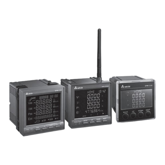
Ch ap te r 1 Prod uc t In tr od uc ti on Overview DPM-C520 DPM-C520W DPM-C320 1 - 3... -
Page 10: Safety Precautions
D PM -C52 0 /C5 20W /C32 0 Op era tio n M anu al Safety Precautions Installation Notes Install the power meter according to instructions on the manual. Use appropriate personal protective equipment (PPE) and follow safe electrical work practices. Only qualified electrical workers should install this equipment. - Page 11 Ch ap te r 1 Prod uc t In tr od uc ti on Maintenance and Inspection Notes While cleaning the equipment, be sure to unplug all external power sources first. Use a dry cloth to clean the equipment’s exterior. DO NOT open the equipment or touch the wiring inside to prevent personal injury as well as damage to electrical equipment or other property.
- Page 12 D PM -C52 0 /C5 20W /C32 0 Op era tio n M anu al MEMO 1 - 6...
- Page 13 Chapter 2 Specifications Table of Contents Electrical characteristics ..............2-2 Communications Specifications ............2-4 Operating the Display ................2-5 2.3.1 Menu Tree ..................2-6 Dimensions ..................2-8 2 - 1...
-
Page 14: Electrical Characteristics
D PM -C52 0 /C5 20W /C32 0 Op era tio n M anu al 2.1 Electrical characteristics Measurement Accuracy Voltage, current ± 0.5% Real power ± 0.5% Electric Electric quantities Real power, reactive ± 0.5% Reactive energy ± 0.5% power, apparent power power Total Harmonic... - Page 15 Baud rate 9600 / 19200 / 38400 bps 1. DPM-C520 / DPM-C520W: 96 * 96 * 95.4 mm Dimension (W x H x D) 2. DPM-C320: Mechanical 72 * 72 * 98 mm Characteristics 1. IP54 (front display), IP20 (meter body) 2.
-
Page 16: Communications Specifications
FCC Part 15 Class A, EN55011 Class A Harmonics Emissions IEC 61000-3-2 Flicker Emissions IEC 61000-3-3 2.2 Communications Specifications Communications DPM-C520 / DPM-C320 DPM-C520W RS-485 Modbus-RTU Modbus-RTU Baud rate 9600 / 19200 / 38400 bps 9600 / 19200 / 38400 bps... -
Page 17: Operating The Display
Ch ap te r 2 Spec i fica ti ons 2.3 Operating the Display DPM-C520 / DPM-C520W : Time UP key Title DOWN key Load percentage NEXT key Item Submenu Pulse light Unit Fault light Value BACK key Button Basic Mode Setting Mode Go to Menu or return to the Return to the previous screen without saving the... -
Page 18: Menu Tree
D PM - C 52 0 /C 5 20W /C32 0 Op era t io n M anu al DPM-C320: Homepage-parameter display: Parameters Content Display Line Voltage:1P3L、3P3L Phase Voltage:1P2L、3P4L Iavg Ptotal 2.3.1 Menu Tree DPM-C520 / DPM-C520W: SETUP TIM DAT COM SYS CT PT RST INFO VLN VLL ULN ULL ... - Page 19 Ch ap te r 2 Spec i fica ti ons DPM-C320: Ampere Power Alarm Reactive Power Baud Rate Reset Communication Apparent Power Current Transformer System Values Date Total Harmonic Distortion Default Value Time Displacement Power Factor Voltage Energy Phase Voltage...
-
Page 20: Dimensions
D PM -C52 0 /C5 20W /C32 0 Op era tio n M anu al Maximum Negative Active Energy Meter Model Positive Reactive Energy Minimum Negative Reactive Energy Active power Positive Apparent Power Power Factor Negative Apparent Power Active Power, Reactive 485 ON Disable Wi-Fi Function Power, Apparent Power... - Page 21 Ch ap te r 2 Spec i fica ti ons DPM-C520W (Front) DPM-C520 / C520W (Back) 2 - 9...
- Page 22 D PM -C52 0 /C5 20W /C32 0 Op era tio n M anu al DPM-C320 (Front) Unit: mm DPM-C320 (Back) Function VOLTAGE CURRENT Line voltage:35 to 690 VAC (L-L) Phase voltage:20 to 400 VAC (L-N) 2. Y connection (3P4W):...
- Page 23 Ch ap te r 2 Spec i fica ti ons Function VOLTAGE CURRENT L1/+ 100 ~ 240 Vac Control power 400 mA MAX L2/- Function VOLTAGE CURRENT Rated current 1A ~ 5A RS-485 -7 ~ +12 VDC Wiring Descriptions 250 mA fuse: Either positive or negative charge can be used on L1/+ and L2/-.
- Page 24 D PM -C52 0 /C5 20W /C32 0 Op era tio n M anu al MEMO 2 - 1 2...
-
Page 25: Chapter 3 Installation
Chapter 3 Installation Table of Contents Installation ..................3-2 3.1.1 Installation Environment ..............3-2 3.1.2 Installation Notes ................3-2 Basic Checks ..................3-5 Wiring ....................3-5 3.3.1 Wiring Diagrams ................3-5 3.3.2 Communication Characteristics ............3-8 3 - 1... -
Page 26: Installation Environment
Store the power meter in a clean, dry, and controlled environment. DPM-C520 / DPM-C520W store in an ambient temperature range of -30–80°C (-22–176°F). DPM-C320 store in an ambient temperature range of -30–60°C (-22–140°F). Store in a relative humidity range of 5–95%, non-condensing. ... - Page 27 C h a p t e r 3 I n s t a l l a t i o n Installation Steps Step 1: Before installing the power meter, open the square hole on the metal plate. Step 2: Push the meter into the hole and then slide the securing bracket in to the metal plate. Step 3: Allow 50 mm (2 inches) of clearance at the back of the meter for heat dissipation.
- Page 28 5 20 /C5 20W /C32 0 Op era tio n M anu al D P M - C Mounting Hole Dimensions 1. DPM-C520 / DPM-C520W: Unit: mm 2. DPM-C320: Unit: mm 3 - 4...
-
Page 29: Basic Checks
C h a p t e r 3 I n s t a l l a t i o n 3.2 Basic Checks Items Contents Regularly check for mounting looseness where the power meter and device are connected. Prevent foreign objects, such as oil, water, or metal powder entering the device through General Check the ventilation holes. - Page 30 Current Measurement AWG 10–22 8.0 kgf-cm (0.8 N·m) > 70°C RS-485 AWG 14–24 2.0 kgf-cm (0.2 N·m) > 70°C 2. DPM-C320: Connecting Terminals Wire Diameters Screw Turning Torque Wire heat resistance Operating Power AWG 10–22 5.0 kgf-cm (0.5 N·m) > 70°C Voltage Measurement AWG 10–22...
- Page 31 C h a p t e r 3 I n s t a l l a t i o n Connection Diagrams 3PH3W, Δ connection, 3 CT, No PT 3PH3W, Δ connection, 2 CT, No PT 3PH3W, Δ connection, 3 CT, 2 PT 3PH4W, Y connection, 3 CT, No PT 3PH4W, Y connection, 3 CT, 3 PT 3PH4W, Y connection, 2 CT, 3 PT...
-
Page 32: Communication Characteristics
5 20 /C5 20W /C32 0 Op era tio n M anu al D P M - C The following table lists the symbols used in the diagram. Symbol Terminal Description Grounding Current transformer Voltage transformer Fuse block Rated value: Y (3p4w):400/690 Vac ∆... - Page 33 C h a p t e r 3 I n s t a l l a t i o n Use shielded twisted-pair cables for RS485 communication. When connecting multiple devices in series, use the wiring method in the following diagram. Termina l Resistor Connect the D+ communication terminal for all devices on the same twisted pair cable.
- Page 34 5 20 /C5 20W /C32 0 Op era tio n M anu al D P M - C MEMO 3 - 1 0...
-
Page 35: Chapter 4 Operation
4.2.10 Wi-Fi Setup (485 ON/OFF) only available for DPM-C520W ....4-8 4.2.11 Alarm Setup ................. 4-9 4.2.12 Parameter Grouping Setup ............. 4-9 DPM-C320 Setups ................4-11 4.3.1 Communication Setup (COM) ............4-11 4.3.2 System Setup (SYS) ..............4-11 4.3.3 Current Transformer Setup (CT) ............4-11 4.3.4 Potential Transformer Setup (PT)............. - Page 36 5 20 /C5 20W /C32 0 Op era tio n M anu al P M - C Power Analysis Values ..............4-27 4.5.1 Total Harmonic Distortion Measurement ........... 4-27 4 - 2...
-
Page 37: General Operation
(PT), total positive active energy (ET). (DPM-C520 / DPM-C520W) Voltage values measured by the power meter, including total voltage (V), total current (I), total power (P). (DPM-C320) Phase voltage (VLN): phase voltage values measured by the power meter, including phase A voltage ... -
Page 38: Dpm-C520 / Dpm-C520W Setups
5 20 /C5 20W /C32 0 Op era tio n M anu al P M - C Reversed apparent energy page (-VAH): reversed apparent energy measured by the power meter, including reserved apparent energy (SH). Total harmonic distortion of current page (THD I): current harmonic distortion measured by the power ... -
Page 39: Date Setup (Dat)
C h a p t e r 4 O p e r a t i o n 4.2.3 Date Setup (DAT) Date: Present power meter date; the date format includes the last two digits of the year, month, date and ... -
Page 40: System Setup (Sys)
5 20 /C5 20W /C32 0 Op era tio n M anu al P M - C Press NEXT key to confirm the setting and start to set the next setting, parity. 10. When the option starts blinking, you can use UP and DOWN keys to select the parity you need. 11. -
Page 41: Potential Transformer Setup (Pt)
C h a p t e r 4 O p e r a t i o n Press UP key to enter the current transformer (CT) setting page. Use UP and DOWN keys to select the number for the primary-side current transformer. Press NEXT key to confirm the setting and start to set the next number for the primary-side current transformer. -
Page 42: Reset Setup (Rst)
5 20 /C5 20W /C32 0 Op era tio n M anu al P M - C 4.2.8 Reset Setup (RST) Default (DEF): Restore all the settings back to the defaults (including wireless settings). Energy (ENG): Reset all the accumulated energy values and automatic energy values. ... -
Page 43: Alarm Setup
C h a p t e r 4 O p e r a t i o n 4.2.11 Alarm Setup Alarm: Options are Enable and Disable (default). Pickup: When the meter exceeds the Pickup value (default: 0), it triggers the alarm. ... - Page 44 5 20 /C5 20W /C32 0 Op era tio n M anu al P M - C If you need the measured parameters of average phase current (Modbus addresses 0x126~0x127), you can use the function code 0x06 (single writing) or 0x10 (multiple writings) to write the Modbus address 0x126 in 0x50E and the Modbus address 0x127 in 0x50F.
-
Page 45: Dpm-C320 Setups
C h a p t e r 4 O p e r a t i o n 4.3 DPM-C320 Setups 4.3.1 Communication Setup (COM) Address (ID): device ID; its address setting range is 1-254 (default: 1). Baud Rate (BR): transmission speed; the setting options are 9600 kbps (default), 19200 and 38400 bps. -
Page 46: Potential Transformer Setup (Pt)
5 20 /C5 20W /C32 0 Op era tio n M anu al P M - C Steps: Press BACK key then input password to see the setting page. Use UP and DOWN keys to enter the system (CT) setting page. Use UP and DOWN keys to select the number for the primary-side current transformer. -
Page 47: Meter Information (Inf)
C h a p t e r 4 O p e r a t i o n 4.3.6 Meter Information (INF) Model Name (MD): C320 Firmware Version (FW): 1.XXXX Date (DT): Firmware release date MM.DD Steps: Press BACK key then input password to see the setting page. -
Page 48: Language
5 20 /C5 20W /C32 0 Op era tio n M anu al P M - C See the table below for a quick understanding on the setting. Use Function Codes to WRITE Parameters in Modbus address and store values in Modbus add. Function Codes WRITE Parameters in Modbus address Values stored in... -
Page 49: Wi-Fi Setup (Only Available For Dpm-C520W)
C h a p t e r 4 O p e r a t i o n 4.4 Wi-Fi Setup (only available for DPM-C520W) 4.4.1 Wi-Fi Specification Max. Communication 300 m Standards IEEE 802.11 b/g/n Distance Function code 03, 06, 10 Data Length 8-bits Communication... - Page 50 5 20 /C5 20W /C32 0 Op era tio n M anu al P M - C Password of AP password (for WPA2) = "1234567890" IP address of AP: 192.168.1.XXX (Be sure the IP address stays in the same network, 192.168.1.XXX; after reset, some AP changes its IP address section to 192.168.0.XXX.) In this example, we use 192.168.1.11 as the IP address of the router.
- Page 51 C h a p t e r 4 O p e r a t i o n After the settings are complete, you can see the AP connection is established. Use DPM-C520W to check the connection. Default IP address: 192.168.1.1; Slave ID: 1. Open the Command Prompt to ping IP: 192.168.1.1 and from the transmission you can determine ...
- Page 52 5 20 /C5 20W /C32 0 Op era tio n M anu al P M - C Open the Command Prompt to ping IP: 192.168.1.11 (router) and from the transmission you can determine the connection is successful. Use DPMSoft to set up the meter IP address and ID that is connected to the router. ...
- Page 53 If the router you are using is with AMPDU function, you need to disable this function. Otherwise, you can only use IEEE 802.11 b/g but not 802.11 b/g/n. The example below uses Delta router DVW-W02W2-E2 to demonstrate how to disable AMPDU. 4 - 1 9...
-
Page 54: Advanced Wi-Fi Setup
5 20 /C5 20W /C32 0 Op era tio n M anu al P M - C 4.4.3 Advanced Wi-Fi Setup Use DPMSoft to set up the router that DPM-C520W is going to connect, for example router’s SSID and password. And after that you can use the specific information to search for the router that DPM-C520W can connect to. - Page 55 C h a p t e r 4 O p e r a t i o n For V1.0008 (V1.0008 included) or later: Once you enter the station number, the station does NOT reflect on the IP address. For example, if you enter 1 in the field of the station, the IP address is 192.158.1.5. 4 - 2 1...
- Page 56 5 20 /C5 20W /C32 0 Op era tio n M anu al P M - C Steps: Use DPMSoft to set up RS485 COM Port and connect to DPM-C520W. Once DPM-C520W is connected, you can find the meter information after clicking “System Setting” button.
- Page 57 C h a p t e r 4 O p e r a t i o n Set up the Network on the same setting page. Set the router and the meter; see the example below. SSID: Delta_DPM_C520W Password: Delta_20181122Ww (optional) IP address of the Meter: 168.234.123.254 You can click the “Network Set”...
- Page 58 5 20 /C5 20W /C32 0 Op era tio n M anu al P M - C Use Wi-Fi to connect to the router “Delta_DPM-C520W”. Use your PC and open the Command Prompt to ping meter IP: 168.234.123.254. From the transmission you can determine if the connection is successful.
- Page 59 C h a p t e r 4 O p e r a t i o n Open DPMSoft again and use IP address to connect to the meter. Once DPM-C520W is connected, you can find the meter information after clicking “System Setting” button.
- Page 60 5 20 /C5 20W /C32 0 Op era tio n M anu al P M - C If there is any modification on the settings of SSID, Password and IP address, you need to click the “Reset Wi-Fi module” button or to turn off and then turn on the power meter to have the modifications reflected on the power meter.
-
Page 61: Power Analysis Values
C h a p t e r 4 O p e r a t i o n 4.5 Power Analysis Values 4.5.1 Total Harmonic Distortion Measurement The total harmonic distortion (THD) is a measurement of the harmonic distortion and is defined as the ratio between the power of the harmonic frequencies above the base frequency and the power of the base frequency. - Page 62 5 20 /C5 20W /C32 0 Op era tio n M anu al P M - C MEMO 4 - 2 8...
- Page 63 Chapter 5 Parameters and Functions Table of Contents Overview of Parameters ..............5-2 5 - 1...
-
Page 64: Overview Of Parameters
Second: 00–59 word Second 40006 Meter Constant 3200 uint P/kWh 0: None 2: DMP–C520 40007 Meter Model word 5: DMP–C520W 11:DPM-C320 40008 Day: 0–65535 uint Total running time of Hour: 00–23 Hour, the meter 40009 byte Minute Minute: 00–59 40010 Firmware version 0.0000 –... - Page 65 Ch ap te r 5 Para me ters a nd Func tio ns 0: 1A 40016 Secondary CT (A) word 1: 5A 40017 Primary PT 1 – 9999 uint 40018 Secondary PT 1 – 9999 uint 0: 3CT3PT 1: 3CT2PT 2: 3CT0PT 3: 2CT3PT Transformer...
- Page 66 D PM -C52 0 /C5 20W /C32 0 Op era tio n M anu al 4: Reset max./min. values 5: Reset SSID, PWD, IP to factory default (available for DPM-C520W) 6: Reset wireless module (available for DPM-C520W) Alarm – Over Current 0: Disable 40032 Alarm enable...
- Page 67 Ch ap te r 5 Para me ters a nd Func tio ns Pickup setpoint (line 40061 voltage value below 0.000 – 99999.999 float this value triggers 40062 alarm) 40063 Reserved Dropout setpoint (line 40064 voltage value 0.000 – 99999.999 float exceeding this value 40065...
- Page 68 D PM -C52 0 /C5 20W /C32 0 Op era tio n M anu al exceeding this value 40079 clears alarm) Alarm – Over Active Power 0: Disable 40095 Alarm enable word 1: Enable Pickup setpoint (total 40096 active power value 0.000 –...
- Page 69 Ch ap te r 5 Para me ters a nd Func tio ns exceeding this value 40111 triggers alarm) 40112 Reserved Dropout setpoint (total 40113 apparent power value 0.000 – 99999.999 float below this value 40114 clears alarm) 40115 Reserved Alarm –...
- Page 70 D PM -C52 0 /C5 20W /C32 0 Op era tio n M anu al 1. Meter Parameters: 0100 – 01FF 40257 Phase A voltage 0.000 – 99999.999 float 40258 40259 Phase B voltage 0.000 – 99999.999 float 40260 40261 Phase C voltage 0.000 –...
- Page 71 Ch ap te r 5 Para me ters a nd Func tio ns 40287 Line voltage 0.00 – 99.99 float unbalance 40288 40289 Phase A current 0.000 – 99999.999 float 40290 40291 Phase B current 0.000 – 99999.999 float 40292 40293 Phase C current 0.000 –...
- Page 72 D PM -C52 0 /C5 20W /C32 0 Op era tio n M anu al power factor of phase (positive: lag; negative: lead) 40318 40319 Total displacement -0.00000 – 1.00000 power factor of phase float (positive: lag; negative: lead) 40320 Total displacement 40321 -0.00000 –...
- Page 73 Ch ap te r 5 Para me ters a nd Func tio ns apparent power of 40344 phase A 40345 Instantaneous apparent power of 0.000 – 99999.999 float 40346 phase B 40347 Instantaneous apparent power of 0.000 – 99999.999 float 40348 phase C 40349...
- Page 74 D PM -C52 0 /C5 20W /C32 0 Op era tio n M anu al distortion for neutral 40380 line current 40381 Total harmonic distortion for phase A 0.000 – 999.999 float 40382 voltage Total harmonic 40383 distortion for phase B 0.000 –...
- Page 75 Ch ap te r 5 Para me ters a nd Func tio ns 40519 Maximum B–C line 0.000 – 99999.999 float voltage 40520 Year: 00–99 Year, 40521 byte Date of maximum Month Month: 1–12 B–C line voltage 40522 Date: 1–31 word Date Hour: 00–23...
- Page 76 D PM -C52 0 /C5 20W /C32 0 Op era tio n M anu al 40542 Second: 00–59 word Second 40543 Maximum phase C 0.000 – 99999.999 float voltage 40544 Year: 00–99 Year, 40545 byte Date of maximum Month Month: 1–12 phase C voltage 40546 Date: 1–31...
- Page 77 Ch ap te r 5 Para me ters a nd Func tio ns Hour: 00–23 Hour, 40565 byte Time of maximum Minute Minute: 00–59 phase C current 40566 Second: 00–59 word Second 40567 Maximum neutral line 0.000 – 99999.999 float current 40568 Year: 00–99...
- Page 78 D PM -C52 0 /C5 20W /C32 0 Op era tio n M anu al 40588 Date: 1–31 word Date Hour: 00–23 Hour, 40589 byte Time of maximum Minute Minute: 00–59 total active power 40590 Second: 00–59 word Second 40591 Maximum total 0.000 –...
- Page 79 Ch ap te r 5 Para me ters a nd Func tio ns Year: 00–99 Year, 40777 byte Date of minimum B–C Month Month: 1–12 line voltage 40778 Date: 1–31 word Date Hour: 00–23 Hour, 40779 byte Time of minimum B–C Minute Minute: 00–59 line voltage...
- Page 80 D PM -C52 0 /C5 20W /C32 0 Op era tio n M anu al voltage 40800 Year: 00–99 Year, 40801 byte Date of minimum Month Month: 1–12 phase C voltage 40802 Date: 1–31 word Date Hour: 00–23 Hour, 40803 byte Time of minimum Minute...
- Page 81 Ch ap te r 5 Para me ters a nd Func tio ns 40823 Minimum neutral line 0.000 – 99999.999 float current 40824 Year: 00–99 Year, 40825 byte Date of minimum Month Month: 1–12 neutral line current 40826 Date: 1–31 word Date Hour: 00–23...
- Page 82 D PM -C52 0 /C5 20W /C32 0 Op era tio n M anu al 40846 Second: 00–59 word Second 40847 Minimum total 0.000 – 99999.999 float kVAR reactive power 40848 Year: 00–99 Year, 40849 byte Date of minimum total Month Month: 1–12 reactive power...
- Page 83 Ch ap te r 5 Para me ters a nd Func tio ns Year: 00–99 Year, 41045 byte Alarm date of over Month Month: 1–12 line voltage 41046 Date: 1–31 word Date Hour: 00–23 Hour, 41047 byte Alarm time of over line Minute Minute: 00–59 voltage...
- Page 84 D PM -C52 0 /C5 20W /C32 0 Op era tio n M anu al 41064 Date: 1–31 word Date Hour: 00–23 Hour, 41065 byte Alarm time of under Minute Minute: 00–59 phase voltage 41066 Second: 00–59 word Second 0: Cleared Alarm status of over 41079 word...
- Page 85 Ch ap te r 5 Para me ters a nd Func tio ns Hour: 00–23 Hour, 41095 byte Alarm time of over Minute Minute: 00–59 apparent power 41096 Second: 00–59 word Second 0: Cleared Alarm status of over 41145 word frequency 1: Triggered Alarm times of over...
- Page 86 D PM -C52 0 /C5 20W /C32 0 Op era tio n M anu al Hour: 00–23 Hour, 41365 Reset energy time byte Minute Minute: 00–59 41366 Reset energy time Second: 00–59 word Second 6. Parameter Group: 0600 – 06FF Read data from group 41537 Read data from group...
- Page 87 Ch ap te r 5 Para me ters a nd Func tio ns F20C 101965 SSID_5 High/low: 0x21 – 0x7E byte F20D 101966 SSID_6 High/low: 0x21 – 0x7E byte F20E 101967 SSID_7 High/low: 0x21 – 0x7E byte F20F 101968 SSID_8 High/low: 0x21 –...
- Page 88 D PM -C52 0 /C5 20W /C32 0 Op era tio n M anu al MEMO 5 - 2 6...
-
Page 89: Chapter 6 Error Codes
Chapter 6 Error Codes Table of Contents Error Codes ..................6-2 Alarm Types ..................6-2 6 - 1... -
Page 90: Error Codes
5 20 /C5 20W /C32 0 Op era tio n M anu al D P M - C 6.1 Error Codes When an error occurs during operation, the power monitor sends an error code through Modbus. The following table lists the error codes and causes. Error Code Name Description... -
Page 91: Appendix A Accessories
12 A Appendix A Accessories Table of Contents DCT1000 Series ................... A-2 DCT2000 Series ................... A-4 Α − 1... -
Page 92: Dct1000 Series
D PM -C52 0 /C5 20W /C32 0 Op era tio n M anu al When measured current is higher than the rated specification for the device, use of an external current transformer (CT) is necessary. A.1 DCT1000 Series Electromagnetic Compatibility: CE-marking, IEC61869-2. Size of Rated External... - Page 93 Ap pen di x A Acc essor ies Model Dimension (mm) Number External Dimension: DCT-S301C 90 x 40 x 111 Size of Opening: 21 x 32 DCT-S211C DCT-S221C DCT-S231C External Dimension: 116.5 DCT-S241C x 52 x 147 Size of Opening: 50 x 80 DCT-S251C DCT-S261C DCT-S271C...
-
Page 94: Dct2000 Series
D PM -C52 0 /C5 20W /C32 0 Op era tio n M anu al Model Dimension (mm) Number External Dimension: 186.5 DCT-S291C x 52 x 252 Size of Opening: 81 x 160.5 DCT-S2A1C DCT-S2B1C A.2 DCT2000 Series Electromagnetic Compatibility: UL, UL2808. Measurem External Model... - Page 95 Ap pen di x A Acc essor ies Model Number Dimension (mm) External Dimension: DCT-S201B 90 x 40 x 110 Size of Opening: 20 x 30 DCT-S211B DCT-S221B External Dimension: DCT-S231B 115 x 57 x 158 DCT-S241B Size of Opening: 50 x 80 DCT-S251B DCT-S261B...
- Page 96 D PM -C52 0 /C5 20W /C32 0 Op era tio n M anu al MEMO Α − 6...
Need help?
Do you have a question about the DPM-C320 and is the answer not in the manual?
Questions and answers