Sign In
Upload
Manuals
Brands
INVT Manuals
DC Drives
CHV100-018G-4
User Manuals: INVT CHV100-018G-4 Control Inverter
Manuals and User Guides for INVT CHV100-018G-4 Control Inverter. We have
2
INVT CHV100-018G-4 Control Inverter manuals available for free PDF download: Operation Manual
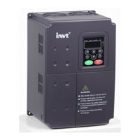
INVT CHV100-018G-4 Operation Manual (138 pages)
Close loop Vector Control Inverter
Brand:
INVT
| Category:
DC Drives
| Size: 2 MB
Table of Contents
Table of Contents
4
List of Figures
6
1 Introduction
9
Technology Features
9
Description of Name Plate
10
Figure 1.1 Nameplate of Inverter
10
Selection Guide
11
Parts Description
12
Figure 1.2 Parts of Inverter (15Kw and Below)
12
Figure 1.3 Parts of Inverters (18.5KW and Above)
13
Description of Extension Card
14
External Dimension
16
Figure1.4 Dimensions (15Kw and Below)
16
Figure 1.5 Dimensions (18.5~110Kw)
16
Figure 1.6 Dimensions (132~315Kw)
16
Figure 1.7 Dimensions (350Kw~630Kw)
17
2 Unpacking Inspection
18
3 Disassemble and Installation
19
Environmental Requirement
20
Figure 3.1 Relationship between Output Current and Altitude
20
Installation Space
21
Figure 3.2 Safety Space
21
Figure 3.3 Installation of Multiple Inverters
21
Dimensions of External Keypad
22
Disassembly
22
Figure 3.4 Dimension of Small Keypad
22
Figure 3.5 Dimension of Big Keypad
22
Figure 3.6 Disassembly of Plastic Cover
22
Figure 3.7 Disassembly of Metal Plate Cover
23
Figure 3.8 Open Inverter Cabinet
23
4 Wiring
24
Connections of Peripheral Devices
25
Figure 4.1 Connections of Peripheral Devices
25
Terminal Configuration
26
Main Circuit Terminals
26
Figure 4.2 Main Circuit Terminals (1.5~5.5Kw)
26
Figure 4.3 Main Circuit Terminals (7.5~15Kw)
26
Figure 4.4 Main Circuit Terminals (18.5~110Kw)
26
Figure 4.5 Main Circuit Terminals (132~315Kw)
26
Figure 4.6 Main Circuit Terminals (350~630Kw)
26
Control Circuit Terminals
27
Figure 4.7 Control Circuit Terminals
27
Typical Wiring Diagram
28
Figure4. 8 Wiring Diagram
28
Specifications of Breaker, Cable, Contactor and Reactor
29
Specifications of Breaker, Cable and Contactor
29
Specifications of AC Input/Output and DC Reactor
30
Specification of Braking Resistor
31
Wiring the Main Circuits
32
Wiring at the Side of Power Supply
32
Wiring for Inverter
33
Figure4.9 Wiring at Input Side
33
Wiring at Motor Side of Main Circuit
34
Wiring of Regenerative Unit
34
Figure 4.10 Wiring at Motor Side
34
Wiring of Common DC Bus
35
Figure 4.11 Wiring of Regenerative Unit
35
Ground Wiring (PE)
36
Wiring Control Circuit Terminals
36
Precautions
36
Figure 4.12 Wiring of Common DC Bus
36
Control Circuit Terminals
37
Jumper on Control Board
38
Installation Guidline to EMC Compliance
38
General Knowledge of EMC
38
EMC Features of Inverter
39
EMC Installation Guideline
39
5 Operation
42
Operating Keypad Description
42
Keypad Schematic Diagram
42
Button Function Description
42
Figure 5.1 Keypad Schematic Diagram
42
Indicator Light Description
43
Operation Process
44
Parameter Setting
44
Figure 5.2 Flow Chart of Parameter Setting
44
Shortcut Menu Setting
45
Shortcut Menu Operation
45
Figure 5.3 Shortcut Menu Operation
45
Fault Reset
46
Motor Parameter Autotune
46
Password Setting
46
Running State
47
Power-On Initialization
47
Stand-By
47
Operation
47
Fault
47
Quick Start
48
Figure 5.4 Quick Start Diagram
48
6 Detailed Function Description
49
P0 Group--Basic Function
49
Figure 6.1 Reference Frequency Diagram
53
Figure 6.2 Acceleration and Deceleration Time
54
Figure 6.3 Effect of Carrier Frequency
55
P1 Group--Start and Stop Control
58
Figure 6.4 Starting Diagram
58
Figure 6.5 S Curve Diagram
60
Figure 6.6 DC Braking Diagram
61
Figure 6.7 FWD/REV Dead Time Diagram
61
P2 Group--Motor Parameters
62
P3 Group--Vector Control
64
Figure 6.8 ASR Diagram
64
Figure 6.9 PI Parameter Diagram
64
P4 Group --V/F Control
67
Figure 6.10 Multiple V/F Curve Diagram
67
Figure 6.11 Torque Boost Diagram
68
Figure 6.12 V/F Curve Setting Diagram
69
P5 Group--Input Terminals
70
Figure 6.13 2-Wire Control Mode 1
75
Figure 6.14 2-Wire Control Mode 2
75
Figure 6.15 3-Wire Control Mode 1
75
Figure 6.16 3-Wire Control Mode 2
76
Figure 6.17 Relationship between AI and Corresponding Setting
77
P6 Group -- Output Terminals
79
Figure 6.18 Relationship between AO and Corresponding Setting
82
Figure 6.19 Relationship between HDO and Corresponding Setting
82
P7 Group --Display Interface
83
P8 Group --Enhanced Function
87
Figure 6.20 Skip Frequency Diagram
88
Figure 6.21 Traverse Operation Diagram
89
Figure 6.22 Timing Chart for Preset and Specified Count Reached
91
Figure 6.23 FDT Level Diagram
92
Figure 6.24 Frequency Arriving Detection Diagram
92
Figure 6.25 Droop Control Diagram
93
Figure 6.26 Simple Water-Supply Function Logical Diagram
94
P9 Group --PID Control
95
Figure 6.27 PID Control Diagram
95
Figure 6.28 Reducing Overshooting Diagram
97
Figure 6.29 Rapidly Stabilizing Diagram
97
Figure 6.30 Reducing Long-Cycle Oscillation Diagram
98
Figure 6.31 Reducing Short-Cycle Oscillation Diagram
98
Figure 6.32 Relationship between Bias Limit and Output Frequency
99
PA Group --Simple PLC and Multi-Step Speed Control
100
Figure 6.33 Simple PLC Operation Diagram
100
Figure 6.34 Multi-Steps Speed Operation Diagram
102
PB Group -- Protection Parameters
105
Figure 6.35 Motor Overload Protection Curve
105
Figure 6.36 Overload Pre-Warning Schematic Diagram
106
Figure 6.37 Over-Voltage Stall Function
107
Figure 6.38 Over-Current Stall Function
108
PC Group --Serial Communication
109
PD Group --Supplementary Function
109
PE Group -Factory Setting
109
7 Trouble Shooting
110
Fault and Trouble Shooting
110
Common Faults and Solutions
113
8 Maintenance
114
Daily Maintenance
114
Periodic Maintenance
116
Replacement of Wearing Parts
116
9 List of Function Parameters
117
Advertisement
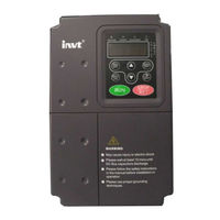
INVT CHV100-018G-4 Operation Manual (150 pages)
Close Loop Vector Control Inverter
Brand:
INVT
| Category:
Inverter
| Size: 3 MB
Table of Contents
Table of Contents
2
Safety Precautions
4
Technology Features
5
Introduction
5
Description of Name Plate
6
Selection Guide
7
Nameplate of Inverter
7
Parts Description
9
Product View
9
Description of Extension Card
10
External Dimensions
12
External Dimensions
13
Unpacking Inspection
14
Disassembly and Installation
15
Environmental Requirement
15
Installation Space
17
Dimensions of External Keypad
18
Disassembly
18
Wiring
20
Connections of Peripheral Devices
21
Terminal Configuration
22
Typical Wiring Diagram
23
Specifications of Breaker, Cable, Contactor and Reactor
24
Specifications of AC Input/Output and DC Reactor
25
Specification of Braking Unit and Braking Resistor
26
Specification of Input Filter and Output Filter
28
Wiring the Main Circuits
29
Wiring at the Side of Power Supply
29
Wiring for Inverter
29
Wiring at Motor Side of Main Circuit
30
Wiring of Regenerative Unit
30
Wiring of Common DC Bus
31
Wiring Control Circuit Terminals
32
Installation Guidline to EMC Compliance
34
EMC Features of Inverter
35
Noise Control
35
Site Wiring
36
Ground
36
Leakage Current
36
EMC Filter
37
Keypad Schematic Diagram
38
Button Function Description
38
Operating Keypad Description
38
Indicator Light Description
39
Parameter Setting
40
Operation Process
40
Shortcut Menu Setting
41
Shortcut Menu Operation
41
Fault Reset
42
Motor Parameter Autotune
42
Running State
43
Password Setting
43
Power-On Initialization
43
Stand-By
43
Operation
44
Fault
44
Quick Start
45
Detailed Function Description
46
P0 Group--Basic Function
46
Vector Control with PG
46
V/F Control
46
0: Keypad (LED Extinguished)
47
0: Valid, Save UP/DOWN Value When Power off
47
Simple PLC
48
Multi-Steps Speed
49
Communication
49
Reference Frequency Diagram
50
Effect of Carrier Frequency
53
Rotation Autotuning
54
P1 Group--Start and Stop Control
55
Static Autotuning
55
Deceleration to Stop
58
Coast to Stop
58
FWD/REV Dead Time Diagram
59
P2 Group--Motor Parameters
60
P3 Group--Vector Control
61
PI Parameter Diagram
62
P4 Group --V/F Control
65
P5 Group--Input Terminals
69
P6 Group -- Output Terminals
78
Oc/Relay Output Functions
79
AO/HDO Output Functions
80
P7 Group --Display Interface
82
P8 Group --Enhanced Function
88
Frequency Arriving Detection Diagram
93
Droop Control Diagram
93
Simple Water-Supply Function Logical Diagram
95
P9 Group --PID Control
96
Reducing Overshooting Diagram
98
Reducing Long-Cycle Oscillation Diagram
99
Reducing Short-Cycle Oscillation Diagram
99
PA Group --Simple PLC and Multi-Step Speed Control
100
Relationship between Bias Limit and Output Frequency
100
Simple PLC Operation Diagram
101
Multi-Steps Speed Operation Diagram
104
ACC/DEC Time Groups
105
PB Group -- Protection Parameters
106
Motor Overload Protection Curve
107
Overload Pre-Warning Schematic Diagram
108
Over-Voltage Stall Function
109
PD Group --Supplementary Function
110
PC Group --Serial Communication
110
PE Group -Factory Setting
111
Trouble Shooting
112
Fault and Trouble Shooting
112
Common Faults and Solutions
115
Power Supply Air Switch Trips off When Power on
116
Motor Doesn’t Move after Inverter Running
116
Daily Maintenance
117
Periodic Maintenance
118
Replacement of Wearing Parts
119
List of Function Parameters
120
Advertisement
Related Products
INVT CHV100-011G-4
INVT CHV100-015G-4
INVT CHV100-011G-2
INVT CHV100-015G-2
INVT CHV100-018G-2
INVT CHV100-022G-4
INVT CHV100-055G-4
INVT CHV100-075G-4
INVT CHV100-090G-4
INVT CHV100-004G-2
INVT Categories
Inverter
DC Drives
Servo Drives
Controller
I/O Systems
More INVT Manuals
Login
Sign In
OR
Sign in with Facebook
Sign in with Google
Upload manual
Upload from disk
Upload from URL