Table of Contents
Advertisement
Quick Links
Advertisement
Table of Contents

Related Manuals for INVT IPE300 Series


Summary of Contents for INVT IPE300 Series
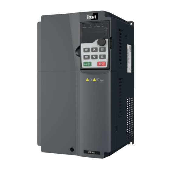
- Page 1 IPE300 Series Engineering VFD...
- Page 2 IPE300 series engineering VFD Change history Change description Version Release date First release. V1.0 June 2021...
- Page 4 Preface Thank you for choosing IPE300 series engineering variable-frequency drive (VFD). IPE300 series engineering VFD is a high-performance closed-loop vector single-drive system oriented to engineering applications. The VFD features high reliability, usability, maintainability, environment adaptability, and wide power range, provides enriched functions, and supports flexible configuration.
-
Page 5: Table Of Contents
IPE300 series engineering VFD Contents Contents Preface ............................i Contents ............................ii 1 Safety precautions ........................1 1.1 What this chapter contains ....................1 1.2 Safety definition ........................1 1.3 Warning ..........................1 1.4 Safety guidelines ......................... 2 1.4.1 Delivery and installation ..................... 2 1.4.2 Commissioning and running .................. - Page 6 IPE300 series engineering VFD Contents 4.3.1 Wiring diagram of the main circuit ................22 4.3.2 Terminal diagram of the main circuit ................ 23 4.3.3 Wiring procedure of main circuit terminals ............... 27 4.4 Standard wiring of the control circuit .................. 28 4.4.1 Wiring of basic control circuit ...................
- Page 7 IPE300 series engineering VFD Contents 5.5.16 Fault handling ....................... 99 5.5.17 Profibus-DP free programming function ............... 103 5.5.18 Water supply function ..................108 5.5.19 Brake control function ..................109 6 Function parameter list ......................110 6.1 What this chapter contains ....................110 6.2 Function parameter list ....................
- Page 8 IPE300 series engineering VFD Contents 7 Troubleshooting ........................246 7.1 What this chapter contains ....................246 7.2 Indications of alarms and faults ..................246 7.3 Fault reset ........................246 7.4 Fault history ........................246 7.5 Faults and solutions ......................246 7.5.1 Faults and solutions ....................
- Page 9 IPE300 series engineering VFD Contents 9.4.3 Command code 08H, diagnosis ................281 9.4.4 Command code 10H, continuous writing ..............281 9.4.5 Data address definition ..................282 9.4.6 Fieldbus scale ....................... 286 9.4.7 Error messages ..................... 287 9.4.8 Reading and writing examples ................289 9.5 Common communication faults ..................
- Page 10 IPE300 series engineering VFD Contents B.6.2 VFD category of C3 ....................337 Appendix C Dimension drawings ....................338 C.1 What this chapter contains ....................338 C.2 Keypad structure ......................338 C.2.1 LED keypad structure ................... 338 C.2.2 Optional LCD keypad structure ................338 C.2.3 Keypad mounting bracket ..................
- Page 11 IPE300 series engineering VFD Contents F.1 Product and service queries .................... 371 F.2 Feedback on INVT VFD manuals ..................371 F.3 Documents on the Internet ....................371 viii...
-
Page 12: Safety Precautions
IPE300 series engineering VFD Safety precautions 1 Safety precautions 1.1 What this chapter contains Read this manual carefully and follow all safety precautions before moving, installing, operating and servicing the product. Otherwise, equipment damage or physical injury or death may be caused. -
Page 13: Safety Guidelines
IPE300 series engineering VFD Safety precautions Symbol Name Description Abbreviation Read the operation manual before Read manual operating the equipment. Note Note Note Actions taken to ensure proper running. 1.4 Safety guidelines Only trained and qualified professionals are allowed to carry out related operations. -
Page 14: Commissioning And Running
IPE300 series engineering VFD Safety precautions Note: Select appropriate tools for VFD delivery and installation to ensure the safe and proper running and avoid physical injury or death. To ensure personal safety, take mechanical protective measures like wearing safety shoes and working uniforms. -
Page 15: Maintenance And Component Replacement
IPE300 series engineering VFD Safety precautions designated on the VFD, and ensure the voltage between + and - is lower than 36V. d) During operation, it is a must to ensure the permanent-magnet SM cannot run again by the action of external load; it is recommended to install an effective external braking device or cut off the direct electrical connection between the permanent-magnet SM and the VFD. -
Page 16: Quick Startup
Whether the VFD nameplate is consistent with the model identifier on the exterior surface of the packing box. If any problems are found, contact the local INVT dealer or office. Whether the accessories (including the manual, keypad, and extension card) inside the packing box are complete.If any problems are found, contact the local INVT dealer or office. -
Page 17: Checking After Installation
IPE300 series engineering VFD Quick startup Whether the actual ambient temperature is lower than -10° C. If the temperature is lower than -10° C, use heating devices. Note: When the VFD is built in a cabinet, the ambient temperature is the temperature of air in the cabinet. -
Page 18: Basic Commissioning
IPE300 series engineering VFD Quick startup 2.6 Basic commissioning Complete the basic commissioning as follows before the actual use of the VFD: According to the actual motor parameters, select the motor type, set motor parameters, and select the VFD control mode. -
Page 19: Product Overview
IPE300 series engineering VFD Product overview 3 Product overview 3.1 What this chapter contains This chapter mainly introduces the operation principles, product features, layouts, nameplates and model designation rules. 3.2 Basic principles The VFD is used to control asynchronous AC induction motor and permanent-magnet synchronous motor. - Page 20 IPE300 series engineering VFD Product overview (+) (-) Figure 3-3 380V (0045–0110) main circuit diagram (+) DC reactor (-) Figure 3-4 380V (0132 and higher) main circuit diagram (+) DC reactor (-) Figure 3-5 660V main circuit diagram Note: ...
-
Page 21: Product Specifications
IPE300 series engineering VFD Product overview The 0037 and lower VFD models carry built-in braking units, which are optional for the 0045–0110 (inclusive) models. The models with built-in braking units can also be connected to external braking resistors. Braking resistors are optional parts. - Page 22 IPE300 series engineering VFD Product overview Description Specifications Automatic voltage The output voltage can be kept constant although the grid regulation voltage changes. More than 30 protection functions, such as protection Fault protection against overcurrent, overvoltage, undervoltage, overtemperature, phase loss, and overload...
-
Page 23: Product Nameplate
Figure 3-7 Model description Field Sign Description Contents Product series Product series ① IPE300: IPE300 series engineering VFD abbreviation abbreviation 0004: 4kW (4kW G-type machine, with functions of ② Rated power Power range 5.5kW P-type machine) 4: AC 3PH 380V (-15%)–440V (+10%) Rated voltage: 380V ③... -
Page 24: Product Ratings
IPE300 series engineering VFD Product overview 3.6 Product ratings Table 3-1 AC 3PH 380V (-15%)–440V (+10%) Heavy-load application Light-load application Full load power Blowing Weight Output Input Output Output Input Output VFD model dissipa rate (kg) power current current power... - Page 25 IPE300 series engineering VFD Product overview The rated output current is the output current when the output voltage is 380V. Within the allowable input voltage range, the output current/power cannot exceed the rated output current/power. Table 3-2 AC 3PH 520V (-15%)–690V (+10%)
-
Page 26: Structure
IPE300 series engineering VFD Product overview 3.7 Structure The VFD structure is shown in the following figure (taking the 380V 0030 VFD model as an example). Figure 3-8 Structural diagram Item Description Upper cover Protects internal components and parts. For details, see section “Keypad instruction”. -
Page 27: Installation Guidance
INVT does not assume any liability whatsoever for any VFD installation which breaches local laws or regulations. If recommendations given by INVT are not followed, the VFD may experience problems that the warranty does not cover. 4.2 Mechanical installation 4.2.1 Installation environment... -
Page 28: Installation Direction
Lower than 1000 meters When the altitude exceeds 1000m, derate by 1% for every additional 100m. Altitude When the installation site altitude exceeds 3000m, consult the local INVT dealer or office. Vibration The max. amplitude of vibration cannot exceed 5.8m/s (0.6g) Installation Install the VFD vertically to ensure good heat dissipation performance. -
Page 29: Installation Method
IPE300 series engineering VFD Installation guidance A. Vertical installation B. Horizontal installation C. Transverse installation Figure 4-1 VFD installation direction 4.2.3 Installation method There are three kinds of installation modes based on different VFD dimensions. Wall-mounting: suitable for 380V 0315 and lower, and 660V 355kW and lower. -
Page 30: Single-Unit Installation
IPE300 series engineering VFD Installation guidance 4.2.4 Single-unit installation Hot air Cold air Figure 4-3 Single-unit installation Note: The minimum space of B and C is 100mm. 4.2.5 Multiple-unit installation Hot air Cold air Figure 4-4 Parallel installation Note: ... -
Page 31: Vertical Installation
IPE300 series engineering VFD Installation guidance 4.2.6 Vertical installation Windshield Cold Cold Windshield Figure 4-5 Vertical installation Note: During vertical installation, you must install windshield, otherwise, the VFD will experience mutual interference, and the heat dissipation effect will be degraded. -
Page 32: Tilted Installation
IPE300 series engineering VFD Installation guidance 4.2.7 Tilted installation Cold Cold Cold Figure 4-6 Tilted installation Note: During tilted installation, it is a must to ensure the air inlet duct and air outlet duct are separated from each other to avoid mutual interference. -
Page 33: Standard Wiring Of The Main Circuit
IPE300 series engineering VFD Installation guidance 4.3 Standard wiring of the main circuit 4.3.1 Wiring diagram of the main circuit Braking resistor (+) (-) Output reactor Input 3-phase power reactor 380V(-15%) ~ Output 0037 and lower 440V(+10%) filter Input 50/60Hz... -
Page 34: Terminal Diagram Of The Main Circuit
IPE300 series engineering VFD Installation guidance Braking unit DC reactor Braking resistor Output reactor Input reactor 22kW and higher Output 3-phase power filter 660V± 15% 50/60Hz Input filter Fuse Figure 4-8 Main circuit wiring diagram for AC 3PH 520V(-15%)–690V(+10%) Note: ... - Page 35 IPE300 series engineering VFD Installation guidance Figure 4-12 660V 22–45kW Figure 4-13 660V 55–132kW -24-...
- Page 36 IPE300 series engineering VFD Installation guidance Figure 4-14 380V 0132–0200 and 660V 160–220kW Figure 4-15 380V 0220–0315 and 660V 250–355kW -25-...
- Page 37 IPE300 series engineering VFD Installation guidance Figure 4-16 380V 0355–0500 and 660V 400–630kW Terminal name 380V 0132 and Terminal 380V 0037 and 380V Description higher lower 0045–0110 660V 3PH AC input terminals, connecting R, S, T Main circuit power input...
-
Page 38: Wiring Procedure Of Main Circuit Terminals
IPE300 series engineering VFD Installation guidance Terminal name 380V 0132 and Terminal 380V 0037 and 380V Description higher lower 0045–0110 660V Grounding terminal for safe protection; each machine must carry Grounding terminal for safe protection two PE terminals and proper... -
Page 39: Standard Wiring Of The Control Circuit
IPE300 series engineering VFD Installation guidance 4.4 Standard wiring of the control circuit 4.4.1 Wiring of basic control circuit IPE300 series VFD Forward running Analog output Reverse running 0-10V/0-20mA Fault reset Multi-step speed 1 output Multi-step speed 2 HDIA Multi-step speed 3... - Page 40 IPE300 series engineering VFD Installation guidance Terminal Description +10V Locally provided +10.5V power supply Input range: For AI1, 0–10V or 0–20mA; For AI2, -10V – +10V Input impedance: 20kΩ for voltage input or 250Ω for current input ...
-
Page 41: Input/Output Signal Connection Diagram
IPE300 series engineering VFD Installation guidance Terminal Description In addition to S1–S4 functions, the terminals can also act as high frequency pulse HDIA input channels. Max. input frequency: 50kHz Duty ratio: 30%– 70% HDIB Supporting quadrature encoder input; with the speed measurement function ... -
Page 42: Control Circuit Wiring Of The I/O Card 2
IPE300 series engineering VFD Installation guidance + 24V +24V + 24V + 24V + 24V External power(NPN mode) Internal power(NPN mode) Figure 4-20 NPN mode If input signal comes from PNP transistor, set the U-type short-contact tag based on the power used according to the following figure. -
Page 43: Wiring Protection
IPE300 series engineering VFD Installation guidance Terminal Description +24V User power supply provided by the VFD. Max. output current: 200mA +24V common terminal Internal impedance: 6.6kΩ Digital input 5 External power (-20%) – 48VDC(+10%), 24(-10%) – 48VAC(+10%) voltage input Digital input 6 ... -
Page 44: Protecting The Motor Against Thermal Overload
IPE300 series engineering VFD Installation guidance 4.5.3 Protecting the motor against thermal overload The motor must be protected against thermal overload. Once overload is detected, current must be cut off. The VFD is equipped with the motor thermal overload protection function, which can block output and cut off the current (if necessary) to protect the motor. -
Page 45: Basic Operation Guidelines
IPE300 series engineering VFD Basic operation guidelines 5 Basic operation guidelines 5.1 What this chapter contains This chapter describes the buttons, indicators, and display of the keypad, as well as the method of using the keyboard to view and modify the function code settings. - Page 46 IPE300 series engineering VFD Basic operation guidelines Name Description Off: The VFD is controlled through the keypad. Blinking: The VFD is controlled through terminals. On: The VFD is controlled through remote communication. Fault indicator LED on: in fault state TRIP...
-
Page 47: Keypad Display
IPE300 series engineering VFD Basic operation guidelines Name Description Press it to select display parameters Right-shifting rightward in the interface for the VFD in SHIFT stopped or running state or to select digits to change during parameter setting. Press it to run the VFD when using the Run key keypad for control. -
Page 48: Displaying Fault Information
IPE300 series engineering VFD Basic operation guidelines from left to right or press QUICK/JOG (P07.03=2) to shift selected parameters from right to left. 5.3.3 Displaying fault information After detecting a fault signal, the VFD enters the fault alarm state immediately, the fault code blinks on the keypad, and the TRIP indicator is on. -
Page 49: Setting A Password For The Vfd
IPE300 series engineering VFD Basic operation guidelines saved to the control board first, and then the level-2 menu is returned, displaying the next function code. If you press the PRG/ESC key, the level-2 menu is returned directly, without saving the set value of the parameter, and the current function code is displayed. -
Page 50: Viewing Vfd Status
IPE300 series engineering VFD Basic operation guidelines The units place The units place is blinking All digits are is blinking blinking DATA DATA DATA The units place The units place is blinking The units place is blinking is blinking Note: When setting the value, you can press to modify the value. - Page 51 IPE300 series engineering VFD Basic operation guidelines Start Power up after confirming the wiring is correct Restore to default value (P00.18=1) Set the motor parameters of Set the motor parameters of P02.01–P02.05 as per the P02.15–P02.19 as per the motor nameplate...
- Page 52 IPE300 series engineering VFD Basic operation guidelines The running command channel can be set by terminal commands besides P00.01 and P00.02. Multifunction terminal Multifunction terminal Multifunction terminal Channel of running function 36 function 37 function 38 commands Switch the running...
- Page 53 IPE300 series engineering VFD Basic operation guidelines Function Name Description Default code P02.08 are autotuned; when the present motor is motor 2, only P12.06, P12.07, and P12.08 autotuned. 0: No operation 1: Restore default values 2: Clear fault records 3: Lock keypad parameter 4.
-
Page 54: Vector Control
IPE300 series engineering VFD Basic operation guidelines Function Name Description Default code Function selection 36: Switch the running command channel to keypad of multifunction P05.01–P 37: Switch the running command channel to terminal digital input 05.06 38: Switch the running command channel to terminals (S1–S4,... - Page 55 IPE300 series engineering VFD Basic operation guidelines As the vector control algorithm is complicated, exercise caution before modifying vector control function parameters. R S T Rectifier bridge φ Calculate i exciting current Park IGBT conversion pulse bridge Calculate i torque current φ...
- Page 56 IPE300 series engineering VFD Basic operation guidelines Function Name Description Default code 0: Asynchronous motor (AM) P02.00 Type of motor 1 1: Synchronous motor (SM) Speed-loop P03.00 proportional gain 0–200.0 20.0 Speed-loop P03.01 0.000–10.000s 0.200s integral time 1 Low-point P03.02 frequency for 0.00Hz–P03.05...
- Page 57 IPE300 series engineering VFD Basic operation guidelines Function Name Description Default code 3: AI2 4: AI3 5: Pulse frequency HDIA 6: Multi-step torque 7: Modbus communication 8: PROFIBUS/CANopen/DeviceNet communication 9: Ethernet communication 10: Pulse frequency HDIB 11: EtherCAT/PROFINET communication 12: PLC Note: For setting sources 2–6 and 10, 100%...
- Page 58 IPE300 series engineering VFD Basic operation guidelines Function Name Description Default code frequency set through keypad in torque control Reverse rotation upper-limit P03.17 frequency set 50.00Hz through keypad in torque control 0: Keypad (P03.20) 1: AI1 2: AI2 3: AI3...
-
Page 59: Space Voltage Vector Control Mode
IPE300 series engineering VFD Basic operation guidelines Function Name Description Default code in constant power zone P03.24 Max. voltage limit 0.0–120.0% 100.0% P03.25 Pre-exciting time 0.000–10.000s 0.300s Enabling torque 0: Disable P03.32 control 1: Enable Ones place: Reserved 0: Reserved... - Page 60 IPE300 series engineering VFD Basic operation guidelines The VFD provides multiple kinds of V/F curve modes to meet different field needs. You can select corresponding V/F curve or set the V/F curve as needed. Suggestions: For the load featuring constant moment, such as conveyor belt which runs in straight line, as the whole running process requires constant moment, it is recommended to adopt the straight line V/F curve.
- Page 61 IPE300 series engineering VFD Basic operation guidelines 2) If torque boost is too large, the motor may encounter low-frequency vibration or overcurrent. If such a situation occurs, reduce the torque boost value. Output voltage V boost cut-off Output frequency f Energy-saving run During actual running, the VFD can search for the max.
- Page 62 IPE300 series engineering VFD Basic operation guidelines the frequency of the voltage and current. Customized V/F curve (V/F separation) function: When selecting the customized V/F curve function, you can specify the setting channels and -51-...
- Page 63 IPE300 series engineering VFD Basic operation guidelines acceleration/deceleration time of voltage and frequency respectively, which form a real-time V/F curve in combination manner. Note: This type of V/F curve separation can be applied in various variable-frequency power sources. However, exercise caution when setting parameters as improper settings may cause equipment damage.
- Page 64 IPE300 series engineering VFD Basic operation guidelines Function Name Description Default code 0.1%–10.0% Torque boost cut-off P04.02 0.0%–50.0% (of the rated frequency of motor 1) 20.0% of motor 1 V/F frequency point 1 P04.03 0.00Hz–P04.05 0.00Hz of motor 1 V/F voltage point 1 of P04.04...
- Page 65 IPE300 series engineering VFD Basic operation guidelines Function Name Description Default code of motor 2 V/F frequency point 1 P04.16 0.00Hz–P04.18 0.00Hz of motor 2 V/F voltage point 1 of P04.17 0.0%–110.0% 0.0% motor 2 V/F frequency point 2 P04.18 P04.16–P04.20...
- Page 66 IPE300 series engineering VFD Basic operation guidelines Function Name Description Default code communication 9: Ethernet communication 10: HDIB 11: EtherCat/Profinet communication 12: PLC 13: Reserved Voltage set through P04.28 0.0%–100.0% (of the motor rated voltage) 100.0% keypad P04.29 Voltage increase time 0.0–3600.0s 5.0s...
- Page 67 IPE300 series engineering VFD Basic operation guidelines Function Name Description Default code closed-loop function code is used to set the proportional proportional coefficient of reactive current closed-loop control. coefficient in SM V/F Setting range: 0–3000 control When the SM VF control mode is enabled, the...
-
Page 68: Torque Control
IPE300 series engineering VFD Basic operation guidelines Function Name Description Default code function code, the current closed-loop control in the IF control mode is enabled; and when the frequency is higher than that, the current closed-loop control in the IF control mode is disabled. - Page 69 IPE300 series engineering VFD Basic operation guidelines -58-...
- Page 70 IPE300 series engineering VFD Basic operation guidelines Function Name Description Default code 0: Sensorless vector control (SVC) mode 0 1: Sensorless vector control (SVC) mode 1 Speed control 2: Space voltage vector control mode P00.00 mode 3: Closed-loop vector control mode Note: If 0, 1 or 3 is selected, it is required to carry out motor parameter autotuning first.
- Page 71 IPE300 series engineering VFD Basic operation guidelines Function Name Description Default code 11: PLC 12: Reserved Note: For setting methods 1–11, 100% corresponds to the maximum frequency. Setting source of reverse rotation 0: Keypad (P03.17) P03.15 upper-limit 1–11: the same as P03.14...
-
Page 72: Motor Parameters
IPE300 series engineering VFD Basic operation guidelines Function Name Description Default code Braking torque P03.21 upper limit set 0.0–300.0% (of the motor rated current) 180.0% through keypad P17.09 Output torque -250.0–250.0% 0.0% Torque reference P17.15 -300.0–300.0% (of the motor rated current) 0.0%... - Page 73 IPE300 series engineering VFD Basic operation guidelines The control performance of the VFD is based on accurate motor models. Therefore, you need to carry out motor parameter autotuning before running a motor for the first time (taking motor 1 as an example).
- Page 74 IPE300 series engineering VFD Basic operation guidelines If static autotuning is selected for motor autotuning, there is no need to disconnect the motor from the load, but the control performance may be impacted as only a part of the motor parameters have been autotuned.
- Page 75 IPE300 series engineering VFD Basic operation guidelines Function Name Description Default code Model P02.06 Stator resistance of AM 1 0.001–65.535Ω depended Model P02.07 Rotor resistance of AM 1 0.001–65.535Ω depended Leakage inductance of Model P02.08 0.1–6553.5mH AM 1 depended Mutual inductance of AM Model P02.09...
- Page 76 IPE300 series engineering VFD Basic operation guidelines Function Name Description Default code PROFIBUS/CANopen/DeviceNet communication 3: Ethernet communication 4: EtherCAT/Profinet communication Tens place: indicates whether to enable switchover during running 0: Disable 1: Enable 0: Asynchronous motor (AM) P12.00 Type of motor 2...
-
Page 77: Start/Stop Control
IPE300 series engineering VFD Basic operation guidelines Function Name Description Default code Model P12.18 Rated voltage of SM 2 0–1200V depended Model P12.19 Rated current of SM 2 0.8–6000.0A depended Stator resistance of SM Model P12.20 0.001–65.535Ω depended Direct-axis inductance of Model P12.21... - Page 78 IPE300 series engineering VFD Basic operation guidelines -67-...
- Page 79 IPE300 series engineering VFD Basic operation guidelines Logic diagram for start after power-off restart is effective Standby Keypad The running state Stop Stop before power cut Restart after Communi power-cut cation Delay time of restart Waiting time of restart at >P01.23...
- Page 80 IPE300 series engineering VFD Basic operation guidelines Function Name Description Default code P01.02 Starting frequency hold time 0.0–50.0s 0.0s P01.03 Braking current before start 0.0–100.0% 0.0% P01.04 DC braking time before start 0.00–50.00s 0.00s 0: Linear 1: S curve P01.05 ACC/DEC mode Note: If mode 1 is selected, set P01.06,...
- Page 81 IPE300 series engineering VFD Basic operation guidelines Function Name Description Default code Wait time for restart after P01.22 0.0–3600.0s (valid when P01.21 is 1) 1.0s power-off P01.23 Start delay 0.0–60.0s 0.0s P01.24 Stop speed delay 0.0–100.0s 0.0s 0: Output without voltage...
-
Page 82: Frequency Setting
IPE300 series engineering VFD Basic operation guidelines Function Name Description Default code Model P08.04 ACC time 4 0.0–3600.0s depended Model P08.05 DEC time 4 0.0–3600.0s depended P08.06 Running frequency of jog 0.00Hz–P00.03(Max. output frequency) 5.00Hz Model P08.07 ACC time for jogging 0.0–3600.0s... - Page 83 IPE300 series engineering VFD Basic operation guidelines The VFD supports switch-over between different reference channels, and the rules for channel switch-over are shown as follows. Multifunction terminal Multifunction terminal Multifunction terminal Present reference function 13 function 14 function 15 channel...
- Page 84 IPE300 series engineering VFD Basic operation guidelines Multifunction terminal Multifunction terminal Multifunction terminal Present reference function 13 function 14 function 15 channel (Switch from channel A (Switch from combined (Switch from combined P00.09 to channel B) setting to channel A)
- Page 85 IPE300 series engineering VFD Basic operation guidelines Function Name Description Default code 8: Modbus communication 9: PROFIBUS/CANopen/DeviceNET communication 10: Ethernet communication 11: High-speed pulse HDIB 12: Pulse train AB 13: EtherCat/Profinet communication 14: PLC 15: Reserved Reference object of B 0: Max.
- Page 86 IPE300 series engineering VFD Basic operation guidelines Function Name Description Default code 0: Valid only when P00.06=0 or P00.07=0 1: Valid for all frequency setting methods 2: Invalid for multi-step speed running when multi-step speed running has the priority Hundreds place: Action selection for stop 0: Setting is valid.
-
Page 87: Analog Input
IPE300 series engineering VFD Basic operation guidelines Function Name Description Default code P17.02 Ramp reference frequency 0.00Hz–P00.03(Max. output frequency) 0.00Hz P17.14 Digital adjustment value 0.00Hz–P00.03 0.00Hz 5.5.9 Analog input The VFD carries two analog input terminals (AI1 is 0–10V/0–20mA (voltage input or current input can be set by P05.50);... - Page 88 IPE300 series engineering VFD Basic operation guidelines Function Name Description Default code Tens place: HDIB input type 0: HDIB is high-speed pulse input 1: HDIB is digital input P05.24 AI1 lower limit 0.00V–P05.26 0.00V Corresponding setting of AI1 0.0% P05.25 -300.0%–300.0%...
-
Page 89: Analog Output
IPE300 series engineering VFD Basic operation guidelines Function Name Description Default code 2: Input set through encoder, used together with HDIA 0.000 kHz – P05.45 HDIB lower limit frequency P05.47 0.000kHz Corresponding setting of 0.0% P05.46 -300.0%–300.0% HDIB lower limit frequency P05.47... - Page 90 IPE300 series engineering VFD Basic operation guidelines Setting Function Description Set frequency 0–Max. output frequency Ramp reference frequency 0–Max. output frequency 0–Synchronous speed corresponding to max. Rotational speed output frequency Output current (relative to the VFD) 0–Twice the VFD rated current Output current (relative to motor) 0–Twice the motor rated current...
- Page 91 IPE300 series engineering VFD Basic operation guidelines Setting Function Description C_AO1 from the PLC 1000 corresponds to 100.0%. C_AO2 from the PLC 1000 corresponds to 100.0%. 0–Twice the motor rated synchronous rotation Rotational speed speed 31–47 Reserved Related parameter list:...
- Page 92 IPE300 series engineering VFD Basic operation guidelines Function Name Description Default code communication Torque current (bipolar, 100% corresponding to 10V) 23: Exciting current (100% corresponding to 10V) 24: Set frequency (bipolar) 25: Ramp reference frequency (bipolar) 26: Rotational speed (bipolar)
-
Page 93: Digital Input
IPE300 series engineering VFD Basic operation guidelines 5.5.11 Digital input The VFD carries four programmable digital input terminals and two HDI input terminals. The function of all the digital input terminals can be programmed through function codes. HDI input terminal can be set to act as high-speed pulse input terminal or common digital input terminal;... - Page 94 IPE300 series engineering VFD Basic operation guidelines Setting Function Description The VFD decelerates to stop, however, all the run parameters are in memory state, such as PLC parameter, wobbling Pause running frequency, and PID parameter. After this signal disappears, the VFD will revert to the state before stop.
- Page 95 IPE300 series engineering VFD Basic operation guidelines Setting Function Description ACC/DEC time selection The status of the two terminals can be combined to select four groups of ACC/DEC time. Terminal 1 Terminal 2 ACC/DEC time Parameter ACC/DEC time 1 P00.11/P00.12...
- Page 96 IPE300 series engineering VFD Basic operation guidelines Setting Function Description Switch the running When the function is enabled, the running command channel command channel to is switched to terminal. When the function is disabled, the terminal running command channel is restored to the previous setting.
- Page 97 IPE300 series engineering VFD Basic operation guidelines Setting Function Description Motor overtemperature When there is motor overtemperature fault input, the motor fault input stops due to the fault. Switch from VC to space When the function is enabled in stopped state, space voltage voltage vector control vector control is used.
- Page 98 IPE300 series engineering VFD Basic operation guidelines Related parameter list: Function Name Description Default code 0x00–0x11 Ones place: HDIA input type 0: HDIA is high-speed pulse input P05.00 HDI input type 1: HDIA is digital input 0x00 Tens place: HDIB input type...
- Page 99 IPE300 series engineering VFD Basic operation guidelines Function Name Description Default code 26: Pause wobbling frequency 27: Reset wobbling frequency 28: Counter reset 29: Switch between speed control and torque control 30: Disable ACC/DEC 31: Trigger the counter 32: Reserved...
- Page 100 IPE300 series engineering VFD Basic operation guidelines Function Name Description Default code 57: Motor overtemperature fault input 59: Switch to V/F control 60: Switch to FVC control 61: Switch PID polarities 62: Reserved 63: Enable servo 64: Limit on forward running...
-
Page 101: Digital Output
IPE300 series engineering VFD Basic operation guidelines Function Name Description Default code P05.18 S4 switch-on delay 0.000–50.000s 0.000s P05.19 S4 switch-off delay 0.000–50.000s 0.000s P05.20 HDIA switch-on delay 0.000–50.000s 0.000s P05.21 HDIA switch-off delay 0.000–50.000s 0.000s P05.22 HDIB switch-on delay 0.000–50.000s... - Page 102 IPE300 series engineering VFD Basic operation guidelines Setting Function Description VFD in fault Output ON signal when VFD fault occurred Frequency level Refer to the description for P08.32 P08.33 detection FDT1 Frequency level Refer to the description for P08.34 P08.35...
- Page 103 IPE300 series engineering VFD Basic operation guidelines Setting Function Description When the pulse superposition terminal input function is valid, the Superposing pulses output is valid. STO action When an STO fault occurs, the output is valid. Positioning completed When positioning is completed, the output is valid.
- Page 104 IPE300 series engineering VFD Basic operation guidelines Function Name Description Default code 8: Frequency reached 9: Running in zero speed 10: Upper limit frequency reached 11: Lower limit frequency reached 12: Ready for running 13: Pre-exciting 14: Overload pre-alarm 15: Underload pre-alarm...
-
Page 105: Simple Plc
IPE300 series engineering VFD Basic operation guidelines Function Name Description Default code 44: C_RO1 from PLC (Set P27.00 to 1.) 45: C_RO2 from PLC (Set P27.00 to 1.) 46: C_RO3 from PLC (Set P27.00 to 1.) 47: C_RO4 from PLC (Set P27.00 to 1.) - Page 106 IPE300 series engineering VFD Basic operation guidelines P10.01 (simple PLC memory selection) P10.00(simple PLC mode) No memory after power off Set frequency Stop after running Power cut during once running Memory after Restart running power off after the first Setup of running...
-
Page 107: Multi-Step Speed Running
IPE300 series engineering VFD Basic operation guidelines Function Name Description Default code P10.13 Running time of step 5 0.0–6553.5s (min) 0.0s P10.14 Multi-step speed 6 -100.0–100.0% 0.0% P10.15 Running time of step 6 0.0–6553.5s (min) 0.0s P10.16 Multi-step speed 7 -100.0–100.0%... - Page 108 IPE300 series engineering VFD Basic operation guidelines P10.02 multi-step speed 0 BIT0 P10.34 P10.03 running time of 0 step BIT1 Terminal function 16 Acceleration/deceleration time Multi-step speed selection of 0–7 section of terminal 1 simple PLC Terminal function 17 P10.04 multi-step speed 1...
-
Page 109: Local Encoder Input
IPE300 series engineering VFD Basic operation guidelines Function Name Description Default code P10.10 Multi-step speed 4 -100.0–100.0% 0.0% P10.11 Running time of step 4 0.0–6553.5s (min) 0.0s P10.12 Multi-step speed 5 -100.0–100.0% 0.0% P10.13 Running time of step 5 0.0–6553.5s (min) 0.0s... -
Page 110: Fault Handling
IPE300 series engineering VFD Basic operation guidelines Function Name Description Default code 0x00–0x11 Ones place: HDIA input type 0: HDIA is high-speed pulse input P05.00 HDI input type 1: HDIA is digital input 0x00 Tens place: HDIB input type 0: HDIB is high-speed pulse input... - Page 111 IPE300 series engineering VFD Basic operation guidelines Related parameter list: Function Description Default Name code 0: No fault P07.27 Present fault type 1: Inverter unit U-phase protection (OUt1) P07.28 Last fault type 2: Inverter unit V-phase protection (OUt2) P07.29 2nd-last fault type 3: Inverter unit W-phase protection (OUt3) P07.30...
- Page 112 IPE300 series engineering VFD Basic operation guidelines Function Description Default Name code 33: To-ground short-circuit fault 2 (ETH2) 34: Speed deviation fault (dEu) 35: Mal-adjustment fault (STo) 36: Underload fault (LL) 37: Encoder disconnection fault (ENC1O) Encoder direction reversal fault...
- Page 113 IPE300 series engineering VFD Basic operation guidelines Function Description Default Name code (F3-Er) 63: Communication timeout of the card at slot 1 (C1-Er) 64: Communication timeout of the card at slot 2 (C2-Er) 65: Communication timeout of the card at...
-
Page 114: Profibus-Dp Free Programming Function
IPE300 series engineering VFD Basic operation guidelines Function Description Default Name code P07.45 Bus voltage at last fault 0.0V P07.46 0.0° C Max. temperature at last fault Input terminal status at last P07.47 fault Output terminal status at last P07.48... - Page 115 IPE300 series engineering VFD Basic operation guidelines Power-on initialization Fault signal OFF2 valid Prohibit ≥ Receive the bit value of & running status CW1 selection OFF2 Do not receive the bit value of CW1 selection OFF2 ≥ P90.16 CW1 function &...
- Page 116 IPE300 series engineering VFD Basic operation guidelines Function Name Description Default code P90.08 Bit 08 selection of CW 1 6: Fault reset (0: disable; 1: enable) 7: Jog forward (0: disable; 1: enable) P90.09 Bit 09 selection of CW 1 8: Jog reversely (0: disable;...
- Page 117 IPE300 series engineering VFD Basic operation guidelines Function Name Description Default code P15.02 Received PZD2 P91.00–P91.21 calibration value P15.03 Received PZD3 0: Disable 1: Set frequency (0–Fmax (Unit: 0.01Hz)) P15.04 Received PZD4 2: PID reference (0–1000, in which 1000 P15.05 Received PZD5 corresponds to 100.0%)
- Page 118 IPE300 series engineering VFD Basic operation guidelines Function Name Description Default code (signed) 17: Low-order bit of position feedback (unsigned) 18: Position feedback setting flag (position feedback can be set only after this flag is set to 1 and then to 0) 19–20: Reserved...
-
Page 119: Water Supply Function
IPE300 series engineering VFD Basic operation guidelines Take sent PZD2 as an example: PZD2 sent value = VFD internal value * P91.22/P91.23 Function Name Description Default code Numerator of sent PZD2 P91.22 16384 Numerator of sent PZD Sent conversion base value... -
Page 120: Brake Control Function
IPE300 series engineering VFD Basic operation guidelines 5.5.19 Brake control function P94 group provides the parameter setting of brake control. When the drive is not active, the brake is used to protect the drive from undesired movements, such as caused by potential energy loads or vertical running loads. -
Page 121: Function Parameter List
IPE300 series engineering VFD Function parameter list 6 Function parameter list 6.1 What this chapter contains This chapter lists all the function codes and corresponding description of each function code. 6.2 Function parameter list The function parameters of the VFD are divided into groups by function. Among the function parameter groups, the P98 group is the analog input and output calibration group, while the P99 group contains the factory function parameters, which are user inaccessible. -
Page 122: P00 Group--Basic Functions
IPE300 series engineering VFD Function parameter list parameters. Incorrect parameter setting may cause operation exceptions or even damage to the VFD.) If password protection is not in locked state, you can change the password any time. You can set P07.00 to 0 to cancel the user password. - Page 123 IPE300 series engineering VFD Function parameter list Function Name Description Default Modify code limit of the running frequency is used for running. Setting range: P00.05–P00.03 (Max. output frequency) The lower limit of the running frequency is the lower limit of the output frequency of the VFD,...
- Page 124 IPE300 series engineering VFD Function parameter list Function Name Description Default Modify code When A and B frequency commands select the keypad for setting, the value of the function Frequency set code is the original setting one of the frequency ○...
- Page 125 IPE300 series engineering VFD Function parameter list Function Name Description Default Modify code Advantage of high carrier frequency: ideal current waveform, little current harmonic wave and motor noise. Disadvantage high carrier frequency: increasing the switch loss, increasing VFD temperature and the impact to the output capacity.
-
Page 126: P01 Group--Start And Stop Control
IPE300 series engineering VFD Function parameter list Function Name Description Default Modify code 0: G type ◎ P00.17 VFD type 1: P type 0: No operation 1: Restore default values 2: Clear fault records 3: Lock keypad parameter 4. Reserved... - Page 127 IPE300 series engineering VFD Function parameter list Functio Name Description Default Modify n code frequency. If the set frequency is lower than the starting frequency, the VFD stops running and keeps in the standby state. The starting frequency is not limited in the lower limit frequency.
- Page 128 IPE300 series engineering VFD Function parameter list Functio Name Description Default Modify n code The curvature of S curve is determined by the Time of starting ACC range and ACC/DEC time. ◎ P01.06 segment of ACC S 0.1s Output frequency f curve t1=P01.06...
- Page 129 IPE300 series engineering VFD Function parameter list Functio Name Description Default Modify n code output frequency) P01.10 setting range: 0.00–30.00s P01.11 setting range: 0.0–100.0% P01.12 setting range: 0.0–50.0s This function code indicates the transition time specified in P01.14 during FWD/REV rotation switching.
- Page 130 IPE300 series engineering VFD Function parameter list Functio Name Description Default Modify n code Note: Exercise caution before using this function. Otherwise, serious result may follow. The function code determines the running state of the VFD when the set frequency is lower than Action selected the lower-limit one.
- Page 131 IPE300 series engineering VFD Function parameter list Functio Name Description Default Modify n code re-powered on. power-off Output frequency t1=P01.22 t2=P01.23 Running Running Power off Power on Setting range: 0.0–3600.0s (Valid only when P01.21=1) After a VFD running command is given, the VFD is in standby state and restarts with the delay ○...
-
Page 132: P02 Group--Parameters Of Motor 1
IPE300 series engineering VFD Function parameter list P02 group––Parameters of motor 1 Function Name Description Default Modify code 0: Asynchronous motor (AM) ◎ P02.00 Type of motor 1 1: Synchronous motor (SM) Rated power of Model ◎ P02.01 0.1–3000.0kW AM 1... - Page 133 IPE300 series engineering VFD Function parameter list Function Name Description Default Modify code Magnetic saturation ○ P02.14 0.0–100.0% 40.0% coefficient 4 of iron core of AM 1 Rated power of Model ◎ P02.15 0.1–3000.0kW SM 1 depended Rated frequency ◎...
- Page 134 IPE300 series engineering VFD Function parameter list Function Name Description Default Modify code (without low speed compensation). Because heat dissipation function variable-frequency motor is not impacted by the rotation speed, it is not necessary to adjust the protection value at low speed running.
-
Page 135: P03 Group--Vector Control Of Motor 1
IPE300 series engineering VFD Function parameter list Function Name Description Default Modify code P02.31–P ○ Reserved 0–65535 02.32 P03 group––Vector control of motor 1 Function Name Description Default Modify code Speed-loop The parameters P03.00–P03.05 are applicable ○ P03.00 proportional gain only to vector control mode. - Page 136 IPE300 series engineering VFD Function parameter list Function Name Description Default Modify code P03.02 setting range: 0.00Hz–P03.05 P03.03 setting range: 0.0–200.0 P03.04 setting range: 0.000–10.000s P03.05 setting range: P03.02–P00.03 (Max. output frequency) Speed-loop ○ P03.06 0–8 (corresponding to 0–2 /10ms)
- Page 137 IPE300 series engineering VFD Function parameter list Function Name Description Default Modify code Note: For setting sources 2–6 and 10, 100% corresponds to three times the rated motor current. Torque set ○ P03.12 -300.0%–300.0% (of the motor rated current) 20.0%...
- Page 138 IPE300 series engineering VFD Function parameter list Function Name Description Default Modify code 0: Keypad (P03.20) 1: AI1 2: AI2 3: AI3 4: Pulse frequency HDIA 5: Modbus communication PROFIBUS/CANopen/DeviceNet Setting source of communication ○ P03.18 electromotive 7: Ethernet communication...
- Page 139 IPE300 series engineering VFD Function parameter list Function Name Description Default Modify code curvature by modifying the flux-weakening control coefficient. The larger the coefficient, the steeper the curve, the smaller the coefficient, the smoother the curve. P03.22 setting range: 0.1–2.0 setting range: 10% –100.0%...
- Page 140 IPE300 series engineering VFD Function parameter list Function Name Description Default Modify code Ones place: Reserved 0: Reserved 1: Reserved Tens place: Reserved 0: Reserved 1: Reserved Control Hundreds place: indicates whether to enable ○ P03.35 optimization 0x0000 speed-loop integral separation...
-
Page 141: P04 Group--V/F Control
IPE300 series engineering VFD Function parameter list Function Name Description Default Modify code Due to friction force, it is required to set certain Inertia identification torque for the inertia identification to ○ identification P03.43 10.0% be performed properly. torque 0.0–100.0% (of the rated motor torque) - Page 142 IPE300 series engineering VFD Function parameter list Function Name Description Default Modify code In order to compensate for low-frequency torque characteristics, you can make some boost compensation for the output voltage. P04.01 relative to the max. output voltage V Torque boost of ○...
- Page 143 IPE300 series engineering VFD Function parameter list Function Name Description Default Modify code V/F frequency Output voltage ○ P04.07 0.00Hz 100.0% point 3 of motor 1 Output frequency(Hz) f2 f3 P04.03 setting range: 0.00Hz–P04.05 P04.04 setting range: 0.0%–110.0% (of the rated...
- Page 144 IPE300 series engineering VFD Function parameter list Function Name Description Default Modify code phenomenon. Oscillation Setting range of P04.10: 0–100 30.00H ○ P04.11 setting range: 0–100 P04.12 control threshold P04.12 setting range: 0.00Hz–P00.03 (Max. of motor 1 output frequency) This group of function code defines the V/F curve of motor 2 to meet the needs of different loads.
- Page 145 IPE300 series engineering VFD Function parameter list Function Name Description Default Modify code △f=f -n*p/60 Of which, f is the rated frequency of the motor 2, corresponding to function code P12.02. n is the rated rotating speed motor corresponding to function code P12.03. p is the number of pole pairs of the motor.
- Page 146 IPE300 series engineering VFD Function parameter list Function Name Description Default Modify code 10: HDIB 11: EtherCat/Profinet communication 12: PLC 13: Reserved The function code is the voltage digital setting Voltage set when "keypad" is selected as the voltage setting ○...
- Page 147 IPE300 series engineering VFD Function parameter list Function Name Description Default Modify code Setting range: -100.0%–+100.0% (of the motor rated current) When the SM V/F control mode is enabled, the Frequency function code is used to set the frequency threshold for 50.00H...
- Page 148 IPE300 series engineering VFD Function parameter list Function Name Description Default Modify code mode for AM 1 output current closed-loop control. Setting range: 0–5000 When IF control is adopted for AM 1, the function code is used to set the frequency threshold for switching off the output current closed-loop control.
-
Page 149: P05 Group--Input Terminals
IPE300 series engineering VFD Function parameter list Function Name Description Default Modify code End frequency point for motor 1 25.00H ○ P04.50 P04.44–P00.03 switching off IMVF mode End frequency point for motor 2 25.00H ○ P04.51 P04.49–P00.03 switching off IMVF mode P05 group––Input terminals... - Page 150 IPE300 series engineering VFD Function parameter list Function Name Description Default Modify code 16: Multi-step speed terminal 1 17: Multi-step speed terminal 2 18: Multi-step speed terminal 3 19: Multi-step speed terminal 4 20: Pause multi-step speed running 21: ACC/DEC time selection 1...
- Page 151 IPE300 series engineering VFD Function parameter list Function Name Description Default Modify code 47: Spindle zeroing position selection 2 48: Spindle scale division selection 1 49: Spindle scale division selection 2 50: Spindle scale division selection 3 51: Terminal for switching between position...
- Page 152 IPE300 series engineering VFD Function parameter list Function Name Description Default Modify code The function code is used to set the filter time for Digital input filter S1–S4, HDIA, and HDIB. In strong interference ○ P05.09 0.010s time cases, increase the value to avoid maloperation.
- Page 153 IPE300 series engineering VFD Function parameter list Function Name Description Default Modify code terminal needs to be closed, and terminal FWD generates a rising edge signal, then the VFD starts to run in the direction set by the state of terminal REV;...
- Page 154 IPE300 series engineering VFD Function parameter list Function Name Description Default Modify code Running direction FWD run OFF→ON FWD run REV run OFF→ON REV run Decelerate ON→OFF to stop Sin: Three-wire control; FWD: Forward running; REV: Reverse running Note: For two-wire controlled running mode,...
- Page 155 IPE300 series engineering VFD Function parameter list Function Name Description Default Modify code S3 switch-off Note: After a virtual terminal is enabled, the state ○ P05.17 0.000s delay of the terminal can be changed only in S4 switch-on communication mode.
- Page 156 IPE300 series engineering VFD Function parameter list Function Name Description Default Modify code Corresponding input. Increasing the value properly can enhance ○ P05.34 setting of AI2 analog input anti-interference but may reduce the 0.0% middle value 2 sensitivity of analog input.
-
Page 157: P06 Group--Output Terminals
IPE300 series engineering VFD Function parameter list Function Name Description Default Modify code HDIB high-speed 0: Input set through frequency pulse input 1: Reserved ◎ P05.44 function 2: Input set through encoder, used together with selection HDIA HDIB lower limit 0.000... - Page 158 IPE300 series engineering VFD Function parameter list Function Name Description Default Modify code output 5: VFD in fault 6: Frequency level detection FDT1 7: Frequency level detection FDT2 8: Frequency reached 9: Running in zero speed 10: Upper limit frequency reached...
- Page 159 IPE300 series engineering VFD Function parameter list Function Name Description Default Modify code 42: C_Y2 from PLC (Set P27.00 to 1.) 43: C_HDO from PLC (Set P27.00 to 1.) 44: C_RO1 from PLC (Set P27.00 to 1.) 45: C_RO2 from PLC (Set P27.00 to 1.) 46: C_RO3 from PLC (Set P27.00 to 1.)
- Page 160 IPE300 series engineering VFD Function parameter list Function Name Description Default Modify code ○ P06.14 AO1 output 0: Running frequency ○ 1: Set frequency P06.15 Reserved 2: Ramp reference frequency 3: Rotational speed (10V corresponds to the speed corresponding max.
- Page 161 IPE300 series engineering VFD Function parameter list Function Name Description Default Modify code 26: Rotational speed (bipolar) 27: Value 2 set through EtherCAT/Profinet communication 28: C_AO1 (Set P27.00 to 1) 29: C_AO2 (Set P27.00 to 1) 30: Rotational speed (10V corresponds to the...
-
Page 162: P07 Group--Human-Machine Interface
IPE300 series engineering VFD Function parameter list Function Name Description Default Modify code HDO output ○ P06.29 P06.27–100% 100.0% upper limit HDO output 50.00 ○ P06.30 corresponding to 0.00–50.00Hz upper limit HDO output filter ○ P06.31 0.000s–10.000s 0.000s time P06.32... - Page 163 IPE300 series engineering VFD Function parameter list Function Name Description Default Modify code Range: 0–4 0: No operation 1: Upload parameters to the keypad Download parameters (including motor ◎ P07.01 Parameter copy parameters) 3: Download non-motor parameters 4: Download motor parameters Range: 0x00–0x27...
- Page 164 IPE300 series engineering VFD Function parameter list Function Name Description Default Modify code Linear speed 0.1–999.9% ○ P07.10 display Linear speed=(Mechanical rotation speed) * 1.0% coefficient P07.10 Rectifier bridge ● P07.11 -20.0~120.0° C temperature Inverter ● P07.12 -20.0~120.0° C temperature Control board ●...
- Page 165 IPE300 series engineering VFD Function parameter list Function Name Description Default Modify code Present fault 0: No fault ● P07.27 type 1: Inverter unit U-phase protection (OUt1) ● 2: Inverter unit V-phase protection (OUt2) P07.28 Last fault type 3: Inverter unit W-phase protection (OUt3) 2nd-last fault ●...
- Page 166 IPE300 series engineering VFD Function parameter list Function Name Description Default Modify code 36: Underload fault (LL) 37: Encoder disconnection fault (ENC1O) 38: Encoder direction reversal fault (ENC1D) 39: Encoder Z-pulse disconnection fault (ENC1Z) 40: Safe torque off (STO) 41: Channel 1 safety circuit exception (STL1)
- Page 167 IPE300 series engineering VFD Function parameter list Function Name Description Default Modify code 70: PT100 overtemperature (OtE1) 71: PT1000 overtemperature (OtE2) 72: Brake feedback signal error (E-brF) 73–79: Reserved Running ● P07.33 frequency at 0.00Hz present fault Ramp reference ●...
-
Page 168: P08 Group--Enhanced Functions
IPE300 series engineering VFD Function parameter list Function Name Description Default Modify code Max. ● P07.46 temperature at 0.0° C last fault Input terminal ● P07.47 status at last fault Output terminal ● P07.48 status at last fault Running ●... - Page 169 IPE300 series engineering VFD Function parameter list Function Name Description Default Modify code inverter unit is the first group. The factory Model ○ P08.02 ACC time 3 default ACC/DEC time of the VFD is the first depended group. Model ○...
- Page 170 IPE300 series engineering VFD Function parameter list Function Name Description Default Modify code ○ Amplitude of 0.0–50.0% (of the amplitude of wobbling P08.16 sudden jump 0.0% frequency) frequency ○ Rise time of P08.17 wobbling 0.1–3600.0s 5.0s frequency ○ Fall time of P08.18...
- Page 171 IPE300 series engineering VFD Function parameter list Function Name Description Default Modify code automatic fault reset, it is used to set the number of automatic fault reset times. When the number of continuous reset times exceeds the value, the VFD reports a fault and stops.
- Page 172 IPE300 series engineering VFD Function parameter list Function Name Description Default Modify code FDT2 electrical is invalid only when the output frequency ○ P08.34 level detection decreases to a value lower than the 50.00Hz value frequency corresponding to (FDT electrical level—FDT lagging detection value).
- Page 173 IPE300 series engineering VFD Function parameter list Function Name Description Default Modify code The function code is used to set the starting For 220V: bus voltage of energy consumption braking. 380.0V Energy-consump Adjust this value properly to achieve effective For 380V: ○...
- Page 174 IPE300 series engineering VFD Function parameter list Function Name Description Default Modify code digital potentiometer are valid. 1: Only control through the ∧/∨ key is valid. 2: Only control through the digital potentiometer is valid. 3: Controls through the ∧/∨ key and digital potentiometer are invalid.
- Page 175 IPE300 series engineering VFD Function parameter list Function Name Description Default Modify code 1: Valid during running, cleared after stop 2: Valid during running, cleared after a stop command is received Frequency increment ○ P08.45 0.01–50.00Hz/s 0.50Hz/s integral rate of...
- Page 176 IPE300 series engineering VFD Function parameter list Function Name Description Default Modify code increasing the magnetic flux. The energy generated by the motor during braking can transformed into heat energy increasing the magnetic flux. The VFD monitors the state of the motor continuously even during the magnetic flux period.
-
Page 177: P09 Group-- Pid Control
IPE300 series engineering VFD Function parameter list P09 group–– PID control Function Name Description Default Modify code When frequency command selection (P00.06, P00. 07) is 7, or channel of voltage setup (P04.27) is 6, the running mode of VFD is process PID control. - Page 178 IPE300 series engineering VFD Function parameter list Function Name Description Default Modify code communication 6: Ethernet communication 7: High-speed pulse HDIB 8: EtherCat/Profinet communication 9: PLC 10: Reserved Note: The reference channel and feedback channel cannot be duplicate. Otherwise, effective PID control cannot be achieved.
- Page 179 IPE300 series engineering VFD Function parameter list Function Name Description Default Modify code or the max. voltage (P04.31). Shorter integral time indicates stronger adjustment. Setting range: 0.00–10.00s Used to determine the strength of the change ratio adjustment on the deviation of PID feedback and reference from the PID regulator.
- Page 180 IPE300 series engineering VFD Function parameter list Function Name Description Default Modify code The function codes are used to set the upper PID output upper ○ P09.09 100.0% and lower limits of PID regulator output limit values. 100.0% corresponds to the max. output frequency (P00.03)
-
Page 181: P10 Group--Simple Plc And Multi-Step Speed Control
IPE300 series engineering VFD Function parameter list Function Name Description Default Modify code buffering is invalid. 1: A+B frequency. Acceleration/ deceleration of main reference A frequency source buffering valid. acceleration/deceleration is determined by P08.04 (acceleration time 4). 0.00–100.0 Low-frequency switching point: 5.00Hz,... - Page 182 IPE300 series engineering VFD Function parameter list Function Name Description Default Modify code 1: Keep running in the final value after running for one cycle. The VFD keeps the running frequency and direction of the last section after a single cycle.
- Page 183 IPE300 series engineering VFD Function parameter list Function Name Description Default Modify code Running time function code P05.01–P05.06) ○ P10.15 0.0s (min) of step 6 correspond to multi-step speed 0 to multi-step Multi-step speed 15. ○ P10.16 0.0% speed 7...
- Page 184 IPE300 series engineering VFD Function parameter list Function Name Description Default Modify code ACC/DEC The description is as follows: time of steps ACC/D ○ Function ACC/D ACC/D ACC/D P10.34 0x0000 Binary Step 0–7 of simple code EC T2 EC T3...
-
Page 185: P11 Group--Protection Parameters
IPE300 series engineering VFD Function parameter list Function Name Description Default Modify code or fault), it will record the running time of current step, and enters this step automatically after restart, then continue running at the frequency defined by this step in the remaining time. - Page 186 IPE300 series engineering VFD Function parameter list Function Name Description Default Modify code Overvoltage 120–150% (standard bus voltage) (380V) 136% stalling ○ P11.04 protection 120–150% (standard bus voltage) (220V) 120% voltage During accelerated running, as the load is too large, the actual acceleration rate of...
- Page 187 IPE300 series engineering VFD Function parameter list Function Name Description Default Modify code Pre-alarm If the VFD or motor output current is larger selection for than the overload pre-alarm detection level ○ P11.08 0x000 VFD/motor (P11.09), and the duration exceeds the OL/UL overload pre-alarm detection time (P11.10),...
- Page 188 IPE300 series engineering VFD Function parameter list Function Name Description Default Modify code Underload underload pre-alarm detection time (P11.12). ○ pre-alarm P11.11 setting range: 0–P11.09 P11.12 1.0s detection time P11.12 setting range: 0.1–3600.0s Used to set the action of fault output terminals at undervoltage and fault reset.
- Page 189 IPE300 series engineering VFD Function parameter list Function Name Description Default Modify code coefficient of coefficient of the bus voltage regulator during voltage regulator undervoltage stall. during Setting range: 0–1000 undervoltage stall Proportional coefficient of This parameter used current regulator proportional coefficient of the active current ○...
-
Page 190: P12 Group--Parameters Of Motor 2
IPE300 series engineering VFD Function parameter list Function Name Description Default Modify code 0: Disable 1: Enable When this parameter is set to 0, the overload timing value is reset to zero after the VFD is stopped. In this case, the determination of... - Page 191 IPE300 series engineering VFD Function parameter list Function Name Description Default Modify code Stator resistance Model ○ P12.06 0.001–65.535Ω of AM 2 depended Rotor resistance Model ○ 0.001–65.535Ω P12.07 of AM 2 depended Leakage Model ○ inductance of AM 0.1–6553.5mH P12.08...
- Page 192 IPE300 series engineering VFD Function parameter list Function Name Description Default Modify code Stator resistance Model ○ P12.20 0.001–65.535Ω of SM 2 depended Direct-axis Model ○ P12.21 inductance of SM 0.01–655.35mH depended Quadrature-axis Model ○ P12.22 inductance of SM 0.01–655.35mH...
-
Page 193: P13 Group--Sm Control
IPE300 series engineering VFD Function parameter list Function Name Description Default Modify code Power display calibration ○ 0.00–3.00 P12.28 1.00 coefficient of motor 2 0: Display by motor type. In this mode, only Parameter parameters related to the present motor type ○... - Page 194 IPE300 series engineering VFD Function parameter list Function Name Description Default Modify code Setting range: 0.0%–100.0% (of the motor rated current) Source-current ○ P13.04 switchover 0.00Hz–P00.03 (Max. output frequency) 10.00Hz frequency ◎ P13.05 Reserved 200Hz–1000Hz 500Hz Used to set the pulse current threshold when...
-
Page 195: P14 Group--Serial Communication
IPE300 series engineering VFD Function parameter list Function Name Description Default Modify code P13.14–P Reserved 13.19 P14 group––Serial communication Function Name Description Default Modify code Setting range: 1–247 When the master writes the slave communication address to 0 indicating a... - Page 196 IPE300 series engineering VFD Function parameter list Function Name Description Default Modify code 1: Even check (E, 8, 1) for RTU 2: Odd check (O, 8, 1) for RTU 3: No check (N, 8, 2) for RTU 4: Even check (E, 8, 2) for RTU 5: Odd check (O, 8, 2) for RTU 0–200ms...
-
Page 197: P15 Group--Communication Extension Card 1 Functions
IPE300 series engineering VFD Function parameter list Function Name Description Default Modify code 0x00–0x11 Ones place: 0: Respond to write operations Communication 1: Not respond to write operations ○ P14.06 processing Tens place: 0x00 action 0: Communication password protection is invalid. - Page 198 IPE300 series engineering VFD Function parameter list Function Name Description Default Modify code 100.0% of the motor rated current) 8: Upper limit of braking torque (0–3000, in which 1000 corresponds to 100% of the motor rated current) 9: Virtual input terminal command. Range: 0x000–0x1FF...
- Page 199 IPE300 series engineering VFD Function parameter list Function Name Description Default Modify code -50.0% – 50.0%) 27: Reduction rate of drop control (*100, Hz, 0.00 – 50.00Hz) 28: Number of slaves (0–15, 29–47: Reserved ○ P91.22–P91.43 calibration value P15.13 Sent PZD2 0: Disable ○...
- Page 200 IPE300 series engineering VFD Function parameter list Function Name Description Default Modify code 27: Status word 2 28: Rotation speed of running (x1, RPM, number with sign, -30000 – 30000) 29: Running frequency (x100, Hz, number with sign, -Fmax – Fmax) 30: Measured frequency (x10, Hz, number with sign, -Fmax –...
- Page 201 24: INVT basic speed control output 25: INVT extended speed control output 26: INVT speed and torque control output 27: INVT extended speed and torque control output 69: INVT VFD input 70: ODVA basic speed control input...
- Page 202 24: INVT basic speed control output output instance 25: INVT extended speed control output 26: INVT speed and torque control output 27: INVT extended speed and torque control output 69: INVT VFD input 70: ODVA basic speed control input...
-
Page 203: P16 Group--Communication Extension Card 2 Functions
IPE300 series engineering VFD Function parameter list P16 group––Communication extension card 2 functions Function Name Description Default Modify code P16.00–P See the operation manual of GD350 communication extension card for details 16.23 Time to identify 0.0–600.0s ○ P16.24 extension card in The value 0.0 indicates that identification fault will... - Page 204 IPE300 series engineering VFD Function parameter list Function Name Description Default Modify code Displays the valid value of current output ● P17.04 Output current current of the VFD. 0.0A Range: 0.0–5000.0A Motor rotation Displays the current motor speed. ● P17.05...
- Page 205 IPE300 series engineering VFD Function parameter list Function Name Description Default Modify code Displays the adjustment on the VFD through Digital ● the UP/DOWN terminal. P17.14 0.00Hz adjustment value Range: 0.00Hz–P00.03 Relative to the percentage of the rated torque of the present motor, displaying the torque Torque reference ●...
- Page 206 IPE300 series engineering VFD Function parameter list Function Name Description Default Modify code Phase Displays the phase compensation of SM. ● P17.30 compensation of Range: -180.0–180.0 High-frequency ● P17.31 superimposed 0.0%–200.0% (of the motor rated current) current of SM Motor flux ●...
- Page 207 IPE300 series engineering VFD Function parameter list Function Name Description Default Modify code Hundreds place: Motor number 0: Motor 1 1: Motor 2 Electromotive ● P17.41 0.0%–300.0% (of the motor rated current) 180.0% torque upper limit Braking torque ● P17.42 0.0%–300.0% (of the motor rated current)
- Page 208 IPE300 series engineering VFD Function parameter list Function Name Description Default Modify code Present integral ● 0–10.00 0.0s P17.55 gain Present ● differential time 0–10.00 0.0s P17.56 ● Reserved 0–65535 P17.57 0x0000–0xFFFF ● P17.58 Control word 1 DP communication upper computer sends the value after P90.66 polarity conversion...
-
Page 209: P18 Group--Status Viewing In Closed-Loop Control
IPE300 series engineering VFD Function parameter list P18 group––Status viewing in closed-loop control Function Name Description Default Modify code Used to indicate the actual-measured encoder frequency. The value of forward running is Actual frequency ● positive; the value of reverse running is 0.0Hz... - Page 210 IPE300 series engineering VFD Function parameter list Function Name Description Default Modify code Encoder Z pulse Reserved. ● P18.12 0.00 angle Setting range: 0.00–359.99 Encoder Z pulse Reserved. ● P18.13 error times Range: 0–65535 High-order bit of Encoder pulse count value. The count value is ●...
-
Page 211: P19 Group--Extension Card Status Viewing
IPE300 series engineering VFD Function parameter list Function Name Description Default Modify code Speed reducing ● P18.26 ratio of the Reserved 0.000 spindle Encoder UVW ● P18.27 0–7 sectors Encoder PPR ● P18.28 0–65535 display Angle ● P18.29 compensation -180.0–180.0 value of SM P18.30... -
Page 212: P20 Group--Encoder Of Motor 1
IPE300 series engineering VFD Function parameter list Function Name Description Default Modify code Software version ● P19.03 0.00–655.35 0.00 of card at slot 1 Software version ● P19.04 0.00–655.35 0.00 of card at slot 2 Software version ● P19.05 0.00–655.35 0.00... - Page 213 IPE300 series engineering VFD Function parameter list Function Name Description Default Modify code Detection time of Indicates the detection time of encoder ○ P20.04 encoder reversal reversal fault. 0.8s fault Setting range: 0.0–100.0s Setting range: 0x00–0x99 Filter times of Ones...
- Page 214 IPE300 series engineering VFD Function parameter list Function Name Description Default Modify code Range: 0–3 1: Rotary autotuning (DC braking) 2: Static autotuning (suitable for resolver-type encoder, sin/cos with CD signal feedback) Autotuning pole 3: Rotary autotuning (initial angle identification) ◎...
- Page 215 IPE300 series engineering VFD Function parameter list Function Name Description Default Modify code 0: No filter 1: Filter Bit3: Enable/disable pulse reference frequency-division output filter 0: No filter 1: Filter Bit4: Enable/disable pulse reference filter 0: No filter 1: Filter...
-
Page 216: P21 Group--Position Control
IPE300 series engineering VFD Function parameter list P21 group––Position control Function Name Description Default Modify code Ones place: Control mode selection (only for closed-loop vector control) 0: Speed control 1: Position control Tens place: Position command source 0: Pulse string, using PG card terminal (A2, B2) - Page 217 IPE300 series engineering VFD Function parameter list Function Name Description Default Modify code If channel B is of low electric level, the edge counts up; if channel B is of high electric level, the edge counts down. 2: A is positive pulse Channel A is positive pulse;...
- Page 218 IPE300 series engineering VFD Function parameter list Function Name Description Default Modify code Used to select the mode for switching between APR gains. To use torque command-based switching, you need to set P21.05; and to use speed command-based switching, you need to APR gain ○...
- Page 219 IPE300 series engineering VFD Function parameter list Function Name Description Default Modify code Denominator of ○ position Setting range: 1–65535 P21.12 1000 command ratio 0.00–120.00% Position ○ P21.13 For pulse string reference only (position 100.00 feedforward gain control) Position 0.0–3200.0ms ○...
- Page 220 IPE300 series engineering VFD Function parameter list Function Name Description Default Modify code 1: Position type (do not support the continuous mode) Bit 4: Origin searching mode. This function is reserved. 0: Search for the origin only for once 1: Search for the origin in every time of running Bit 5: Origin calibration mode.
- Page 221 IPE300 series engineering VFD Function parameter list Function Name Description Default Modify code 1: Electrical level signal Bit 9: Position source 0: Set by P21.17 1: PROFIBUS/CANopen setting Bit10–11: Reserved Bit 12: Positioning curve setting (Reserved) 0: Straight line 1: S curve Used to set the position for digital positioning.
- Page 222 IPE300 series engineering VFD Function parameter list Function Name Description Default Modify code Time for holding the positioning completion Positioning signal. This parameter is also valid for the ○ P21.25 completion signal 0.200s positioning in spindle orientation. holding time Setting range: 0.000–60.000s Pulse P21.26: -9999–32767...
-
Page 223: P22 Group--Spindle Positioning
IPE300 series engineering VFD Function parameter list Function Name Description Default Modify code 4. Output terminal function 28 (during pulse superposition) During the pulse superposition, the output terminal is valid. After the pulse superposition is completed, the output terminal is invalid. - Page 224 IPE300 series engineering VFD Function parameter list Function Default Name Description Modify code value Bit6: Zeroing command selection 0: Electric level mode 1: Pulse mode Bit7: Reference point calibration mode 0: Calibrate at the first time 1: Calibrate in real time...
- Page 225 IPE300 series engineering VFD Function parameter list Function Default Name Description Modify code value Spindle You can select seven spindle scale-division values ○ P22.07 scale-division by terminals (functions 48, 49 and 50). 15.00 angle 1 Setting range: 0.00–359.99 Spindle ○...
-
Page 226: P23 Group--Vector Control Of Motor 2
IPE300 series engineering VFD Function parameter list Function Default Name Description Modify code value Analog filter time ○ P22.19 0.0ms–1000.0ms 1.0ms of rigid tapping Max. frequency ○ P22.20 0.00–400.00Hz 50.00Hz of rigid tapping Corresponding frequency of ○ P22.21 0.00–10.00Hz 0.00Hz... - Page 227 IPE300 series engineering VFD Function parameter list Function Name Description Default Modify code by setting the proportional coefficient and integral time of speed regulator. Increasing proportional gain or reducing integral time can accelerate dynamic response of speed loop; however, if the...
-
Page 228: P24 Group--Encoder Of Motor 2
IPE300 series engineering VFD Function parameter list Function Name Description Default Modify code Speed-loop ○ P23.11 0.00–10.00s 0.00s differential gain High-frequency closed-loop vector control mode current-loop (P00.00=3), when the frequency is lower than the ○ P23.12 1000 proportional current-loop high-frequency switching threshold coefficient (P23.14), the current-loop PI parameters are... - Page 229 IPE300 series engineering VFD Function parameter list Function Name Description Default Modify code Detection time of Indicates the detection time of encoder reversal ○ P24.04 encoder reversal fault. 0.8s fault Setting range: 0.0–100.0s Setting range: 0x00–0x99 Filter times of Ones place: Low-speed filter time, corresponding ○...
- Page 230 IPE300 series engineering VFD Function parameter list Function Name Description Default Modify code 0–3 1: Rotary autotuning (DC braking) 2: Static autotuning (suitable for resolver-type encoder, sin/cos with CD signal feedback) Autotuning pole 3: Rotary autotuning (initial angle identification) ◎...
- Page 231 IPE300 series engineering VFD Function parameter list Function Name Description Default Modify code 0: No filter 1: Filter Bit3: Enable/disable pulse reference frequency-division output filter 0: No filter 1: Filter Bit4: Enable/disable pulse reference filter 0: No filter 1: Filter...
-
Page 232: P25 Group--I/O Card Input Functions
IPE300 series engineering VFD Function parameter list P25 group––I/O card input functions Function Name Description Default Modify code 0: HDI3 is high-speed pulse input ◎ HDI3 input type P25.00 1: HDI3 is digital input ◎ Function of S5 P25.01 ◎... - Page 233 IPE300 series engineering VFD Function parameter list Function Name Description Default Modify code S8 switch-off ○ P25.19 0.000s delay S9 switch-on ○ P25.20 0.000s delay S9 switch-off ○ P25.21 0.000s delay S10 switch-on ○ P25.22 0.000s delay S10 switch-off ○...
- Page 234 IPE300 series engineering VFD Function parameter list Function Name Description Default Modify code P25.24 setting range: 0.00V–P25.26 setting range: -100.0% –100.0% P25.25 P25.26 setting range: P25.24–10.00V setting range: -100.0% –100.0% P25.27 P25.28 setting range: 0.000s–10.000s P25.29 setting range: 0.00V–P25.31 setting range: -100.0% –100.0% P25.30...
-
Page 235: P26 Group--I/O Card Output Functions
IPE300 series engineering VFD Function parameter list P26 group––I/O card output functions Function Name Description Default Modify code HDO2 output 0: Open collector high-speed pulse output ◎ P26.00 1: Open collector output type ○ P26.01 HDO2 output ○ P26.02 Y2 output ○... - Page 236 IPE300 series engineering VFD Function parameter list Function Name Description Default Modify code RO3 switch-on ○ P26.19 0.000s delay RO3 switch-off ○ P26.20 0.000s delay RO4 switch-on ○ P26.21 0.000s delay RO4 switch-off ○ P26.22 0.000s delay RO5 switch-on ○...
-
Page 237: P28 Group--Master/Slave Control
IPE300 series engineering VFD Function parameter list Function Name Description Default Modify code AO2 output value exceeds the allowed range, the output uses ○ P26.39 corresponding to the lower limit or upper limit. 0.00V lower limit When the analog output is current output, 1mA equals 0.5V. - Page 238 IPE300 series engineering VFD Function parameter list Function Name Description Default Modify code control.) 1: Master/slave mode 1 (The master and slave must be in the same type vector control mode. master speed-controlled and the slave will be forced into torque control mode.)
-
Page 239: P90 Group--Dp Control Word And Status Word Functions
IPE300 series engineering VFD Function parameter list Function Name Description Default Modify code 0: Master communication reference Slave reference ◎ P28.11 1: HDIA channel torque source 2: HDIB channel P28.12– ○ Reserved 0–65535 P28.29 P90 group––DP control word and status word functions... - Page 240 IPE300 series engineering VFD Function parameter list Function Name Description Default Modify code Bit 14 selection 20: Remote brake output (0: diable; 1: Brake ◎ P90.14 of CW 1 output relay is valid, corresponding to output terminal 50: remote brake) 21: Reserved 22: Clear encoder pulse count (0: disable;...
- Page 241 IPE300 series engineering VFD Function parameter list Function Name Description Default Modify code Tens place: Reference direction of CW1 0: Invalid (Forward by default) 1: Reference direction valid Hundreds place: Reserved Thousands place: DP drop control selection 0: Disable, common platform method adopted 1: Enable ◎...
- Page 242 IPE300 series engineering VFD Function parameter list Function Name Description Default Modify code ◎ 8: Reserved P90.41 Bit 07 selection 9: Speed deviation fault (0: speed deviation; 1: of SW 1 invalid) ◎ P90.42 Bit 08 selection 10: Remote control (0: disable; 1: remote) of SW 1 11: Terminal or comunication remote (0: terminal;...
- Page 243 IPE300 series engineering VFD Function parameter list Function Name Description Default Modify code ◎ phrase-loss) P90.55 Bit 5 of SW 2 34: VFD overheating (0: invalid; 1: VFD ◎ P90.56 Bit 6 of SW 2 overheating) ◎ P90.57 Bit 7 of SW 2 35: PT100 overtemp pre-alarm (0: invalid;...
- Page 244 IPE300 series engineering VFD Function parameter list Function Name Description Default Modify code Reverse sent SW ◎ 0x0000–0xFFFF P90.68 0x0000 1 per bit Reverse sent SW ◎ 0x0000–0xFFFF P90.69 0x0000 2 per bit 0x0000–0x1111 Ones place: CW 1 0: disable...
-
Page 245: P91 Group--Dp Process Data Functions
IPE300 series engineering VFD Function parameter list P91 group––DP process data functions Function Name Description Default Modify code Numerator of received PZD2 ○ P91.00 16384 conversion base value Denominator of received PZD2 ○ P91.01 16384 conversion base value Numerator of received PZD3 ○... - Page 246 IPE300 series engineering VFD Function parameter list Function Name Description Default Modify code Numerator of received PZD7 ○ P91.10 16384 conversion base value Denominator of received PZD7 ○ P91.11 16384 conversion base value Numerator of received PZD8 ○ P91.12 16384...
- Page 247 IPE300 series engineering VFD Function parameter list Function Name Description Default Modify code Numerator of received PZD12 ○ P91.20 16384 conversion base value Denominator of received PZD12 ○ P91.21 16384 conversion base value Numerator of sent PZD2 ○ P91.22 16384...
- Page 248 IPE300 series engineering VFD Function parameter list Function Name Description Default Modify code Numerator of sent PZD6 ○ P91.30 16384 conversion base value Denominator of sent PZD6 ○ P91.31 16384 conversion base value Numerator of sent PZD7 ○ P91.32 16384...
- Page 249 IPE300 series engineering VFD Function parameter list Function Name Description Default Modify code Numerator of sent PZD11 ○ P91.40 16384 conversion base value Denominator of sent PZD11 ○ P91.41 16384 conversion base value Numerator of sent PZD12 ○ P91.42 16384...
- Page 250 IPE300 series engineering VFD Function parameter list Function Name Description Default Modify code 0.000–10.000s Output voltage 0.010s ○ P91.50 Valid when “4: Output voltage (×1, V)” is selected filter time for P15 group Sent PZD channel. 0x00–0x11 Ones place: Auxiliary frequency overlay selection...
-
Page 251: P92 Group--Water Supply Functions
IPE300 series engineering VFD Function parameter list P92 group––Water supply functions Function Name Description Default Modify code Sleep function for 0: Disable ◎ P92.00 water supply 1: Enable 0: AI1 set value 1: AI2 set value Pressure ○ P92.01 2: AI3 set value... -
Page 252: P93 Group--Pt100/Pt1000 Temperature Protection Functions
IPE300 series engineering VFD Function parameter list P93 group––PT100/PT1000 temperature protection functions Function Name Description Default Modify code 0x00–0x11 Ones place: PT100 temperature detection PT100/PT1000 0: Disable temperature ◎ 1: Enable P93.00 0x00 detection Tens place: PT1000 temperature detection enabling... - Page 253 IPE300 series engineering VFD Function parameter list Function Name Description Default Modify code Lower limit of PT1000 ○ -20.0–50.0° C P93.10 -20.0° C calibration temperature Upper limit of PT1000 ○ 0–4096 P93.11 3800 calibration digital quantity Lower limit of PT1000 ○...
- Page 254 IPE300 series engineering VFD Function parameter list Function Name Description Default Modify code 4: PTC input (If AIAO is used, set P93.23=2; if S terminal is used, set P93.23=1) Note: Switch the output of AO1 to current, and connect one end of the temperature resistor to AI1 and AO1, and the other end to GND.
-
Page 255: P94 Group--Braking Control Functions
IPE300 series engineering VFD Function parameter list Function Name Description Default Modify code 1: VFD stops when: the detected temperature exceeds the overtemp threshold; the detected resistance exceeds the overtemp protection resistance; PTC selected by terminal function is enabled; or the overtemp fault E-OHt is reported. - Page 256 IPE300 series engineering VFD Function parameter list Function Name Description Default Modify code Delay time Hold time before executing brake switch-on ○ P94.07 before brake operation. 0.3s switch-on Range: 0.000–5.000s Hold time after executing brake switch-on Delay time after ○...
-
Page 257: Troubleshooting
Do as follows if the VFD encounters a fault: Check whether there is any exception on the keypad. If yes, contact the local INVT office. If no, check function group P07 to view the fault record parameters and understand the actual condition. - Page 258 IPE300 series engineering VFD Troubleshooting Fault Fault Fault type Possible cause Solution code interference; Check whether there is Inverter unit Drive wires are poorly strong interference OUt3 W-phase protection connected; surrounding the peripheral To-ground short circuit occurs. device. Overvoltage during Check the input power;...
- Page 259 IPE300 series engineering VFD Troubleshooting Fault Fault Fault type Possible cause Solution code restarted; Check the grid voltage; The voltage of the grid is too Select the VFD with larger low; power; Load is too large; Select proper motor. Power is too small.
- Page 260 IPE300 series engineering VFD Troubleshooting Fault Fault Fault type Possible cause Solution code Motor parameter is set carry out autotuning again; improperly; Check the motor wiring and The parameters gained from parameter setup; autotuning deviate sharply Check whether the upper from the standard parameters;...
- Page 261 IPE300 series engineering VFD Troubleshooting Fault Fault Fault type Possible cause Solution code Check for and remove the Keypad cable connected external interference improperly or disconnected source. Parameter Keypad cable too long, Replace the hardware and download error causing strong interference seek maintenance services.
- Page 262 IPE300 series engineering VFD Troubleshooting Fault Fault Fault type Possible cause Solution code Encoder line sequence is Encoder offline fault wrong, or signal wires are Check the encoder wiring. ENC1O poorly connected. The encoder speed signal is Encoder reversal ENC1D contrary to the motor running Reset encoder direction.
- Page 263 IPE300 series engineering VFD Troubleshooting Fault Fault Fault type Possible cause Solution code You should not insert two cards with the same type. Repetitive extension The two inserted extension E-Err Check the type of extension card type cards are of the same type card, and remove one card after power-off.
- Page 264 IPE300 series engineering VFD Troubleshooting Fault Fault Fault type Possible cause Solution code Confirm whether the extension card inserted can be supported; Stabilize the extension card Communication interfaces after power-off, timeout occurred to There is no data transmission C1-Er and confirm whether a fault the extension card in interfaces of card slot 1.
- Page 265 IPE300 series engineering VFD Troubleshooting Fault Fault Fault type Possible cause Solution code There is no data transmission Ethernet card Check whether the E-NET communication between the communication communication card wiring timeout fault is loose or dropped. card and the host computer.
-
Page 266: Other Status
IPE300 series engineering VFD Troubleshooting Fault Fault Fault type Possible cause Solution code Check the present ambient Present ambient temperature temperature; PT1000 is too high; Check the PT1000 wiring; OtE2 overtemperature PT1000 detection wiring error; Check whether the fault PT1000 overtemperature over-temperature fault point protection setting is improper. -
Page 267: Analysis On Common Faults
IPE300 series engineering VFD Troubleshooting 7.6 Analysis on common faults 7.6.1 Motor fails to work Motor fails to work Whether the POWER Whether the air switch indicator is on? Close the air and EM contactor on the Whether the keypad... -
Page 268: Motor Vibrates
IPE300 series engineering VFD Troubleshooting 7.6.2 Motor vibrates Motor vibrates or emits an unusual sound Whether the motor Set the motor type parameters and motor type and parameters are set correctly ? correctly Whether autotuning is Perform autotuning performed? Whether the V/F... -
Page 269: Overvoltage
IPE300 series engineering VFD Troubleshooting 7.6.3 Overvoltage Overvoltage fault Whether the voltage of the power Ensure the power supply supply is within the standard range? meets the requirement Whether UVW on the output side of the VFD is short to... -
Page 270: Motor Overheating
IPE300 series engineering VFD Troubleshooting 7.6.5 Motor overheating Unusual heating of the motor Whether the motor Set the motor parameters parameters are set correctly correctly? Whether parameter Parameter autotuning is autotune performed? Whether the VFD runs at a low speed all the time? -
Page 271: Vfd Overheating
IPE300 series engineering VFD Troubleshooting 7.6.6 VFD overheating VFD overheating Whether the load is too Reduce the load and heavy or the capacity of increase the capacity the VFD is too small? of the VFD Whether the ambient Add a cooling device... -
Page 272: Overcurrent
IPE300 series engineering VFD Troubleshooting 7.6.8 Overcurrent Overcurrent Whether UVW on the Rectify the short-to- output side of the VFD is ground fault, and short to ground? Remove configure the motor the motor cable and cables properly checked whether it is connected to earth. - Page 273 IPE300 series engineering VFD Troubleshooting The upper or lower limit is wrongly displayed, for example, 999 or -999. The display of values jumps (usually occurring on pressure transmitters. The display of values is stable, but there is a large deviation, for example, the temperature is dozens of degrees higher than the common temperature (usually occurring on thermocouples).
-
Page 274: Interference On Rs485 Communication
IPE300 series engineering VFD Troubleshooting 7.7.2 Interference on RS485 communication The interference described in this section on RS485 communication mainly includes communication delay, out of synchronization, occasional power-off, or complete power-off that occurs after the VFD is started. If the communication cannot be implemented properly, regardless of whether the VFD is running, the exception is not necessarily caused by interference. -
Page 275: Failure To Stop And Indicator Shimmering Due To Motor Cable Coupling
IPE300 series engineering VFD Troubleshooting voltage endurance capability of the capacitor. Alternatively, you can use a magnet ring (Fe-based nanocrystalline magnet rings are recommended). Put the power L/N line or +/- line of the upper computer through the magnet ring in the same direction and wind 8 coils around the magnet ring. -
Page 276: Live Device Chassis
IPE300 series engineering VFD Troubleshooting Electronic RCD Electromagnetic RCD Requiring highly sensitive, accurate, and stable Low cost, high sensitivity, small in volume, zero-phase sequence current transformer, using susceptible to voltage fluctuation of the grid and permalloy high-permeability materials, complex ambient temperature, and weak... -
Page 277: Maintenance
8.2 Periodical maintenance Little maintenance is required when the VFD is installed in an environment that meets requirements. The following table describes the routine maintenance periods recommended by INVT. The following table describes the routine maintenance periods recommended by INVT. - Page 278 IPE300 series engineering VFD Maintenance Check scope Item Method Criterion Check whether conductors are Visual exception deformed or color change for inspection occurs. overheat. Conductor and wire Check whether the wire sheaths Visual exception cracked their color inspection occurs. changes.
- Page 279 Visual exception Ventilation duct the cooling fan, air inlets, or air inspection occurs. outlets. For more details about maintenance, contact the local INVT office, or visit our website http://www.invt.com, and choose Support > Services. -268-...
-
Page 280: Cooling Fan
The increase of the bearing noise indicates a fan fault. If the VFD is applied in a key position, replace the fan once the fan starts to generate unusual noise. You can purchase spares of fans from INVT. Cooling fan replacement: Read chapter 1 “Safety precautions”... - Page 281 IPE300 series engineering VFD Maintenance Storage time Operation principle Less than 1 year No charging operation is required. The VFD needs to be powered on for 1 hour before the first running 1 to 2 years command. Use a voltage controlled power supply to charge the VFD: ...
-
Page 282: Electrolytic Capacitor Replacement
The electrolytic capacitor of a VFD must be replaced if it has been used for more than 35,000 hours. For details about the replacement, contact the local INVT office. 8.5 Power cable Read chapter 1 “Safety precautions” carefully and follow the instructions to ... -
Page 283: Communication Protocol
IPE300 series engineering VFD Communication protocol 9 Communication protocol 9.1 What this chapter contains This chapter describes the communication of the VFD. The VFD provides RS485 communication interfaces and adopts the master-slave communication based on the international standard Modbus communication protocol. You can implement centralized... - Page 284 IPE300 series engineering VFD Communication protocol Max. transmission Max. transmission Baud rate Baud rate distance distance 2400BPS 1800m 9600BPS 800m 4800BPS 1200m 19200BPS 600m In long-distance RS485 communication, it is recommended that you use shielded cables, and use the shielding layer as the ground wire.
- Page 285 IPE300 series engineering VFD Communication protocol connected in chrysanthemum mode with one 120 Ω terminal resistor on each end, as shown in Figure 9-2. Figure 9-3 is the simplified wiring diagram, and Figure 9-4 is the practical application diagram. 120Ω...
-
Page 286: Rtu Mode
IPE300 series engineering VFD Communication protocol Use shielded cable, if possible, in multi-device connection. The baud rates, data bit check settings, and other basic parameters of all the devices on the RS485 line must be set consistently, and addresses cannot be repeated. - Page 287 IPE300 series engineering VFD Communication protocol RTU data frame format Modbus packet Start with an idle time (at End with an idle time (at Slave Function least the transmission Data Check least the transmission address code time of 3.5 bytes) time of 3.5 bytes)
- Page 288 IPE300 series engineering VFD Communication protocol Bit check on individual bytes (odd/even check) You can select the bit check mode as required, or you can choose not to perform the check, which will affect the check bit setting of each byte.
-
Page 289: Rtu Command Codes And Communication Data
IPE300 series engineering VFD Communication protocol unsigned crc_cal_value(unsigned char*data_value,unsigned char data_length) int i; unsigned int crc_value=0xffff; while(data_length--) crc_value^=*data_value++; for(i=0;i<8;i++) if(crc_value&0x0001) crc_value=(crc_value>>1)^0xa001; else crc_value=crc_value>>1; return(crc_value); In the ladder logic, CKSM uses the table look-up method to calculate the CRC value according to the content in the frame. - Page 290 IPE300 series engineering VFD Communication protocol Start address LSB Data count MSB Data count LSB CRC LSB CRC MSB T1-T2-T3-T4 (time gap with a min. length of 3.5 bytes) The value in START and END is "T1-T2-T3-T4 (transmission time of 3.5 bytes)", indicating that the RS485 needs to stay idle for at least the transmission time of 3.5 bytes.
-
Page 291: Command Code 06H, Writing A Word
IPE300 series engineering VFD Communication protocol included). The value "04" indicates that there are four bytes of data between "Number of bytes" and "CRC LSB", that is, "MSB of data in 0004H", "LSB of data in 0004H", "MSB of data in 0005H", and "LSB of data in 0005H". -
Page 292: Command Code 08H, Diagnosis
IPE300 series engineering VFD Communication protocol 9.4.3 Command code 08H, diagnosis Sub-function code description: Sub-function code Description 0000 Return data based on query requests For example, to query about the circuit detection information about the VFD whose address is 01H, the query and return strings are the same, and the format is described as follows. -
Page 293: Data Address Definition
IPE300 series engineering VFD Communication protocol START T1-T2-T3-T4 (time gap with a min. length of 3.5 bytes) ADDR MSB of data writing address LSB of data writing address Data count MSB Data count LSB Bytes MSB of data to be written to 0004H... - Page 294 IPE300 series engineering VFD Communication protocol Function Name Description Default Modify code 0: Stop after running once Simple PLC 1: Keep running with the final value after running ○ P10.00 mode once 2: Cyclic running Simple PLC 0: No memory after power off ○...
- Page 295 IPE300 series engineering VFD Communication protocol Function Address Data description Torque setting (-3000–3000, which 1000 2004H corresponds to 100.0% of the motor rated current) Upper limit setting of forward running frequency 2005H (0–Fmax; unit: 0.01 Hz) Upper limit setting of reverse running frequency 2006H (0–Fmax;...
- Page 296 IPE300 series engineering VFD Communication protocol Function Address Data description Bit0: =0: Not ready to run =1: Ready to run Bit1–2=00: Motor 1 =01: Motor 2 Bit3: =0: AM =1: SM Bit4: = 0: No pre-alarm upon overload overload pre-alarm Bit5–Bit6=00: Keypad-based control...
-
Page 297: Fieldbus Scale
IPE300 series engineering VFD Communication protocol Function Address Data description Read input of HDIA 0.00–50.00kHz (Unit: 0.01Hz) 3010H high-speed pulse Read input of HDIB 3011H high-speed pulse Read the actual step 3012H 0-15 of multi-step speed 0–65535 External length value... -
Page 298: Error Messages
IPE300 series engineering VFD Communication protocol The fieldbus scale depends on the number of decimal places in the value specified in "Setting range" or "Default". If there are n decimal places in the value, the fieldbus scale m is the nth-power of 10. - Page 299 IPE300 series engineering VFD Communication protocol Code Name Meaning For the VFD, the data address in the request of the upper computer is Invalid data not allowed. In particular, the combination of the register address and address the number of the to-be-sent bytes is invalid.
-
Page 300: Reading And Writing Examples
IPE300 series engineering VFD Communication protocol master is to send the request message again or modify the command based on the fault information. For example, to set the "Channel of running commands" (P00.01, the parameter address is 0000H) to 03 for the VFD whose address is 01H, the command is as follows:... - Page 301 IPE300 series engineering VFD Communication protocol Assume that the following response is returned: 03 03 0C 00 23 00 23 00 23 00 23 00 23 00 23 5F D2 Type of last Read Number of Type of Type of...
- Page 302 IPE300 series engineering VFD Communication protocol The command transmitted from the master is as follows: 00 03 27 10 62 14 Parameter Write Parameter address command address data If the operation is successful, the following response is returned (same as the command sent from the...
- Page 303 IPE300 series engineering VFD Communication protocol If the operation is successful, the following response is returned: 20 00 00 02 4A 08 Parameter Continuous Parameter address address quantity write command Example 2: Set "Acceleration time" of the VFD whose address is 01H to 10s, and "Deceleration time"...
-
Page 304: Common Communication Faults
IPE300 series engineering VFD Communication protocol First, set the serial port to COM1. Then, set the baud rate consistently with P14.01. The data bits, check bits, and end bits must be set consistently with P14.02. If the RTU mode is selected, you need to select the hexadecimal form Input HEX. - Page 305 IPE300 series engineering VFD Communication protocol Possible causes of no response include the following: The serial port is set incorrectly. For example, the adapter uses the serial port COM1, but COM2 is selected for the communication. The settings of the baud rates, data bits, end bits, and check bits are inconsistent with those set on the VFD.
-
Page 306: Appendix A Extension Card
IPE300 series engineering VFD Extension card Appendix A Extension card A.1 Model definition EC-PG 5 01-05 ① ② ③ ④ ⑤ Sign Description Naming example Product ① EC extension card category Board card ② PG: PG card category Technology The odd numbers 1, 3, and 5 are used to represent the 1st, ③... - Page 307 IPE300 series engineering VFD Extension card Field Description Naming example Product ① EC extension card category Board card ② PC: PLC programmable card category Technology The odd numbers 1, 3, and 5 are used to represent the 1st, ③ version 2nd, and 3rd generations of the technology version.
- Page 308 IPE300 series engineering VFD Extension card EC-IO 5 01-00 ① ② ③ ④ ⑤ Sign Description Naming example Product ① EC extension card category Board card ② IO: I/O extension card category Technology The odd numbers 1, 3, and 5 are used to represent the 1st, ③...
- Page 309 Supporting Ethernet communication with INVT's internal Ethernet protocol communication EC-TX504 Can be used in combination with INVT's upper computer card monitoring software INVT Workshop CANopen Based on the CAN2.0A physical layer; communication EC-TX505 Supporting the CANopen protocol.
- Page 310 IPE300 series engineering VFD Extension card Name Model Specifications Applicable to resolver encoders; Resolver PG Supporting frequency-divided output of resolver-simulated EC-PG504-00 card A, B, Z Supporting pulse string reference input Applicable to OC encoders of 5 V or 12V;...
- Page 311 IPE300 series engineering VFD Extension card Ethernet CANopen PROFINET Sin/Cos PG card communication card master-slave communication card EC-PG502 EC-TX504 communication card EC-TX509 EC-TX505/511 Incremental PG card Resolver PG card Multi-function incremental 24V incremental PG with UVW PG card card EC-PG504-00...
-
Page 312: Dimensions And Installation
IPE300 series engineering VFD Extension card Simplified incremental PG card EC-PG507-12 A.2 Dimensions and installation All extension cards are of the same dimensions (108x39mm) and can be installed in the same way. Comply with the following rules when installing or removing an extension card: Ensure that no power is applied before installing the extension card. - Page 313 IPE300 series engineering VFD Extension card The following figure shows the installation diagram and the VFD with extension cards installed. EC 1 EC 1 EC 2 EC 2 EC 3 EC 3 EC installation diagram Diagram of ECs installed Figure A-1 7.5kW or higher VFD models with extension cards installed...
- Page 314 IPE300 series engineering VFD Extension card Unscrew the screw and remode the lo wer cover. STEP 2 STEP 1 Extension card STEP 4 STEP 3 Ta ke o ut t he ke yp ad an d re m ove t he up p er c ov er.
-
Page 315: Wiring
IPE300 series engineering VFD Extension card A.3 Wiring Ground a shielded cable as follows: Grounding position of the shielded cable Grounding position of the shielded cable Figure A-4 Extension card grounding diagram A.4 I/O extension card 1 (EC-IO501-00) The terminals are arranged as follows: CME and COM are shorted through J3 before delivery, and J5 is the jumper for selecting the output type (voltage or current) of AO2. - Page 316 IPE300 series engineering VFD Extension card Indicator Definition Function This indicator is on after the IO extension card is powered LED4 Power indicator on by the control board. The EC-IO501-00 extension card can be used in scenarios where the I/O interfaces of an IPE300 VFD cannot meet the application requirements.
-
Page 317: I/O Extension Card 2 (Ec-Io502-00)
IPE300 series engineering VFD Extension card Terminal Category Terminal name Description symbol R03A NO contact of relay 3 R03B NC contact of relay 3 Contact capacity: 3A/AC250V, Common contact of Relay R03C 1A/DC30V relay 3 output Cannot be used as high frequency... - Page 318 IPE300 series engineering VFD Extension card detection input (PT1+), one PT1000 temperature detection input (PT2+), and two relay outputs. It is user-friendly, providing relay outputs and digital input through European-type screw terminals and temperature detection inputs through spring terminals. EC-IO502-00 terminal functions:...
-
Page 319: Programmable Extension Card (Ec-Pc502-00)
IPE300 series engineering VFD Extension card IPE300 series expansion card Extended terminal S5 Extended terminal S6 Extended terminal S7 Extended terminal S8 +24V RO3A Relay output 3 PT1+ RO3C Temperature input PT2+ RO4A Relay output 4 RO4C (External temperature resistor) Figure A-5 Control circuit wiring diagram of I/O card 2 A.6 Programmable extension card (EC-PC502-00) - Page 320 IPE300 series engineering VFD Extension card Indicator definition: Indicator Definition Function PWR power indicator The indicator is on when the extension card is LED1 (green) powered on. This indicator is on when the extension card is establishing a connection with the control board;...
- Page 321 IPE300 series engineering VFD Extension card Terminal Category Terminal name Description symbol 1. Internal impedance: 4kΩ PS1—COM Digital input 1 PS2—COM Digital input 2 2. 12–30V voltage input is acceptable PS3—COM Digital input 3 3. Bi-direction input terminal 4. Max. input frequency: 1kHz PS4—COM...
-
Page 322: Communication Cards
IPE300 series engineering VFD Extension card A.7 Communication cards A.7.1 PROFIBUS-DP communication card (EC-TX503) CN1 is a 9-pin D-type connector, as shown in the following figure. Connector pin Description Unused Unused B-Line Data+ (twisted pair 1) Request sending GND_BUS Isolation ground... -
Page 323: Ethernet Communication Card (Ec-Tx504)
IPE300 series engineering VFD Extension card Indicator Definition Function This indicator is on when the communication card is online and data exchange can be performed. LED2 Online indicator It is off when the communication card is not in the online state. -
Page 324: Communication Card(Ec-Tx511)
IPE300 series engineering VFD Extension card Indicator Definition Function it blinks periodically after the extension card is properly connected to the control board (the period is 1s, on for 0.5s, and off for the other 0.5s); and it is off when the extension card is disconnected from the control board. -
Page 325: Profinet Communication Card (Ec-Tx509)
IPE300 series engineering VFD Extension card Indicator definition: Indicator Definition Function This indicator is on when the extension card is establishing a connection with the control board; it blinks periodically after the extension card is properly LED1 Status indicator connected to the control board (the period is 1s, on for 0.5s, and off for the other 0.5s);... - Page 326 IPE300 series engineering VFD Extension card Name Description Transmit Data+ Transmit Data- Receive Data+ Not connected Not connected Receive Data- Not connected Not connected Indicator definition: The PROFINET communication card has 9 indicators, among which LED1 is the power indicator, LED2–5 are the communication status indicators of the communication card, and LED6–9 are the...
-
Page 327: Pg Extension Cards
IPE300 series engineering VFD Extension card Electrical connection: The PROFINET communication card adopts standard RJ45 interfaces, which can be used in a linear network topology and a star network topology. The linear network topology electrical connection diagram is shown as follows. - Page 328 IPE300 series engineering VFD Extension card Indicator definition: Indicator Definition Function This indicator is on when the extension card is establishing a connection with the control board; it blinks periodically after the extension card is properly LED1 Status indicator connected to the control board (the period is 1s, on for 0.5s, and off for the other 0.5s);...
- Page 329 IPE300 series engineering VFD Extension card Signal Port Description Differential output of 5 V Frequency-divided Supporting frequency division of 2 , which can be set output through P20.16 or P24.16; Max. output frequency: 200 kHz The following figure shows the external wiring of the PG card when it is used in combination with an encoder without CD signals.
-
Page 330: Uvw Incremental Pg Card (Ec
IPE300 series engineering VFD Extension card The following figure shows the external wiring of the PG card when it is used in combination with an encoder with CD signals. FWD run REV run PGND Fault reset HDIA HDIB +24V pulse A... - Page 331 IPE300 series engineering VFD Extension card Indicator Definition Function This indicator is on when the extension card is establishing a connection with the control board; it blinks periodically after the extension card is LED2 Status indicator properly connected to the control board (the period is 1s, on for 0.5s, and off for the other 0.5s);...
- Page 332 IPE300 series engineering VFD Extension card Signal Port Description Absolute position (UVW information) of the UVW encoder interface hybrid encoder, differential input of 5V Response frequency: 40kHz The following figure shows the external wiring when EC-PG503-05 is used. FWD run...
-
Page 333: Resolver Pg Card (Ec
IPE300 series engineering VFD Extension card A.8.3 Resolver PG card (EC-PG504-00) PGND PGND Indicator definition: Indicator Definition Function This indicator is on when the extension card is establishing a connection with the control board; it blinks periodically after the extension card is properly... - Page 334 IPE300 series engineering VFD Extension card Signal Port Description 1. Factory setting of excitation: 10kHz Encoder excitation signal 2. Supporting resolvers with an excitation voltage of 7Vrms 1. Differential input of 5V Pulse setting 2. Response frequency: 200 kHz 1. Differential output of 5V 2.
-
Page 335: Multi-Function Incremental Pg Card (Ec
IPE300 series engineering VFD Extension card A.8.4 Multi-function incremental PG card (EC-PG505-12) The terminals are arranged as follows: The dual in-line package (DIP) switch SW1 is used to set the voltage class (5V or 12V) of the power supply of the encoder. The DIP switch can be operated with an auxiliary tool. - Page 336 IPE300 series engineering VFD Extension card Signal Port Description 1. Applicable to 5V/12V push-pull encoders 2. Applicable to 5V/12V OC encoders Encoder interface 3. Applicable to 5V differential encoders 4. Response frequency: 200 kHz 1. Supporting the same signal types as the encoder signal...
- Page 337 IPE300 series engineering VFD Extension card Use shielded cable Open collector PG card output PGND Open collector encoder The following figure shows the external wiring when the extension card is used in combination with a push-pull encoder. FWD run FWD jog...
- Page 338 IPE300 series engineering VFD Extension card Use shielded cable Push-pull PG card output PGND Push-pull encoder The following figure shows the external wiring when the extension card is used in combination with a differential encoder. FWD run FWD jog PGND...
-
Page 339: Multi-Function Incremental Pg Card (Ec
IPE300 series engineering VFD Extension card Use shielded cable Differential PG card output PGND Differential encoder A.8.5 24V Multi-function incremental PG card (EC-PG507-24) The terminals are arranged as follows: PGND PGND Indicator definition: Indicator Definition Function This indicator is on when the card is establishing a connection with the control board;... - Page 340 IPE300 series engineering VFD Extension card The EC-PG507-24 extension card can be used in combination with multiple types of incremental encoders through different modes of wiring. It is user-friendly, adopting spring terminals. EC-PG507-24 terminal function description: Signal Port Description It is connected to the ground for enhancing the Grounding terminal anti-interference performance.
- Page 341 IPE300 series engineering VFD Extension card Use shield cable Open collector output card PGND Open collector encoder The following figure shows the external wiring when the extension card is used in combination with a push-pull encoder. FWD running REV running...
- Page 342 IPE300 series engineering VFD Extension card Use the shielded cable Push-pull PG card output PGND Push-pull encoder The following figure shows the external wiring when the extension card is used in combination with a differential encoder. FWD running REV running...
-
Page 343: Simplified Incremental Pg Card (Ec
IPE300 series engineering VFD Extension card Use the shielded cable Differential PG card output PGND Differential encoder A.8.6 Simplified incremental PG card (EC-PG507-12) The terminals are arranged as follows: The dual in-line package (DIP) switch SW1 is used to set the voltage class (5V or 12V) of the power supply of the encoder. - Page 344 IPE300 series engineering VFD Extension card Indicator Definition Function Disconnection This indicator is off when A1 and B1 of the encoder are LED2 indicator disconnected; it is on when the encoder pulses are normal. This indicator is on after the control board feeds power to the PG...
-
Page 345: Appendix B Technical Data
IPE300 series engineering VFD Technical data Appendix B Technical data B.1 What this chapter contains This chapter describes the technical data of the VFD and its compliance to CE and other quality certification systems. B.2 Derated application B.2.1 Capacity Choose a VFD model based on the rated current and power of the motor. To endure the rated power of the motor, the rated output current of the VFD must be larger or equal to the rated current of the motor. -
Page 346: Grid Specifications
It is recommended to use the VFD at an altitude not higher than 1000m. When the altitude exceeds 1000m, derate by 1% for every increase of 100m. When the altitude exceeds 3000m, consult the local INVT dealer or office for details. B.2.2.3 Derating due to carrier frequency The VFDs in different power classes are different in carrier frequency. -
Page 347: Application Standards
IPE300 series engineering VFD Technical data You can learn the maximum length of the motor cable through the running parameters of the VFD. To understand the accurate maximum cable length for using an external EMC filter, contact the local INVT office. -
Page 348: Vfd Category Of C2
IPE300 series engineering VFD Technical data C2: Rated voltage lower than 1000 V, non-plug, socket, or mobile devices; power drive systems that must be installed and operated by specialized personnel when applied to environments of Category I Note: The EMC standard IEC/EN 61800-3 no longer restricts the power distribution of VFDs, but it specifies their use, installation, and commissioning. -
Page 349: Appendix C Dimension Drawings
IPE300 series engineering VFD Dimension drawings Appendix C Dimension drawings C.1 What this chapter contains This chapter describes the dimension drawings of VFDs. which uses millimeter (mm) as the unit. C.2 Keypad structure C.2.1 LED keypad structure Outer outline of the keypad 37.1... -
Page 350: Vfd Structure
IPE300 series engineering VFD Dimension drawings bracket. For 380V 01R5 to 0075 VFD models, the keypad mounting bracket is an optional part. For models of 380V 0090 to 0500 and 660V 22 to 630kW, you can use optional brackets or use the standard keypad brackets externally. -
Page 351: Dimensions Of Ac 3Ph 380V (-15%)-440V (+10%)
IPE300 series engineering VFD Dimension drawings C.4 Dimensions of AC 3PH 380V (-15%)–440V (+10%) C.4.1 Wall-mounting dimensions (unit: mm) Figure C-5 Wall-mounting diagram for the 380V 01R5–0037 models Outer dimension (mm) Installation dimension (mm) Hole diameter Fixing VFD model (mm) screw 01R5–02R2... - Page 352 IPE300 series engineering VFD Dimension drawings H1 H2 Figure C-7 Wall-mounting drawing for the 380V 0090–0110 models Outer dimension (mm) Installation dimension (mm) Hole diameter Fixing VFD model (mm) screw 0090–0110 6- ø11.0 Figure C-8 Wall-mounting drawing for the 380V 0132–0200 models...
-
Page 353: Flange Installation Dimensions
IPE300 series engineering VFD Dimension drawings 6- ø13.0 Figure C-9 Wall-mounting drawing for the 380V 0220–0315 models Outer dimension (mm) Installation dimension (mm) Hole diameter Fixing VFD model (mm) screw 0220–0315 C.4.2 Flange installation dimensions Figure C-10 Flange installation diagram for 380V 01R5–0075 models... - Page 354 IPE300 series engineering VFD Dimension drawings 98.0 Figure C-11 Flange installation diagram for 380V 0090–0110 models Outer dimension Hole Installation dimension (mm) Fixing (mm) VFD model diameter screw (mm) 0090–0110 418.5 330 389.5 370 149.5 361 559 14.2 108.5 Figure C-12 Flange installation diagram for 380V 0132–0200 models...
-
Page 355: Floor Installation Dimensions (Unit: Mm)
IPE300 series engineering VFD Dimension drawings C.4.3 Floor installation dimensions (unit: mm) 3- ø13.0 6- ø12.0 Figure C-13 Floor installation diagram for 380V 0220–0315 models Outer dimension (mm) Installation dimension (mm) Hole diameter Fixing VFD model (mm) screw 0220–0315 750 1410 380... -
Page 356: Dimensions Of Ac 3Ph 520V (-15%)-690V (+10%)
IPE300 series engineering VFD Dimension drawings C.5 Dimensions of AC 3PH 520V (-15%)–690V (+10%) C.5.1 Wall-mounting dimensions H1 H2 Figure C-15 Wall-mounting drawing for the 660V 22–132kW models Outer dimension (mm) Installation dimension (mm) Hole diameter Fixing VFD model (mm) screw 22kW–45kW... -
Page 357: Flange Installation Dimensions
IPE300 series engineering VFD Dimension drawings 6- ø13.0 Figure C-17 Wall-mounting drawing for the 660V 250–355kW models Outer dimension (mm) Installation dimension (mm) Hole diameter Fixing VFD model (mm) screw 250kW–355kW C.5.2 Flange installation dimensions 98.0 Figure C-18 Flange installation diagram for 660V 22–132kW models... -
Page 358: Floor Installation Dimensions
IPE300 series engineering VFD Dimension drawings Figure C-19 Flange installation diagram for 660V 160–220kW models Outer dimension Hole Installation dimension (mm) Fixing (mm) VFD model diameter screw (mm) 160kW–220kW 500 850 178.5 480 C.5.3 Floor installation dimensions 3- ø13.0 6- ø12.0 Figure C-20 Floor installation diagram for 660V 250–355kW models... - Page 359 IPE300 series engineering VFD Dimension drawings 3- ø22.0 6- ø12.0 Figure C-21 Floor installation diagram for 660V 400–630kW models Installation dimension Hole Outer dimension (mm) Fixing (mm) VFD model diameter screw (mm) 400kW–630kW 1700 1678 22/12 M20/M10 -348-...
-
Page 360: Appendix D Optional Peripheral Accessories
IPE300 series engineering VFD Optional peripheral accessories Appendix D Optional peripheral accessories D.1 What this chapter contains This chapter describes how to select optional accessories of the VFD. D.2 Wiring of peripheral accessories The following figure shows the external wiring of the VFD. -
Page 361: Power Supply
IPE300 series engineering VFD Optional peripheral accessories The braking units are INVT DBU series standard braking units. For details, see the DBU operation manual. Image Name Description Cable Accessory for signal transmission. Device for electric shock prevention and protection against short-to-ground that may cause current leakage and fire. -
Page 362: Cable
IPE300 series engineering VFD Optional peripheral accessories D.4 Cable D.4.1 Powe cable The sizes of the input power cables and motor cables must comply with local regulations. The input power cables and motor cables must be able to carry the corresponding load currents. -
Page 363: Control Cable
IPE300 series engineering VFD Optional peripheral accessories Shield layer Insulating layer Figure D-1 Cross-section of the cable D.4.2 Control cable All analog control cables and cables used for frequency input must be shielded cables. Analog signal cables need to be double-shielded twisted-pair cables (as shown in figure a). Use one separate shielded twisted pair for each signal. -
Page 364: Recommended Cable Size
IPE300 series engineering VFD Optional peripheral accessories D.4.3 Recommended cable size Table D-1 AC 3PH 380V (-15%)–440V (+10%) Recommended cable size (mm² ) Fixing screw VFD model R, S, T Terminal Fastening P1, (+) PB, (+), (-) U, V, W... - Page 365 IPE300 series engineering VFD Optional peripheral accessories 3. The values on the left and right sides of "/" indicate the recommended cables for heavy and light loads respectively. Table D-2 AC 3PH 520V(-15%)–690V(+10%) Recommended cable size (mm Terminal Fastening VFD model...
-
Page 366: Cable Arrangement
IPE300 series engineering VFD Optional peripheral accessories 3. The values on the left and right sides of "/" indicate the recommended cables for heavy and light loads respectively. D.4.4 Cable arrangement Motor cables must be arranged away from other cables. The motor cables of several inverters can be arranged in parallel. - Page 367 IPE300 series engineering VFD Optional peripheral accessories According to the working principle and structure of breakers, if the manufacturer's regulation is not followed, hot ionized gases may escape from the breaker enclosure when a short-circuit occurs. To ensure safe use, exercise extra caution when installing and placing the breaker.
-
Page 368: Reactor
IPE300 series engineering VFD Optional peripheral accessories Note: The values on the left and right sides of "/" indicate the recommended cables for heavy and light loads respectively. Table D-4 AC 3PH 520V(-15%)–690V(+10%) Braker rated VFD model Fuse (A) Contactor rated current (A) - Page 369 VFD. If the distance between the VFD and motor is 50 m to 100 m, select the reactor according to the following table. If the distance is longer than 100 m, contact INVT's technical support technicians.
- Page 370 IPE300 series engineering VFD Optional peripheral accessories VFD power Input reactor DC reactor Output reactor IPE300-0090-4 ACL2-0110-4 Built-in OCL2-110-4 IPE300-0110-4 ACL2-110-4 Built-in OCL2-110-4 IPE300-0132-4 ACL2-160-4 DCL2-132-4 OCL2-200-4 IPE300-0160-4 ACL2-160-4 DCL2-160-4 OCL2-200-4 IPE300-0185-4 ACL2-200-4 DCL2-200-4 OCL2-200-4 IPE300-0200-4 ACL2-200-4 DCL2-220-4 OCL2-200-4 IPE300-0220-4...
-
Page 371: Filters
IPE300 series engineering VFD Optional peripheral accessories VFD model Input reactor DC reactor Output reactor IPE300-0250-6 ACL2-250-6 DCL2-250-6 OCL2-250-6 IPE300-0280-6 ACL2-350-6 DCL2-350-6 OCL2-350-6 IPE300-0315-6 ACL2-350-6 DCL2-350-6 OCL2-350-6 IPE300-0355-6 ACL2-350-6 DCL2-350-6 OCL2-350-6 IPE300-0400-6 Standard DCL2-400-6 OCL2-400-6 IPE300-0450-6 Standard DCL2-560-6 OCL2-560-6 IPE300-0500-6... -
Page 372: Filter Model Description
Noise filters on the output side can decrease the radio noise caused by the cables between VFDs and motors and the leakage current of conducting wires. INVT provides some of the filters for you to choose. D.7.1 Filter model description... -
Page 373: Filter Model Selection
IPE300 series engineering VFD Optional peripheral accessories D.7.2 Filter model selection Table D-7 AC 3PH 380V (-15%)–440V (+10%) VFD model Input filter Output filter IPE300-01R5-4 FLT-P04006L-B FLT-L04006L-B IPE300-02R2-4 IPE300-0004-4 FLT-P04016L-B FLT-L04016L-B IPE300-05R5-4 IPE300-07R5-4 FLT-P04032L-B FLT-L04032L-B IPE300-0011-4 IPE300-0015-4 FLT-P04045L-B FLT-L04045L-B IPE300-0018-4... -
Page 374: Braking System
IPE300 series engineering VFD Optional peripheral accessories Table D-8 AC 3PH 520V(-15%)–690V(+10%) VFD model Input filter Output filter IPE300-0022-6 IPE300-0030-6 FLT-P06050H-B FLT-L06050H-B IPE300-0037-6 IPE300-0045-6 IPE300-0055-6 FLT-P06100H-B FLT-L06100H-B IPE300-0075-6 IPE300-0090-6 IPE300-0110-6 IPE300-0132-6 FLT-P06200H-B FLT-L06200H-B IPE300-0160-6 IPE300-0185-6 IPE300-0200-6 IPE300-0220-6 FLT-P06300H-B FLT-L06300H-B IPE300-0250-6... - Page 375 IPE300 series engineering VFD Optional peripheral accessories The design, installation, commissioning, and operation of the device must be performed by trained and qualified professionals. Follow all the "Warning" instructions during the operation. Otherwise, major physical injuries or property loss may be caused.
- Page 376 300*2 Note: Select braking resistors according to the resistance and power data provided by INVT. The braking resistor may increase the braking torque of the VFD. The preceding table describes the resistance and power for 100% braking torque, 10% braking usage, 50% braking usage, and 80% braking usage.
- Page 377 378*2 Note: Select braking resistors according to the resistance and power data provided by INVT. The braking resistor may increase the braking torque of the VFD. The preceding table describes the resistance and power for 100% braking torque, 10% braking usage, 50% braking usage, and 80% braking usage.
-
Page 378: Braking Resistor Cable Selection
IPE300 series engineering VFD Optional peripheral accessories When using an external braking unit, set the brake voltage class of the braking unit properly by referring to the manual of the dynamic braking unit. If the voltage class is set incorrectly, the VFD may not run properly. - Page 379 IPE300 series engineering VFD Optional peripheral accessories Braking unit installation All 660V VFD models need external braking units. (+) and (-)are the terminals for connecting braking units. The connection cable length between the (+) and (-) terminals of the VFD and...
-
Page 380: Appendix E Sto Function Description
IPE300 series engineering VFD STO function description Appendix E STO function description Reference standards: IEC 61508-1, IEC 61508-2, IEC 61508-3, IEC 61508-4, IEC 62061, ISO 13849-1, and IEC 61800-5-2. You can enable the safe torque off (STO) function to prevent unexpected startups when the main power supply of the drive is not switched off. -
Page 381: Sto Channel Delay Description
IPE300 series engineering VFD STO function description E.2 STO channel delay description The following table describes the trigger and indication delay of the STO channels. STO mode STO trigger delay and indication delay Trigger delay < 10ms STO fault: STL1 Indication delay <... -
Page 382: Appendix F Further Information
Further information Appendix F Further information F.1 Product and service queries If you have any queries about the product, contact the local INVT office. Please provide the model and serial number of the product you query about. You can visit www.invt.com to find a list of INVT offices. - Page 383 6 6 0 0 1 - 0 0 8 1 2 202106 (V1.0)
Need help?
Do you have a question about the IPE300 Series and is the answer not in the manual?
Questions and answers