Table of Contents
Advertisement
Advertisement
Table of Contents

Subscribe to Our Youtube Channel
Related Manuals for INVT CHV100 Series


Summary of Contents for INVT CHV100 Series
- Page 2 CHV100 Series Close Loop Vector Control Inverter CONTENTS CONTENTS...........................1 Safety Precautions ........................3 1. INTRODUCTION ......................4 1.1 Technology Features .....................4 1.2 Description of Name Plate ..................5 1.3 Selection Guide .....................6 1.4 Parts Description ....................8 1.5 Description of Extension Card ................9 1.6 External Dimensions ................... 11 2.
- Page 3 CHV100 Series Close Loop Vector Control Inverter 6.5 P4 Group --V/F Control ..................64 6.6 P5 Group--Input Terminals ..................68 6.7 P6 Group -- Output Terminals ................77 6.8 P7 Group --Display Interface ................81 6.9 P8 Group --Enhanced Function ................87 6.10 P9 Group --PID Control..................95 6.11 PA Group --Simple PLC and Multi-step Speed Control ........99...
- Page 5 CHV100 Series Close Loop Vector Control Inverter 1. INTRODUCTION 1.1 Technology Features ● Input & Output u Input Voltage Range: 1140/690/380/220V±15% u Input Frequency Range: 47~63Hz u Output Voltage Range: 0~ input voltage rating u Output Frequency Range: 0~400Hz ● I/O Features u Programmable Digital Input: Provide 5 terminals which can accept ON-OFF inputs, and 1 terminal which can accept high speed pulse input (HDI1).
- Page 6 SHENZHEN INVT ELECTRIC CO. ,LTD Company name Model number MODEL:CHV100 -045G-4 SPEC :V1 POWER:45kW Power INPUT:AC 3PH 380V Input specification Output specification OUTPUT: 90A AC 3PH 0~380V 0~400HZ Bar code Bar code MADE IN CHINA...
- Page 7 CHV100 Series Close Loop Vector Control Inverter Figure 1.1 Nameplate of inverter. 1.3 Selection Guide Rated Power Rated Input Rated Output Model No. Size (kW) Current (A) Current (A) 3AC 380V ±15% CHV100-1R5G-4 CHV100-2R2G-4 CHV100-004G-4 CHV100-5R5G-4 CHV100-7R5G-4 CHV100-011G-4 CHV100-015G-4 CHV100-018G-4 18.5...
- Page 8 CHV100 Series Close Loop Vector Control Inverter Rated Power Rated Input Rated Output Model No. Size (kW) Current (A) Current (A) CHV100-185G-4 CHV100-200G-4 CHV100-220G-4 CHV100-250G-4 CHV100-280G-4 CHV100-315G-4 3AC 220V ±15% CHV100-1R5G-2 CHV100-2R2G-2 CHV100-004G-2 CHV100-5R5G-2 CHV100-7R5G-2 CHV100-011G-2 CHV100-015G-2 CHV100-018G-2 18.5 CHV100-022G-2...
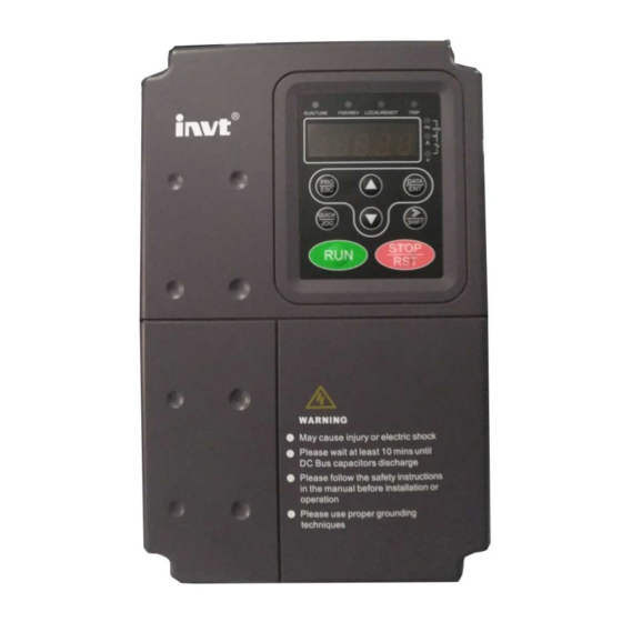
- Page 9 CHV100 Series Close Loop Vector Control Inverter 1.4 Parts Description Figure 1.2 Parts of inverter (15kw and below).
- Page 10 CHV100 Series Close Loop Vector Control Inverter Figure 1.3 Parts of inverters (18.5KW and above). 1.5 Description of Extension Card Thanks to advanced modular design, CHV series inverters can achieve specific functionality by using extension card to meet customer demand. This feature is useful to enhance applicability and flexibility of CHV series inverter.
- Page 11 CHV100 Series Close Loop Vector Control Inverter Extension Card Description Offer RS232 and RS485 dual physical communication interface RS232 adopts standard DB9 master seat. 3-hole RS485 interface, two communication modes can be switched by short-connecting module. Receive high-speed pulse from encoder to realize high- accuracy close-loop vector control.
- Page 13 CHV100 Series Close Loop Vector Control Inverter Figure 1.7 Dimensions (350kw~500W). External Dimensions and Installation Dimensions (380V) Installation Power (mm) (mm) (mm) (mm) (mm) Size Hole (kW) Installation (mm) External Dimension Dimension 1.5~5.5 147.5 237.5 7.5~15 305.5 18.5~30 454.5 37~55 564.5...
- Page 19 CHV100 Series Close Loop Vector Control Inverter Figure 3.7 Disassembly of metal plate cover. Figure 3.8 Open inverter cabinet. .18.
- Page 22 CHV100 Series Close Loop Vector Control Inverter 4.2 Terminal Configuration 4.2.1 Main Circuit Terminals (380VAC) POWER MOTOR Figure 4.2 Main circuit terminals (1.5~5.5kW). POWER MOTOR Figure 4.3 Main circuit terminals (7.5~15kW). POWER MOTOR Figure 4.4 Main circuit terminals (18.5~110kW). POWER MOTOR Figure 4.5...
- Page 23 CHV100 Series Close Loop Vector Control Inverter 4.2.2 Control Circuit Terminals S3 S4 GN D R 01A R 01B R01C H DI1 1 0V CO M C M E C OM HD O AO 1 G ND R02A R 02B R 02C Figure 4.7...
- Page 24 CHV100 Series Close Loop Vector Control Inverter external braking unit between (+) and (-). +24V connect with PW as default setting. If user need external power supply, disconnect +24V with PW and connect PW with external power supply. 4.4 Specifications of Breaker, Cable, Contactor and Reactor 4.4.1 Specifications of breaker, cable and contactor...
- Page 25 CHV100 Series Close Loop Vector Control Inverter Input/output cable Rated current of Circuit Model No. contactor (A) breaker (A) (Coppery wire) (380V or 220V) CHV100-030G-4 CHV100-037G-4 CHV100-045G-4 CHV100-055G-4 CHV100-075G-4 CHV100-090G-4 CHV100-110G-4 CHV100-132G-4 CHV100-160G-4 CHV100-185G-4 CHV100-200G-4 CHV100-220G-4 150x2 CHV100-250G-4 150x2 CHV100-280G-4...
- Page 26 CHV100 Series Close Loop Vector Control Inverter AC Input reactor AC Output reactor DC reactor Model No. Current Inductance Current Inductance Current Inductance (A) (mH) (A) (mH) (A) (mH) CHV100-045G-4 0.13 0.023 0.54 CHV100-055G-4 0.11 0.019 0.45 CHV100-075G-4 0.12 0.014 0.36...
- Page 27 CHV100 Series Close Loop Vector Control Inverter Braking resistor Braking unit Model No. (100% braking torque) Order No. Quantity Specification Quantity 3AC 380V ±15% CHV100-1R5G-4 400Ω/260W CHV100-2R2G-4 150Ω/390W CHV100-004G-4 Build- in CHV100-5R5G-4 100Ω/520W CHV100-7R5G-4 50Ω/1040W CHV100-011G-4 CHV100-015G-4 40Ω/1560W CHV100-018G-4 20Ω/6000W...
- Page 28 CHV100 Series Close Loop Vector Control Inverter Braking unit can be used for braking continuously for 5 minutes. When braking unit is working, temperature of cabinet will be high, user is not allowed to touch to prevent from injury. For more details, please refer to DBU and RBU user manual.
- Page 29 CHV100 Series Close Loop Vector Control Inverter 4.5 Wiring the Main Circuits 4.5.1 Wiring at the side of power supply Circuit breaker It is necessary to connect a circuit breaker which is compatible with the capacity of inverter between 3ph AC power supply and power input terminals (R, S, T ). The capacity of breaker is 1.5~2 times to the rated current of inverter.
- Page 30 CHV100 Series Close Loop Vector Control Inverter • Inverters of 15KW and below have built-in braking unit. In order to dissipate the regenerative energy generated by dynamic braking, the braking resistor should be installed at (+) and PB terminals. The wire length of braking resistor should be less than •...
- Page 31 CHV100 Series Close Loop Vector Control Inverter Figure 4.11 Wiring of regenerative unit. 4.5.5 Wiring of Common DC bus Common DC bus method is widely used in the paper industry and chemical fiber industry which need multi-motor to coordinate. In these applications, some motors are in driving status while some others are in regenerative braking (generating electricity) status.
- Page 32 CHV100 Series Close Loop Vector Control Inverter Figure 4.12 Wiring of common DC bus. Notice: Two inverters must be the same model when connected with Common DC bus method. Be sure they are powered on at the same time. 4.5.6 Ground Wiring (PE) In order to ensure safety and prevent electrical shock and fire, terminal PE must be grounded with ground resistance.
- Page 33 CHV100 Series Close Loop Vector Control Inverter Terminal Description Input impedance: 3.3kΩ High speed pulse or ON-OFF signal input, optical coupling with PW and COM. HDI1(HDI2) Pulse input frequency range: 0~50kHz Input voltage range: 9~30V Input impedance: 1.1kΩ External power supply. +24V terminal is connected to PW terminal as default setting.
- Page 34 CHV100 Series Close Loop Vector Control Inverter Terminal Description RO1C Contact capacity: AC 250V/3A, DC 30V/1A. RO2A、 RO2B、 RO2 relay output: RO2A—common; RO2B—NC; RO2C—NO. RO2C Contact capacity: AC 250V/3A, DC 30V/1A. RO3A、 RO3B、 RO3 relay output: RO3A—common; RO3B—NC; RO3C—NO. RO3C Contact capacity: AC 250V/3A, DC 30V/1A.
- Page 35 CHV100 Series Close Loop Vector Control Inverter attribute of disturbance source and receiver can not be changed. 4.7.2 EMC features of inverter Like other electric or electronic devices, inverter is not only an electromagnetic interference source but also an electromagnetic receiver. The operating principle of inverter determines that it can produce certain electromagnetic interference noise.
- Page 36 CHV100 Series Close Loop Vector Control Inverter 4.7.3.2 Site wiring Power supply wiring: the power should be separated supplied from electrical transformer. Normally it is 5 core wires, three of which are fire wires, one of which is the neutral wire, and one of which is the ground wire.
- Page 37 CHV100 Series Close Loop Vector Control Inverter wire, can not only flow into inverter system but also other devices. It also can make leakage current circuit breaker, relay or other devices malfunction. The value of line-to-line leakage current, which means the leakage current passing through distributed capacitors of input output wire, depends on the carrier frequency of inverter, the length and section areas of motor cables.
- Page 38 CHV100 Series Close Loop Vector Control Inverter 5. OPERATION 5.1 Operating Keypad Description 5.1.1 Keypad schematic diagram Figure 5.1 Keypad schematic diagram. 5.1.2 Button function description Button Name Description Programming Entry or escape of first-level menu. Delete shortcut parameters Enter Key Progressively enter menu and confirm parameters.
- Page 39 CHV100 Series Close Loop Vector Control Inverter Button Name Description Run Key Start to run the inverter in keypad control mode. In running status, restricted by P7.04, can be used to STOP/RESET stop the inverter. When fault alarms, can be used to reset the inverter out of the restriction of P7.04...
- Page 40 CHV100 Series Close Loop Vector Control Inverter Unit indicator Description Frequency unit Current unit Voltage unit Rotating speed unit Percentage 5.1.3.3 Digital Display Have 5 digit LED , which can display all kinds of monitoring data and alarm codes such as reference frequency, output frequency and so on.
- Page 42 CHV100 Series Close Loop Vector Control Inverter UP/DOWN to select different shortcut parameter, and then press DATA/ENT to enter the shortcut second-level menu. The method to modify parameter at the shortcut second-level menu is the same as that at the general third-level menu. If want to return to last display, press QUICK/JOG.
- Page 43 CHV100 Series Close Loop Vector Control Inverter P2.03: motor rated voltage; P2.04: motor rated current P2.05: motor rated power. Notice: the motor should be uncoupled with its load; otherwise, the motor parameters obtained by autotuning may be not correct. Set P0.17 to be 1, and for the detail process of motor parameter autotuning, please refer to the description of Function Code P0.17.
- Page 44 CHV100 Series Close Loop Vector Control Inverter collector output status, PID setting, PID feedback, AI1 voltage, AI2 voltage, AI3 voltage/current, AI4 voltage, HDI1 frequency, HDI2 frequency, step number of simple PLC or multi-step speed, length value. Whether or not to display can be determined by setting the corresponding binary bit of P7.07.
- Page 45 Start Set rated parameter of Selectcontrol mode motor (P2.01~P2.05) Set P0.00 Vector control V/F control Motor parameter autotuning Select runcommandsource Set P0.0 1 Select frequency command source Set P0.03, P0.04, P0.05, P0.06 Set starting frequency P 1.01 Set ACC time P0.11 and DEC time P0.12 Start to run and check Operation is OK...
- Page 46 CHV100 Series Close Loop Vector Control Inverter 6. DETAILED FUNCTION DESCRIPTION 6.1 P0 Group--Basic Function Function Setting Factory Name Description Code Range Setting 0:Sensorless vector control Speed control P0.00 1:Vector control With PG mode 2:V/F control 0: Sensorless vector control: It is widely used for the application which requires high...
- Page 47 CHV100 Series Close Loop Vector Control Inverter The control commands of inverter include: start, stop, forward run, reverse run, jog, fault reset and so on. 0: Keypad (LED extinguished); Both RUN and STOP/RST key are used for running command control. If Multifunction key QUICK/JOG is set as FWD/REV switching function (P7.03 is set to be 1), it will be...
- Page 48 CHV100 Series Close Loop Vector Control Inverter UP/DOWN function can be achieved by keypad (∧ and ∨ ) and multifunctional terminals. Reference frequency can be adjusted by UP/DOWN. UP/DOWN has highest priority which means UP/DOWN is always active no matter which frequency command source is.
- Page 49 CHV100 Series Close Loop Vector Control Inverter acceleration/deceleration time between steps. For details, please refer to description of PA group. 5: Multi-steps speed The reference frequency is determined by PA group. The selection of steps is determined by combination of multi-step speed terminals P5 group.
- Page 50 CHV100 Series Close Loop Vector Control Inverter 2. HDI2 The principle is the same as AI1. Function Setting Factory Name Description Code Range Setting 0: A Frequency 1: B P0.06 command 2: A+B selection 3: Max(A, B) This parameter can be used to select the reference frequency command.
- Page 51 CHV100 Series Close Loop Vector Control Inverter Actual acceleration time and deceleration time are determined by maximum frequency. Please refer to description of P0.11 and P0.12. Function Setting Factory Name Description Code Range Setting Upper P0.08 P0.09~P0.07 P0.09~P0.07 50.00Hz frequency limit...
- Page 52 CHV100 Series Close Loop Vector Control Inverter Figure 6.2 Acceleration and Deceleration time. When the reference frequency is equal to the maximum frequency, the actual acceleration and deceleration time will be equal to the P0.11 and P0.12 respectively. When the reference frequency is less than the maximum frequency, the actual acceleration and deceleration time will be less than the P0.11 and P0.12 respectively.
- Page 53 CHV100 Series Close Loop Vector Control Inverter direction of motor may be changed. Please be cautious to use. If P0.13 is set to 2, user can not change rotation direction of motor by QUICK/JOG or terminal. Function Setting Factory Name...
- Page 54 CHV100 Series Close Loop Vector Control Inverter Function Setting Factory Name Description Code Range Setting 0: Fixed P0.15 PWM mode 1: Random 0: Fixed: The noise frequency of motor is fixed. 1: Random: This mode can restrain the noise of motor effectively, but may increase the harmonic of motor.
- Page 55 CHV100 Series Close Loop Vector Control Inverter and finally LED displays the same as stop status. When “-TUN-” is flickering, autotune can be quited by pressing PRG/ESC. During autotune, pressing STOP/RST can stop the autotune. Notice: Only keypad can control the autotuning. P0.17 will restore to 0 automatically when the autotuning is finished or cancelled.
- Page 56 CHV100 Series Close Loop Vector Control Inverter then start running to its reference frequency based on current speed. This can realize smooth start of rotating motor with big inertia load when instantaneous power off. Notice: It only applies on the inverter of 7.5kW and above.
- Page 57 CHV100 Series Close Loop Vector Control Inverter the DC braking current, the greater the braking torque. Function Setting Factory Name Description Code Range Setting Acceleration 0:Linear P1.05 /Deceleration 1:S curve mode 0: Linear: Output frequency will increase or decrease with fixed acceleration or deceleration time.
- Page 58 CHV100 Series Close Loop Vector Control Inverter Function Setting Factory Name Description Code Range Setting 0:Deceleration to stop P1.08 Stop Mode 1:Coast to stop 0: Deceleration to stop When the stop command takes effect, the inverter decreases the output frequency according to P1.05 and the selected acceleration/deceleration time till stop.
- Page 59 CHV100 Series Close Loop Vector Control Inverter Figure 6.6 DC braking diagram. Function Setting Factory Name Description Code Range Setting Dead time of P1.13 0.0~3600.0s 0.0~3600.0 0.0s FWD/REV Set the hold time at zero frequency in the transition between forward and reverse running.
- Page 60 CHV100 Series Close Loop Vector Control Inverter 1: Stop: This parameter is used to prevent motor running at low speed for a long time. 2: Stand-by: Inverter will stand-by when the running frequency is less than P0.09. When the reference frequency is higher than or equal to P0.09 again, the inverter will start to run automatically.
- Page 61 CHV100 Series Close Loop Vector Control Inverter Function Setting Factory Name Description Code Range Setting Motor rated Depend P2.03 0~3000V 0~3000 voltage on model Motor rated Depend P2.04 0.1~2000.0A 0.1~2000.0 current on model Depend P2.05 Motor rated power 1.5~900.0kW 1.5~900.0...
- Page 62 CHV100 Series Close Loop Vector Control Inverter Function Setting Factory Name Description Code Range Setting ASR integral time P3.01 0.01~10.00s 0.01~10.00 0.50s ASR switching P3.02 0.00Hz~P3.05 0.00~P3.05 5.00Hz point 1 ASR proportional P3.03 0~100 0~100 gain K ASR integral time P3.04...
- Page 63 CHV100 Series Close Loop Vector Control Inverter The system's dynamic response can be faster if the proportion gain K is increased; However, if K is too large, the system tends to oscillate. The system dynamic response can be faster if the integral time K is decreased;...
- Page 64 CHV100 Series Close Loop Vector Control Inverter Function Setting Factory Name Description Code Range Setting PG direction 0: Forward P3.11 selection 1: Reverse P3.10 defines the number of pulse per cycle of PG or encoder. Notice: When P0.00 is set to be 1, P3.10 must be set correctly according to the encoder parameter, otherwise the motor will run abnormally.
- Page 65 CHV100 Series Close Loop Vector Control Inverter Torque control can be switched to speed control, vice versa. Switching by multifunctional terminal: For example, if torque setting source is AI1 (P3.12=2), the value of multifunction terminal S5 is set to 31 (Disable torque control).
- Page 66 CHV100 Series Close Loop Vector Control Inverter Figure 6.10 Multiple V/F curve diagram. Function Setting Factory Name Description Code Range Setting 0.0%: auto P4.01 Torque boost 0.0~10.0% 1.0% 0.1%~10.0% Torque boost 0.0%~50.0% P4.02 0.0~50.0% 20.0% cut-off (motor rated frequency) Torque boost will take effect when output frequency is less than cut-off frequency of torque boost (P4.02).
- Page 67 CHV100 Series Close Loop Vector Control Inverter Function Setting Factory Name Description Code Range Setting P4.03 V/F frequency 1 0.00Hz~ P4.05 0.00~P4.05 5.00Hz P4.04 V/F voltage 1 0.0%~100.0% 0.0~100.0 10.0% P4.03~ P4.05 V/F frequency 2 P4.03~ P4.07 30.00Hz P4.07 P4.06 V/F voltage2 0.0%~100.0%...
- Page 68 CHV100 Series Close Loop Vector Control Inverter load change can be reduced. The value of compensated slip is dependent on the motor’s − 4.09 * / 60 rated slip which can be calculated as: . Where motor rated frequency (P2.01), is motor rated speed (P2.02), and...
- Page 69 CHV100 Series Close Loop Vector Control Inverter 6.6 P5 Group--Input Terminals Function Setting Factory Name Description Code Range Setting 0: HDI1 and HDI2 are high speed pulse input. 1: HDI1 is ON-OFF input, HDI2 is high speed pulse input. P5.00...
- Page 70 CHV100 Series Close Loop Vector Control Inverter Function Setting Factory Name Description Code Range Setting function terminal S6 Terminal Programmable multifunction P5.09 0~55 function terminal S7 Terminal Programmable multifunction P5.10 0~55 function terminal S8 Terminal Programmable multifunction P5.11 0~55 function terminal Notice: P5.07 is only used when P5.00 is set to be 1 or 3.
- Page 71 CHV100 Series Close Loop Vector Control Inverter Setting Function Description value DOWN command Clear UP/DOWN Use this terminal to clear UP/DOWN setting. Please refer to description of P0.02. Switch between P0.06 A and B Terminal action Switch between 13 valid...
- Page 72 CHV100 Series Close Loop Vector Control Inverter Setting Function Description value 4 groups of ACC/DEC time can be selected by the combination of these two terminals. ACC/DEC time ACC/DEC time ACC/DEC time ACC/DEC time selection 2 selection1 selection1 ACC/DEC time 0 (P0.11、P0.12)
- Page 73 CHV100 Series Close Loop Vector Control Inverter Setting Function Description value 32~52 Reserved Reserved for water supply control. Combine with FWD/REV operation to be 3-wire jog control. 3-wire jog control Command Forward running Reverse running Forward jogging Reverse jogging 54~55...
- Page 75 CHV100 Series Close Loop Vector Control Inverter Figure 6.16 3-wire control mode 2. Notice: When 2-wire control mode is active, the inverter will not run in following situation even if FWD/REV terminal is enabled: Coast to stop (press RUN and STOP/RST at the same time).
- Page 76 CHV100 Series Close Loop Vector Control Inverter lower limit and upper limit, it will be regarded as the upper limit or lower limit. The analog input AI1 can only provide voltage input, and the range is 0V~10V. For different applications, the corresponding value of 100.0% analog setting is different.
- Page 77 CHV100 Series Close Loop Vector Control Inverter Function Setting Factory Name Description Code Range Setting AI3 filter time P5.29 0.00s~10.00s 0.00~10.00 0.10s constant P5.30 AI4 lower limit 0.00V~10.00V 0.00~10.00 0.00V AI4 lower limit P5.31 corresponding -100.0%~100.0% -100.0~100.0 0.0% setting P5.32 AI4 upper limit 0.00V~10.00V...
- Page 78 CHV100 Series Close Loop Vector Control Inverter Function Setting Factory Name Description Code Range Setting P5.39 HDI1 upper limit 0.0 kHz ~50.0kHz 0.0~50.0 50.0kHz HDI1 upper limit P5.40 -100.0%~100.0% -100.0~100.0 100.0% corresponding setting HDI1 filter time P5.41 0.00s~10.00s 0.00~10.00 0.10s constant P5.42...
- Page 79 CHV100 Series Close Loop Vector Control Inverter Function Setting Factory Name Description Code Range Setting HDO ON-OFF P6.03 Open-collector output 0~31 output selection Relay 1 output P6.04 Relay output 0~31 selection Relay 2 output P6.05 Relay output 0~31 selection Relay 3 output P6.06...
- Page 80 CHV100 Series Close Loop Vector Control Inverter Setting Function Description Value Upper frequency ON: Running frequency reaches the value of P0.08. limit reached Lower frequency ON: Running frequency reaches the value of P0.09. limit reached Ready ON: Inverter is ready (no fault, power is ON).
- Page 81 CHV100 Series Close Loop Vector Control Inverter Setting Function Range Value AI1 voltage 0~10V AI2 voltage/current 0~10V/0~20mA AI3 voltage -10V~10V AI4 voltage 0~10V HDI1 frequency 0.1~50.0kHz HDI2 frequency 0.1~50.0kHz Length value 0~preset length (P8.19) Count value 0~preset count value (P8.22)
- Page 82 CHV100 Series Close Loop Vector Control Inverter Figure 6.18 Relationship between AO and corresponding setting. Function Setting Factory Name Description Code Range Setting P6.18 HDO lower limit 0.0%~100.0% 0.0~100.0 0.0% HDO lower limit P6.19 corresponding 0.0 ~ 50.0kHz 0.0~50.0 0.0kHz output P6.20...
- Page 83 CHV100 Series Close Loop Vector Control Inverter P7.00 is set to be 00000, user’s password set before will be cleared and the password protection function will be disabled. After the password has been set and becomes valid, the user can not access menu if the user’s password is not correct.
- Page 84 CHV100 Series Close Loop Vector Control Inverter Function Setting Factory Name Description Code Range Setting 0: Valid when keypad control (P0.01=0) 1: Valid when keypad or terminal control (P0.01=0 or STOP/RST P7.04 function selection 2: Valid when keypad or communication control (P0.01=0 or 2)
- Page 85 CHV100 Series Close Loop Vector Control Inverter When LCD keypad is connected, P7.05 must be set to be 0. Function Setting Factory Name Description Code Range Setting Running status P7.06 0~0xFFFF 0~0xFFFF 0x00FF display selection P7.06 defines the parameters that can be displayed by LED in running status. If Bit is 0, the parameter will not be displayed;...
- Page 86 CHV100 Series Close Loop Vector Control Inverter BIT7 BIT6 BIT5 BIT4 BIT3 BIT2 BIT1 BIT0 Output Input DC bus Reference PID preset terminal terminal feedback voltage frequency status status BIT15 BIT14 BIT13 BIT12 BIT11 BIT10 BIT9 BIT8 Step No. of...
- Page 87 CHV100 Series Close Loop Vector Control Inverter Function Setting Factory Name Description Code Range Setting P7.15 Latest fault type 0~30 0~30 These parameters record three recent fault types. For details, please refer to description of chapter 7. Function Setting Factory...
- Page 88 CHV100 Series Close Loop Vector Control Inverter 6.9 P8 Group --Enhanced Function Function Setting Factory Name Description Code Range Setting P8.00 Acceleration time 1 0.0~3600.0s 0.0~3600.0 20.0s P8.01 Deceleration time 1 0.0~3600.0s 0.0~3600.0 20.0s P8.02 Acceleration time 2 0.0~3600.0s 0.0~3600.0 20.0s...
- Page 89 CHV100 Series Close Loop Vector Control Inverter following figure. Figure 6.20 Skip frequency diagram. Function Setting Factory Name Description Code Range Setting Traverse P8.12 0.0~100.0% 0.0~100.0 0.0% amplitude P8.13 Jitter frequency 0.0~50.0% 0.0~50.0 0.0% Rise time of P8.14 0.1~3600.0s 0.1~3600.0 5.0s...
- Page 90 CHV100 Series Close Loop Vector Control Inverter Rise time of traverse: Indicates the time rising from the lowest traverse frequency to the highest traverse frequency. Fall time of traverse: Indicates the time falling from the highest traverse frequency to the lowest traverse frequency.
- Page 91 CHV100 Series Close Loop Vector Control Inverter Actual length (P8.20) = Accumulated input pulse number / Number of pulse per cycle (P8.21). When the value of P8.20 exceeds the value of P8.19, if multifunctional output terminal is set to be 11 (Length reached), ON signal will be output.
- Page 92 CHV100 Series Close Loop Vector Control Inverter running time reaches the preset running time, it will output an ON-OFF signal. Function Setting Factory Name Description Code Range Setting P8.25 FDT level 0.00~ P0.07 0.00~ P0.07 50.00Hz P8.26 FDT lag 0.0~100.0% 0.0~100.0...
- Page 93 CHV100 Series Close Loop Vector Control Inverter Figure 6.24 Frequency arriving detection diagram. Function Setting Factory Name Description Code Range Setting P8.28 Droop control 0.00~10.00Hz 0.00~10.00 0.00Hz When several motors drive the same load, each motor's load is different because of the difference of motor's rated speed.
- Page 94 CHV100 Series Close Loop Vector Control Inverter Function Setting Factory Name Description Code Range Setting 0: Invalid Auxiliary motor 1: Motor 1 valid P8.29 selection 2: Motor 2 valid 3: Both valid Auxiliary motor1 P8.30 0.0~3600.0s 0.0~3600.0 5.0s START/STOP delay time Auxiliary motor2 P8.31...
- Page 95 CHV100 Series Close Loop Vector Control Inverter Figure 6.26 Simple water-supply function logical diagram. Notice: Delay time of start auxiliary motor and stop auxiliary motor are the same. PID control (P0.03=6) is necessary for simple water supply control. P1.14 should not be set to be 1.
- Page 96 CHV100 Series Close Loop Vector Control Inverter The value of P8.32 is corresponding to the DC bus voltage at rated input voltage. Function Setting Factory Name Description Code Range Setting Low-frequency threshold of P8.33 0~9999 0~9999 1000 restraining oscillation High-frequency threshold of P8.34...
- Page 97 CHV100 Series Close Loop Vector Control Inverter Function Setting Factory Name Description Code Range Setting 2: AI2 3: AI3 4: AI4 5: HDI1 6: HDI2 7: Communication 8: Simple PLC Keypad PID P9.01 -100.0%~100.0% -100.0~100.0 0.0% preset 0: AI1 1: AI2...
- Page 98 CHV100 Series Close Loop Vector Control Inverter Function Setting Factory Name Description Code Range Setting Proportional gain P9.04 0.00~100.00 0.00~100.00 0.10 (Kp) P9.05 Integral time (Ti) 0.01~10.00s 0.01~10.00 0.10s Differential time P9.06 0.00~10.00s 0.00~10.00 0.00s (Td) Optimize the responsiveness by adjusting these parameters while driving an actual load.
- Page 99 CHV100 Series Close Loop Vector Control Inverter Figure 6.29 Reducing long-cycle oscillation diagram. Reducing short-cycle oscillation If the oscillation cycle is short and oscillation occurs with a cycle approximately the same as the differential time setting, it means that the differential operation is strong. The oscillation will be reduced as the differential time is shortened.
- Page 100 CHV100 Series Close Loop Vector Control Inverter Figure 6.31 Relationship between bias limit and output frequency. Function Setting Factory Name Description Code Range Setting PID output filter P9.09 0.00~10.00s 0.00~10.00 0.00 time The bigger the filter time, the better the immunity capability, but the response becomes slow, vice versa.
- Page 101 CHV100 Series Close Loop Vector Control Inverter If P0.03 is set to be 5, 16 steps are available for multi-step speed. Otherwise only 15 steps are available (step 1~15). Function Setting Factory Name Description Code Range Setting 0: Stop after one cycle 1: Hold last frequency after PA.00...
- Page 102 CHV100 Series Close Loop Vector Control Inverter Function Setting Factory Name Description Code Range Setting PA.02 Multi-step speed 0 -100.0~100.0% -100.0~100.0 0.0% Step running PA.03 0.0~6553.5s(h) 0.0~6553.5 0.0s time PA.04 Multi-step speed 1 -100.0~100.0% -100.0~100.0 0.0% Step running PA.05 0.0~6553.5s(h) 0.0~6553.5...
- Page 103 CHV100 Series Close Loop Vector Control Inverter Function Setting Factory Name Description Code Range Setting time PA.24 Multi-step speed 11 -100.0~100.0% -100.0~100.0 0.0% Step running PA.25 0.0~6553.5s(h) 0.0~6553.5 0.0s time PA.26 Multi-step speed 12 -100.0~100.0% -100.0~100.0 0.0% Step running PA.27 0.0~6553.5s(h)
- Page 104 CHV100 Series Close Loop Vector Control Inverter Figure 6.33 Multi-steps speed operation diagram. Terminal Multi-step Multi-step Multi-step Multi-step speed speed speed speed Step reference1 reference2 reference3 reference4 .103.
- Page 105 CHV100 Series Close Loop Vector Control Inverter Function Setting Factory Name Description Code Range Setting ACC/DEC time PA.34 selection for step 0~65535 0~65535 ACC/DEC time PA.35 selection for step 0~65535 0~65535 8~15 These parameters are used to determine the ACC/DEC time from one step to next step.
- Page 106 CHV100 Series Close Loop Vector Control Inverter Low byte BIT 0 BIT 1 BIT 2 BIT 3 BIT 4 BIT 5 BIT 6 BIT 7 PA.34 PA.35 High byte BIT 8 BIT 9 BIT 10 BIT 11 BIT 12 BIT 13...
- Page 107 CHV100 Series Close Loop Vector Control Inverter Function Setting Factory Name Description Code Range Setting Motor overload PB.03 20.0%~120.0% 20.0~120.0 100.0% protection current Figure 6.34 Motor overload protection curve. The value can be determined by the following formula: Motor overload protection current = (motor rated current / inverter rated current) * 100%...
- Page 108 CHV100 Series Close Loop Vector Control Inverter Function Setting Factory Name Description Code Range Setting Overload PB.06 pre-warning delay 0.0~30.0s 0.0~30.0 5.0s time The value of PB.05 determines the pre-warning category, such as motor overload (OL1) or inverter overload (OL2).
- Page 109 CHV100 Series Close Loop Vector Control Inverter too small to achieve voltage compensation effect. So please set PB.08 according to load inertia and the actual load. Function Setting Factory Name Description Code Range Setting Over-voltage stall 0: Disabled PB.09 protection...
- Page 110 CHV100 Series Close Loop Vector Control Inverter output frequency rise rate because of too big load. If no measures to take, inverter will trip caused by over-current. The principle of over-current protection is to detect the output current of inverter during inverter operation and compare it with over-current stall threshold determined by PB.12.
- Page 111 CHV100 Series Close Loop Vector Control Inverter Function Setting Factory Name Description Code Range Setting 6: HDI 2 7: communication 0: Keypad: User can set the value of P0.08 as upper frequency limit. 1~7: Please refer to description of P0.03.
- Page 112 CHV100 Series Close Loop Vector Control Inverter 7. TROUBLE SHOOTING 7.1 Fault and trouble shooting Fault Code Fault Type Reason Solution 1. Acc/Dec time is too 1. Increase Acc/Dec OUT1 IGBT Ph-U fault short. time. 2. IGBT module fault. 2. Ask for support.
- Page 113 CHV100 Series Close Loop Vector Control Inverter Fault Code Fault Type Reason Solution input power supply are loose. 4.Voltage fluctuations in power supply are too large. 1. Motor drive heavy load 1. Select variable at low speed for a long frequency motor.
- Page 114 CHV100 Series Close Loop Vector Control Inverter Fault Code Fault Type Reason Solution 3. Output terminals are loose. 1.Ambient temperature is 1. Install cooling unit. too high. Rectify overheat 2.Near heat source. 2. Remove heat source. 3. Replace cooling fan 3.
- Page 115 CHV100 Series Close Loop Vector Control Inverter Fault Code Fault Type Reason Solution 1. Serious disturbance 1. Press STOP/RST to cause control board reset or install input filter OPSE System fault unable to operate properly. at input side. 2. Noise cause control 2.
- Page 116 CHV100 Series Close Loop Vector Control Inverter voltage or not with multi-meter. If the power supply has problem, inspect and solve Inspect whether the three-phase rectify bridge is in good condition or not. If the rectification bridge is burst out, ask for support.
- Page 118 CHV100 Series Close Loop Vector Control Inverter Items to be Main inspections Criteria hecked Inspection content Frequency Means/methods smooth operation ⑴ point without vibration. ⑴ vibration cooling thermometer ⑵ n is working in good ⑴ ⑵ Inverter and heating comprehensive condition.
- Page 119 CHV100 Series Close Loop Vector Control Inverter When supplying AC power to the drive, use a voltage regulator to raise the input voltage to rated input voltage gradually. The drive should be powered for 5 hours without load. 7. Before performing insulation tests, all main circuit input/output terminals should be short-circuited with conductors.
- Page 120 CHV100 Series Close Loop Vector Control Inverter 9. LIST OF FUNCTION PARAMETERS Notice: PE group is factory reserved, users are forbidden to access these parameters. The column “Modify” determines the parameter can be modified or not. “○” indicates that this parameter can be modified all the time.
- Page 121 CHV100 Series Close Loop Vector Control Inverter Function Factory Name Description Modify LCD Display Code Setting 0: Keypad 1: AI1 2. AI3 Frequency A 3: HDI1 FREQ P0.03 ◎ command source 4:Simple PLC SOURCE A 5. Multi-Step speed 6: PID...
- Page 122 CHV100 Series Close Loop Vector Control Inverter Function Factory Name Description Modify LCD Display Code Setting Depend CARRIER P0.14 Carrier frequency 1.0~16.0kHz ○ on model FREQ 0:Fixed P0.15 PWM mode PWM MODE ○ 1:Random Carrier frequency 0: Disabled AUTO P0.16...
- Page 123 CHV100 Series Close Loop Vector Control Inverter Function Factory Name Description Modify LCD Display Code Setting Start section of S 0.0~40.0% START P1.06 30.0% ◎ curve (ACC/DEC time) SECTION End section of S 0.0~40.0% P1.07 30.0% ◎ curve (ACC/DEC time)
- Page 124 CHV100 Series Close Loop Vector Control Inverter Function Factory Name Description Modify LCD Display Code Setting MOTOR Motor rated 1460 P2.02 0~36000rpm RATE ◎ speed SPEED Motor rated Depend MOTOR P2.03 0~3000V ◎ voltage on model RATE VOLT Motor rated...
- Page 125 CHV100 Series Close Loop Vector Control Inverter Function Factory Name Description Modify LCD Display Code Setting ASR switching P3.05 P3.02~P0.07 10.00Hz SWITCHPOI ○ point 2 ACR proportional P3.06 0~65535 ACR P ○ gain P ACR integral gain P3.07 0~65535 ACR I ○...
- Page 126 CHV100 Series Close Loop Vector Control Inverter Function Factory Name Description Modify LCD Display Code Setting 0:Linear curve 1: User-defined curve 2: Torque_stepdown V/F curve curve (1.3 order) P4.00 V/F CURVE ◎ selection 3: Torque_stepdown curve (1.7 order) 4: Torque_stepdown curve (2.0 order)
- Page 127 CHV100 Series Close Loop Vector Control Inverter Function Factory Name Description Modify LCD Display Code Setting P5 Group: Input Terminals 0: HDI1 and HDI2 are high speed pulse input. 1: HDI1 is ON-OFF input, HDI2 is high speed pulse input.
- Page 128 CHV100 Series Close Loop Vector Control Inverter Function Factory Name Description Modify LCD Display Code Setting 16: Multi-step speed reference1 S7 Terminal P5.10 ◎ 17: Multi-step speed function FUNCTION reference2 18: Multi-step speed reference3 19: Multi-step speed reference4 20: Multi-step speed...
- Page 129 CHV100 Series Close Loop Vector Control Inverter Function Factory Name Description Modify LCD Display Code Setting 0: 2-wire control mode 1 FWD/REV control 1: 2-wire control mode 2 FWD/REV P5.13 ◎ mode CONTROL 2: 3-wire control mode 1 3: 3-wire control mode 2...
- Page 130 CHV100 Series Close Loop Vector Control Inverter Function Factory Name Description Modify LCD Display Code Setting AI3 lower limit AI3 LOW P5.26 corresponding -100.0%~100.0% 0.0% ○ SETTING setting P5.27 AI3 upper limit -10.00V ~10.00V 10.00V AI3 UP LIMIT ○ AI3 upper limit AI3 UP P5.28...
- Page 131 CHV100 Series Close Loop Vector Control Inverter Function Factory Name Description Modify LCD Display Code Setting HDI1 upper limit HDI1 UP P5.40 corresponding -100.0%~100.0% 100.0% ○ SETTING setting HDI1 filter time HDI1 FILTER P5.41 0.00s~10.00s 0.10s ○ constant TIME HDI2 LOW P5.42...
- Page 132 CHV100 Series Close Loop Vector Control Inverter Function Factory Name Description Modify LCD Display Code Setting reached 10: Specified count value reached 11: Length reached 12: PLC cycle completed 13: Running time reached 14: Upper frequency limit reached Relay 3 output 15: Lower frequency limit P6.06...
- Page 133 CHV100 Series Close Loop Vector Control Inverter Function Factory Name Description Modify LCD Display Code Setting AO1 LOW P6.10 AO1 lower limit 0.0%~100.0% 0.0% ○ LIMIT AO1 lower limit AO1 LOW P6.11 corresponding 0.00V ~10.00V 0.00V ○ OUTPUT output AO1 UP P6.12...
- Page 134 CHV100 Series Close Loop Vector Control Inverter Function Factory Name Description Modify LCD Display Code Setting USER P7.00 User password 0~65535 ○ PASSWORD LCD language 0: Chinese LANGUAGE P7.01 ○ selection 1: English SELECT 0: Invalid 1: Upload parameters to P7.02...
- Page 135 CHV100 Series Close Loop Vector Control Inverter Function Factory Name Description Modify LCD Display Code Setting 1.Output frequency 2.Reference frequency 3.DC bus voltage 4.Output voltage 5.Output current Other parameters display is determined by 16 bit binary digit BIT0: Rotation speed...
- Page 136 CHV100 Series Close Loop Vector Control Inverter Function Factory Name Description Modify LCD Display Code Setting BIT0: Reference frequency BIT1: DC bus voltage BIT2: Input terminal status BIT3: Output terminal status BIT4: PID preset BIT5: PID feedback Stop status STOP BIT6: AI1 P7.07...
- Page 137 CHV100 Series Close Loop Vector Control Inverter Function Factory Name Description Modify LCD Display Code Setting 0: Not fault 1: IGBT Ph-U fault(OUT1) 2: IGBT Ph-V fault(OUT2) 3: IGBT Ph-W fault(OUT3) Third latest fault 3rd LATEST P7.13 ● 4: Over-current when...
- Page 138 CHV100 Series Close Loop Vector Control Inverter Function Factory Name Description Modify LCD Display Code Setting (SPI) 14: Output phase failure (SPO) 15: Rectify overheat (OH1) 16: IGBT overheat (OH2) 17: External fault (EF) 18: Communication fault (CE) 19: Current detection fault...
- Page 139 CHV100 Series Close Loop Vector Control Inverter Function Factory Name Description Modify LCD Display Code Setting Input terminal FAULT Sx P7.19 status at current ● STATUS fault Output terminal FAULT DO P7.20 status at current ● STATUS fault P8 Group: Enhanced Function Acceleration time P8.00...
- Page 140 CHV100 Series Close Loop Vector Control Inverter Function Factory Name Description Modify LCD Display Code Setting JITTER P8.13 Jitter frequency 0.0~50.0% 0.0% ○ FREQ Rise time of TRAV RISE P8.14 0.1~3600.0s 5.0s ○ traverse TIME Fall time of TRAV FALL P8.15...
- Page 141 CHV100 Series Close Loop Vector Control Inverter Function Factory Name Description Modify LCD Display Code Setting 0: Invalid Auxiliary motor 1: Motor 1 valid AUXILIARY P8.29 ◎ selection MOTOR 2: Motor 2 valid 3: Both valid Auxiliary motor1 MOTOR 1 P8.30...
- Page 142 CHV100 Series Close Loop Vector Control Inverter Function Factory Name Description Modify LCD Display Code Setting 0: AI1 1: AI2 2: AI3 3: AI4 PID feedback 4: AI1-AI2 P9.02 ○ source selection FEEDBACK 5: AI3-AI4 6: HDI1 7: HDI2 8: HDI1-HDI2...
- Page 143 CHV100 Series Close Loop Vector Control Inverter Function Factory Name Description Modify LCD Display Code Setting 0: Not saved Simple PLC 1: Saved STATUS PA.01 status saving ○ SAVING 2: Not saved when power selection off, saved when stop Multi-step speed MULTI-SPEE PA.02...
- Page 144 CHV100 Series Close Loop Vector Control Inverter Function Factory Name Description Modify LCD Display Code Setting Multi-step speed MULTI-SPEE PA.16 -100.0~100.0% 0.0% ○ Step running RUNNING PA.17 0.0~6553.5s(h) 0.0s ○ time TIME 7 Multi-step speed MULTI-SPEE PA.18 -100.0~100.0% 0.0% ○...
- Page 145 CHV100 Series Close Loop Vector Control Inverter Function Factory Name Description Modify LCD Display Code Setting Multi-step speed MULTI-SPEE PA.32 -100.0~100.0% 0.0% ○ D 15 Step running RUNNING PA.33 0.0~6553.5s(h) 0.0s ○ time TIME 15 ACC/DEC time 0~7 TIME PA.34...
- Page 146 CHV100 Series Close Loop Vector Control Inverter Function Factory Name Description Modify LCD Display Code Setting 0: Always detect relative to motor rated current 1: Detect while constant speed relative to motor Overload rated current OL WARN PB.05 pre-warning ◎...
- Page 147 CHV100 Series Close Loop Vector Control Inverter Function Factory Name Description Modify LCD Display Code Setting 0: 1200BPS 1: 2400BPS Baud rate 2: 4800BPS PC.01 BAUD RATE ○ selection 3: 9600BPS 4: 19200BPS 5: 38400BPS .146.
- Page 148 CHV100 Series Close Loop Vector Control Inverter Function Factory Name Description Modify LCD Display Code Setting 0: RTU, 1 start bit, 8 data bits, no parity check, 1 stop bit. 1: RTU, 1 start bit, 8 data bits, even parity check, 1 stop bit.
- Page 149 CHV100 Series Close Loop Vector Control Inverter Function Factory Name Description Modify LCD Display Code Setting Communication COM DELAY PC.03 0~200ms ○ delay time TIME Communication 0.0(invalid) PC.04 0.0s ○ timeout delay 0.1~100.0s TIMEOUT 0: Enabled RESPONSE PC.05 Response action ○...
Need help?
Do you have a question about the CHV100 Series and is the answer not in the manual?
Questions and answers