Table of Contents
Advertisement
Quick Links
Advertisement
Table of Contents

Related Manuals for Toshiba RemotEye 4


Summary of Contents for Toshiba RemotEye 4
- Page 1 RemotEye User Manual Document Number: 90988-007 September 2018...
-
Page 2: About This Manual
ABOUT THIS MANUAL This manual was written by the TOSHIBA Engineering and Marketing Groups. These groups are tasked with providing technical documentation for the RemotEye 4 system. Every effort has been made to provide accurate and concise information to you, our customer. -
Page 3: Contacting Toshiba's Customer Support Center
CONTACTING TOSHIBA’S CUSTOMER SUPPORT CENTER TOSHIBA’s Customer Support Center can be contacted to obtain help in resolving any RemotEye 4 system problem that you may experience or to provide application information. The Support Center can be reached at 855-803-7087 (toll free) or 713-466-0277. The center is open from 8 a.m. to 5 p.m. - Page 4 This Page Intentionally Left Blank RemotEye 4 User Manual – 90988-007...
-
Page 5: Table Of Contents
INTRODUCTION ........................... 15 PURPOSE & MANUAL OVERVIEW ...................... 15 APPLICABLE SPECIFICATIONS ......................15 UPS COMPATIBILITY ..........................16 PACKAGE CONTENTS ........................... 16 REMOTEYE 4 LAYOUT AND LED INDICATORS ................17 2.5.1 Hard Reset Button ..........................18 FEATURES ..............................20 2.6.1 HTTP Web Access ..........................20 2.6.2... - Page 6 MOBILE-FRIENDLY WEB INTERFACE ................. 61 DISPLAY AND NAVIGATION ....................... 61 ALERT CENTER ............................62 PROTECTED CLIENTS ..........................62 REMOTEYE 4 CONSOLE MENU NAVIGATION ..............63 MAIN MENU DESCRIPTION ........................66 REMOTEYE 4 CARD SETTINGS ......................67 9.2.1 IP, Time and System Group ......................... 68 9.2.2...
- Page 7 UPS EVENTS RECORDS PAGE ......................89 REMOTEYE 4 EVENTS RECORDS PAGE .................... 89 ACKNOWLEDGED ALERTS RECORDS PAGE ................... 90 EMD HISTORY LOG ..........................90 EMD EXTENDED HISTORY LOG ......................90 REMOTEYE APPLICATION PROGRAMS ................91 REMOTEYE CLIENT SHUTDOWN SOFTWARE FOR ESXI 5/5.1/5.5/6.0 ......... 91 11.1.1...
- Page 8 APPENDIX Q – SNMP MIB OID’S FOR T1000 (1-3 KVA) .............. 250 APPENDIX R – SNMP MIB OID’S FOR 5000 (3P1) ................. 252 APPENDIX S – SNMP MIB OID’S FOR G9000/G2020 V2 ............... 256 APPENDIX T – ADDITIONAL RS-485 CONNECTION INFORMATION ........260 RemotEye 4 User Manual – 90988-007...
-
Page 9: List Of Figures
Figure 3-1 RemotEye 4 MAC Address Location ....................... 25 Figure 3-2 RemotEye 4 Location in 1600XP ......................25 Figure 3-3 RemotEye 4 in 4300 and 4400 UPS ......................26 Figure 3-4 RemotEye 4 in G9000/G2020 UPS ......................26 Figure 3-5 RemotEye 4 in G9000 1000kVA ......................27 Figure 4-1 RemotEye 4 Network Connection Example ..................... - Page 10 Figure 11-9 vSphere Management Asistant Screen Shot .................... 96 Figure 11-10 VM Remote Shutdown Test ........................97 Figure 11-11 RemotEye 4 Save Log Utility RemotEye 4 – Auto Save Log Tab ............. 100 Figure 11-12 RemotEye 4 Save Log Utility RemotEye 4 – Selecting ............... 101 Figure 11-13 RemotEye 4 Save Log Utility –...
-
Page 11: List Of Tables
Table 10-1 History Log Availability .......................... 81 Table 10-2 UPS History Summary Page Availability ....................81 Table 10-4 RemotEye 4 UPS Warning Codes ......................89 Table 11-1 Tupgrade Toolbar Functions ........................105 Table 12-1 RemotEye 4 System Specifications ......................106 Table 12-2 RemotEye 4 LED Indications ......................... - Page 12 This Page Intentionally Left Blank RemotEye 4 User Manual – 90988-007...
-
Page 13: General Safety Instructions
1.2.1 Electrical Hazard Symbol A symbol which indicates a hazard of injury from electrical shock or burn. It is comprised of an equilateral triangle enclosing a lightning bolt. RemotEye 4 User Manual – 90988-007... -
Page 14: Explosion Hazard Symbol
WARNING Misuse of this equipment could result in injury and equipment damage. In no event will Toshiba Corporation be responsible or liable for either indirect or consequential damage or injury that may result from the misuse of this equipment. -
Page 15: Introduction
Modbus TCP/RTU (Transmission Control Protocol/Remote Terminal Unit) BACnet IP/MSTP (Internet Protocol /Master Slave Token Passing) This user manual describes how to install, configure, and operate the RemotEye 4. The RemotEye 4 connects to the network via either a RJ-45 or a RS-485 connection. -
Page 16: Ups Compatibility
UPS COMPATIBILITY The RemotEye 4 is compatible with the following Toshiba UPS product lines: T1000 Single Phase UPS Family T1000 (1-3kVA) Single Phase UPS Family 1600XP/XPi Single Phase UPS Family (NOTE: The 1600XP and 1600XPi are identical except for case color (XP is off-white, and XPi is black) and the XPi comes pre-loaded with the RemotEye 4) ... -
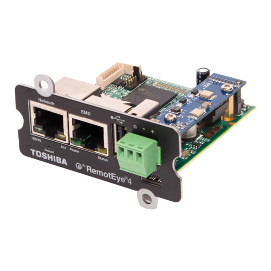
Page 17: Remoteye 4 Layout And Led Indicators
Connects to a workstation USB A port with the provided USB adapter cable. Restart button (Access Restarts RemotEye 4 display only. (Does not restart the UPS) (The Restart button through faceplate) is behind faceplate, under the network port. It can be accessed with a thin probe inserted through the “Restart”... -
Page 18: Hard Reset Button
Figure 2-2 RemotEye 4 Hard Reset Button Access If the RemotEye 4 needs to be restored to its initial default values, such as when the RemotEye 4 User Name/ Password become lost or non-functional, the default values (Username: TOSHIBA, Password: ADMIN) may be restored by performing a Hard Reset of the RemotEye 4. -
Page 19: Figure 2-3 Remoteye Led Locations
Green Yellow Green Yellow Figure 2-3 RemotEye LED Locations Table 2-2 RemotEye 4 LED Indications Port Green LED Yellow LED Function ○ ●○●○● Flashing(1sec) Network Ethernet 100 Traffic ● ●○●○● Flashing(1sec) Ethernet 10 Traffic ○ ○ 100 Base-TX Ready ●... -
Page 20: Features
2.6.1 HTTP Web Access A built-in web interface allows access to data from RemotEye 4 publicly or privately using an internet browser such as Internet Explorer, Firefox, or Google Chrome. The web interface homepage is a customizable dashboard-style display of various parameter groups in an array of replaceable, rearrangeable, information blocks, or widgets. -
Page 21: Bacnet And Modbus Access
RemotEye 4’s at once. It also allows troubleshooting to be expedited. UPS Home Group – RemotEye 4 can see other RemotEye 4s that are in the same network, as well as view the UPS mode (on-line, Bypass, or Backup) of the corresponding attached UPS. -
Page 22: Remoteye 4 Support Software Programs
When an EMD event is triggered the RemotEye 4 can send an email notification and SNMP Trap with the description of the event (See Figure 2-6 EMD Module). (Part Number: RMTI-EMD-HT) -
Page 23: Optional - Remoteye Sensor Pack For Emd
5,000 RemotEye II/III/4s all at-once (See Figure 2-8: RemotRadar Version 2.0 Example). It also has the ability to send SMS and Email notifications when an event occurs to one of the Toshiba UPS. Please contact Toshiba directly or a Toshiba vendor for more information. Available as a softcopy download from Toshiba (Part Number: REMOTRADAR) or as a hardcopy (Part Number –... -
Page 24: Setup
The following information is required for first time setup of the RemotEye 4. NOTE: The RemotEye 4 comes with DHCP enabled by default. If this is the installation method, then only the MAC address needs to be recorded. See Table 3-1. -
Page 25: Install Remoteye 4 In Ups
PCB in the UPS. (For each RemotEye 4, the MAC address is created using the following format: 00 E0 D8 LL MM NN. The first half of this code, 00 E0 D8, identifies the manufacturer of the Ethernet board. Since every RemotEye 4 is produced by the same manufacturer, these 3 hexadecimal bytes remain constant. -
Page 26: Figure 3-3 Remoteye 4 In 4300 And 4400 Ups
Figure 3-3 RemotEye 4 in 4300 and 4400 UPS NOTE: RemotEye 4 located on back side of the Control Section door of for all 100-750kVA models Figure 3-4 RemotEye 4 in G9000/G2020 UPS RemotEye 4 User Manual – 90988-007... -
Page 27: Figure 3-5 Remoteye 4 In G9000 1000Kva
Open Control Section Door to access RemotEye 4 Figure 3-5 RemotEye 4 in G9000 1000-2000kVA RemotEye 4 User Manual – 90988-007... - Page 28 Figure 3-6 RemotEye 4 in 5000 Series 30kVA RemotEye 4 User Manual – 90988-007...
- Page 29 Figure 3-7 RemotEye 4 in T1000 (1-3kVA) Series Rackmounts Figure 3-8 RemotEye 4 in T1000 (1-3kVA) Series Towers RemotEye 4 User Manual – 90988-007...
- Page 30 Inside of Power Electronics Cabinet in top-right corner. Figure 3-9 RemotEye 4 in 5000 3P1 RemotEye 4 User Manual – 90988-007...
-
Page 31: Remoteye 4 Network Connection Setup
BACnet MSTP Terminal Block (RS-485) Software Using the web interface is the preferred method of setting up and working with the RemotEye 4. Alternatives are briefly discussed at the end of this section. IP ADDRESS SETUP WITH DHCP The only data required for the network is the RemotEye 4 MAC address. (See Table 3-1 Set-up Checklist) Each Ethernet network is different. -
Page 32: Ip Address Setup With Custom Network Settings
SPEAr – USB-to-Serial Driver: The factory-provided mini-USB-to-serial driver, SPEAr, must be installed for the TES to access the RemotEye 4 mini-USB port. If you are using Windows 8.1, proceed to section 4.2.1. If you are using Windows 7, proceed to section 4.2.2. -
Page 33: Install Usb Driver (Windows 7)
13. Open Device Manager, right click on Gadget Serial vX.X and select Update Driver Software…, then click on Browse my computer for driver software. 14. Press Browse then locate the RMTI-4 Vx.xx -> RemotEye 4 USB Driver->Win7 on the RemotEye 4 CD. Then press OK. -
Page 34: Set The Ip Address
4.2.4 Set the IP Address 1. Install the Driver 2. Connect the USB to mini-USB adapter cable provided in the RemotEye 4 package. 3. Load and start a hyperterminal (Tera Term) 4. Look for the SPEAr COM Port number. 5. Click OK 6. -
Page 35: Figure 4-5 Remoteye 4 Configuration Utility Main Menu
14. Open web browser. 15. Type in IP address assigned in Step 10.2 16. On log in page click on First Time Setup. Default User is “TOSHIBA”, the default Password is “ADMIN”. 17. GO TO Section 5 - System Configuration... -
Page 36: System Configuration Via Web Interface
The web configuration is accomplished through a TCP/IP network connection. A web connection can be established with RemotEye 4 by using any Internet Browser application (for example, Firefox). Follow these steps to setup the software for web-based RemotEye 4 configuration: Verify workstation is loaded with one of the web browser applications listed: (e.g. -
Page 37: Figure 5-3 Login/Guest Mode Settings
Guest Mode Disabled, Log In Screen Enabled: User will only get the Log In button when IP address is entered in URL. See Fig. C. Figure 5-3 Login/Guest Mode Settings Press “Next” FIRT TIME SETUP – RemotEye 4 Settings (See Figure 5-4 ) System Name: Enter System name. (Default: “TOSHIBA”) ... -
Page 38: Figure 5-4 First Time Setup Screen
Telnet Control: Select to Disable/Enable “Telnet Control’ protocol. (Default: Disabled) SSHv2 Control: Select to Disable/Enable “SSHv2 Control” protocol. (Default: Enabled) Press Finish. Figure 5-4 First Time Setup Screen RemotEye 4 User Manual – 90988-007... -
Page 39: Dashboard (Home Page) Layout
DASHBOARD (HOME PAGE) LAYOUT To access the RemotEye 4 via the web, enter the IP address of the RemotEye 4 in the URL field of the browser and press Enter (See Section 4.1). If unable to access the RemotEye 4 due to a firewall, contact the network administrator for information on bypassing the firewall. -
Page 40: Figure 5-6 Default Ups Pictures
Remote View Flow Diagram (RVFD): This widget displays a graphical diagram of the current UPS mode (Startup, Online, CVC, Bypass, Backup, Battery Test, Pre-Charge, Gate-Check or Shutdown mode) Startup Mode Online Mode CVC Mode Bypass Mode Backup Mode Battery Test Mode RemotEye 4 User Manual – 90988-007... -
Page 41: Figure 5-7 Remote View Flow Diagrams (Rvfd)
Tracking of any of the parameters can be turned off by clicking the selection name. Trend Block – The Trend Block displays the current values from the parameter list and updates per the user-selected sampling rate. RemotEye 4 User Manual – 90988-007... -
Page 42: Customizing The Dashboard Layout
2. Login, then press the Edit Dashboard button. (Figure 5-11) Figure 5-11 Edit Dashboard Button The dashboard will place a white “X” in the upper right corner of all widgets that can be edited. (See Figure 5-12) RemotEye 4 User Manual – 90988-007... -
Page 43: Figure 5-12 Edit Dashboard Mode
Reserved Reserved Reserved White “X” Selectable Reserved Selectable Selectable Selectable Selectable Selectable Figure 5-12 Edit Dashboard Mode RemotEye 4 User Manual – 90988-007... -
Page 44: Web Navigation
WEB NAVIGATION The RemotEye 4 web page has six drop-down menus (See Figure 5-14 and Figure 5-15): DASHBOARD – There is no drop-down menu. Clicking this reloads the dashboard. -
Page 45: Ups Monitoring Drop-Down Menu
This is a comprehensive of all drop-down menus. Note: Not all options apply to all models of UPS’s. UPS Data General: UPS hardware and software version information. UPS Data Display: UPS Display firmware version information. UPS Data Other: Internal communications and port status. Input Parameter: Input Voltage/Current/Frequency/Power/etc. RemotEye 4 User Manual – 90988-007... -
Page 46: Ups Management Drop-Down Menu
RADIUS Settings: Configure RemotEye 4 to work with the RADIUS server. Interface Settings: Configure RemotEye 4 to work with either the RS-232 or RS-485 serial port. Used for either BACnet MSTP or Modbus RTU. Configuration Capture Tool: Record snapshot of current configuration. Used to configure other RemotEye 4s. -
Page 47: Protocol Setup
3. Click the Set button. Figure 6-1 SNMP Settings Panel The RemotEye 4 supports SNMP ver. 1, ver. 2c, and ver. 3. Any workstation with compat1ble SNMP management software can manage/monitor a Toshiba UPS through RemotEye 4. RemotEye 4 User Manual – 90988-007... -
Page 48: Toshiba Mib Files
6.1.2 NMS (Manager) Settings There are two areas of consideration when coordinating an NMS with a RemotEye 4. First, the Manager software on the NMS must be prepared to handle the RemotEye 4 Management Information Base (MIB), and second, the Manager must be configured to receive any traps the RemotEye 4 sends. -
Page 49: Configure For Bacnet Ip
IP Protocol to Enabled 4. Under “BACnet MS/TP Settings” set BACnet MS/TP Protocol to Disabled. 5. Click on the Set button. 6. Continue with the RemotEye configuration. Figure 6-2 Modbus TCP/IP and BACnet IP Configuration Panels RemotEye 4 User Manual – 90988-007... -
Page 50: Modbus Rtu Or Bacnet Ms/Tp Setup
Serial communication protocols require additional configuration with the INTERFACE configuration panel. Ref. Table 12-6 Pin-outs for RS-485 (Phoenix) Connector HARDWARE CONNECTIONS: 1. Wire the RemotEye 4 Phoenix connector for the RS-485 Serial port to the serial input cables as follows: DATA + DATA –... -
Page 51: Figure 6-5 Modbus Settings For Modbus Rtu
8.4. Slave ID: 1 (There can be from 1-247 Slave units, each with a unique ID, connected to each Master unit.) 9. Set the Read/Write Definition (E.g. the Read registers are 30001 – 30030) (Figure 6-6): Figure 6-6 MODbus Read/Write Definitions RemotEye 4 User Manual – 90988-007... -
Page 52: Configure For Bacnet Ms/Tp
Serial communication protocols require additional configuration with the INTERFACE configuration panel. Ref. Table 12-6 Pin-outs for RS-485 (Phoenix) Connector. HARDWARE CONNECTIONS: 1. Wire the RemotEye 4 Phoenix connector for the RS-485 Serial port to the serial input cables as follows: RemotEye 4 User Manual – 90988-007... -
Page 53: Figure 6-8 Remoteye 4 Rs-485 Data And Gnd Cabling
DATA + DATA – Figure 6-8 RemotEye 4 RS-485 Data and GND Cabling The RS-485 Signal range is: Input voltage range: 0 to 5 Volts Output voltage range: -7 to 12 Volts SOFTWARE CONFIGURATION: 2. On the home page dashboard, click on the SETTINGS hotlink at the top of the page. This will bring up the SETTINGS drop-down menu . -
Page 54: Figure 6-10 Bacnet Settings For Bacnet Ms/Tp
Min Delay between polls: If you set this value lower than 1 second the time gap between response and a new request cannot be guaranteed. This is because the scheduler switch tasks every 10 - 20ms. RemotEye 4 User Manual – 90988-007... -
Page 55: Optional Features Setup
This page allows the administrator to input the RADIUS server parameters. RADIUS is networking protocol that provides a centralized authentication to use its network service. The RemotEye 4 has the ability to communicate with a RADIUS server which will determine if the user has access to RemotEye 4 services. -
Page 56: Table 7-1 Daily/Event Status Logs
Extended General Records Log UPS Events Log UPS History Log UPS Extended Log Test Log Backup Log Fault Log Operation Log Warning Log System Setting Log RemotEye 4 Events Log EMD History Log EMD Extended History Log RemotEye 4 User Manual – 90988-007... -
Page 57: Reminders
Note: Seperately sold wireless adapter, “Edimax EW-7811Un”, is necessary for wireless functionality. (Edimax is a trademark of Edimax Technology Co., Ltd.) REMOTEYE 4 SYSTEM SETTINGS The editable system settings for RemotEye 4 are listed below: USB Wireless Adapter Connection 1. Date & Time Settings 2. -
Page 58: Emd (Environmental Monitoring Device)
The EMD is connected to the RemotEye 4 using an Ethernet cable. One end of the Ethernet cable is connected to the RJ45 port of the EMD and the other end to the “EMD” port of the RemotEye 4. -
Page 59: Emd Installation
1. Use the Cat5 (straight) cable and connect one end to the “010101” port on the EMD. 2. Plug the other end of the Cat5 (straight) cable to the “EMD” port of the RemotEye 4. 3. Make sure that the green “Communication Status” LED on the EMD blinks periodically. If the LED does not blink, verify that the Cat5 cable is functional. -
Page 60: Emd Configuration
The setup should be configured as “Disabled” if an EMD is not attached to the port or would like to turn of the EMD feature. The EMD type will be auto detected by the RemotEye 4 if configured as “Auto” and if the EMD is plugged into the EMD port. -
Page 61: Mobile-Friendly Web Interface
8 MOBILE-FRIENDLY WEB INTERFACE DISPLAY AND NAVIGATION Users that have the RemotEye 4 card and their mobile phone or tablet in the same network can open the RemotEye 4 mobile web interface from their mobile/tablet internet browsers. The mobile web interface includes basic information about the UPS. -
Page 62: Alert Center
Figure 8-3 Example of Alert Center and Protected Clients PROTECTED CLIENTS This web page gives more detailed information on the Protected Clients parameters, including the client Name and client IP address. (See Figure 8-3) RemotEye 4 User Manual – 90988-007... -
Page 63: Remoteye 4 Console Menu Navigation
9 REMOTEYE 4 CONSOLE MENU NAVIGATION In cases where the GUI is not available, such as networks that restrict HTTP access, the RemotEye 4 can be configured via the built-in console menu using a third-party terminal emulation software. The table below provides an overview of the console menu structure (See Table 9-1). When navigating through these menus, all alpha-numeric characters are acceptable, and are case-sensitive. - Page 64 RemotEye 4 Menu Tree – Console (6) SMTP Control Group (1) SMTP Control: Enabled/Disabled (2) SMTP Port (0) Return to previous menu (7) SSH Control Group (1) SSH Control: Enabled/Disabled (2) SSH Port (0) Return to previous menu (8) Telnet Control Group...
- Page 65 RemotEye 4 Menu Tree – Console (9) Mail Receiver Table Mail Account | Description | Mail Type | Event Level [1] | None | Information | [2] to [8] Command: (1) Display one entry (2) Modify one entry (3) Send Email Test...
-
Page 66: Main Menu Description
Agent restart? (y/n) (Default: N or n) (0) Exit MAIN MENU DESCRIPTION The Main Menu of the RemotEye 4 consists of the following options (See Figure 9-1) 1. RemotEye 4 Card Settings 2. Reset Configuration to Default 3. Restart RemotEye 4 Card 0. -
Page 67: Remoteye 4 Card Settings
REMOTEYE 4 CARD SETTINGS Main Menu (1) RemotEye 4 Card Settings (See Figure 9-2). The SNMP/WEB Card settings option provides access to the following group settings: 1. IP, Time and System Group 2. Network Control Group 3. Account Control Group 4. -
Page 68: Ip, Time And System Group
4. System Contact : Name of contact. (Default: Technical Support Team) 5. System Name : Name of system. This string serves as the RemotEye 4 Client Identifier (CID) in DHCP systems. (Default: TOSHIBA) 6. System Location : Physical Location of System. -
Page 69: Figure 9-4 Ipv4 Group Menu
1. System Date (dd/mm/yyyy): The date and time format is MM/DD/YYYY, and HH:MM:SS respectively. 2. System Time (hh:mm:ss): RemotEye 4 supports the Network Time Protocol (NTP). These two features enable the UPS to synchronize its date and time with a NTP server. -
Page 70: Network Control Group
RemotEye 4 through the web, and write privileges are automatically assumed. When disabled, any machine can access RemotEye 4 over the web, but a password is required prior to assuming write privileges. (Default: Enabled). Also Set HTTP Authentication to Local, Radius, or Both. -
Page 71: Figure 9-7 Network Control Group Menu
Figure 9-7) The SMTP Control Group provides access to the SNPM settings listed below. 1. SMTP Control: Enables/Disables SMTP. (Default: Enabled) 2. SMTP Port: SMTP port number. (Default: 25) 0. Return to previous menu RemotEye 4 User Manual – 90988-007... -
Page 72: Figure 9-9 Smtp Control Group
Toshiba RemotEye 4 Configuration Utility [Telnet Control Group] +===================================================================+ 1. Telnet Control : Enabled 2. Telnet Port : 23 0. Return to previous menu Please Enter Your Choice => 0 Figure 9-11 Telnet Control Group RemotEye 4 User Manual – 90988-007... -
Page 73: Account Control Group
[Account Control Group] +===================================================================+ 1. RADIUS Group 2. Access Control Table 3. Super User Group 4. Guest Mode: Enabled/Disabled 0. Return to previous menu Please Enter Your Choice => 1 Figure 9-13 Configuration Control Group Menu RemotEye 4 User Manual – 90988-007... -
Page 74: Figure 9-14 Radius Group Menu
Figure 9-14 RADIUS Group Menu 9.2.3.3 Access Control Table Main Menu (1) RemotEye 4 Card Settings s (3) Account Control Group (2) Access Control Table 1. Display one entry 2. Modify one entry 0. Return to previous menu Press the number of the associated selection and press [Enter]. -
Page 75: Email Group
(4) Email Group 1. Mail Server: The Simple Mail Transfer Protocol (SMTP) mail server IP address. If a hostname is used, such as smtp.tic.toshiba.com, the Domain Name Server (DNS) IP address is required on setting 6. 2. SMT Port Number: 3. -
Page 76: Figure 9-17 Email Group Menu
None Information None Information None Information None Information Command : 1. Display one entry 2. Modify one entry 0. Return to previous menu Please Enter Your Choice => 0 Figure 9-18 Mail Receiver Table RemotEye 4 User Manual – 90988-007... -
Page 77: Snmp Group
The configuration of the SNMPv3 USM table shall be as follows: User Name: The User ID for the authorized individual. Authentication Password: The password string for the authorized individual. Auth. Privacy Password: The privacy password string for the authorized individual. RemotEye 4 User Manual – 90988-007... -
Page 78: Modbus Group
(6) Modbus Group (See Figure 9-22) 1. Node ID: 1 2. Modbus TCP/IP: Enabled/Disable 3. Port Number: 502 4. Modbus RTU: Enabled/Disabled 5. Baud Rate: 9600/19200/38400/57600/115200 6. Address: 1 0. Return to previous menu RemotEye 4 User Manual – 90988-007... -
Page 79: Bacnet Group
(1) RemotEye 4 Card Settings (8) Interface Settings Group (See Figure 9-24) 1. RS-232 Interface: Disabled/Enabled 2. Define RS-232 Interface Protocol: Disabled/Modbus/BACnet/EMD 3. RS-485 Interface: Disabled/Enabled 4. Define RS-485 Interface Protocol: Disabled/Modbus/BACnet/EMD 5. Return to previous menu RemotEye 4 User Manual – 90988-007... -
Page 80: Reset Configuration To Default
This command will reset the parameters of the RemotEye 4 to the initial factory settings. Are you sure? Y/N Type in either Y (Yes) or N (No) to reset the RemotEye 4 to the default settings, and press [Enter]. +====================================================================+ Toshiba RemotEye 4 Configuration Utility [Firmware v1.0]... -
Page 81: 10 History Data & Logs
10 HISTORY DATA & LOGS This menu allows the user to view UPS & RemotEye 4 log messages, such as the UPS History Summaries. The log messages are displayed in chronological order and are used to help detect and diagnose UPS problems with the RemotEye 4. -
Page 82: General Records Page
Input Voltage Min., Average, and Max. Values Input Frequency Min., Average, and Max. Values Output Voltage Min., Average, and Max. Values Load Percentage Min., Average, and Max. Values Battery Voltage. Min., Average, and Max. Values RemotEye 4 User Manual – 90988-007... -
Page 83: Test Records (T1000 & 1600Xp/Xpi Only)
VBAT End – Battery Voltage recorded at the end of the event. Factor – Description of the event that occurred. Backup Time (Sec) – The amount of the time the UPS remaed in battery backup. RemotEye 4 User Manual – 90988-007... -
Page 84: Fault Records Page
1st byte 2nd byte AC INPUT VOLTAGE OUT OF RANGE AC INPUT FREQUENCY OUT OF RANGE AC INPUT PHASE ROTATION ERROR INVERTER OVERLOAD INVERTER OVERLOAD INVERTER CURRENT LIMIT BATTERY VOLTAGE ABNORMAL COOLING FAN ABNORMAL RemotEye 4 User Manual – 90988-007... - Page 85 CHG.STOPPED(DC VOLT. ABNORMAL) BATTERY ABNORMAL BATTERY VOLTAGE ABNORMAL OUTPUT UNDERVOLTAGE UPS CONTROL CIRCUIT ERROR UPS CONTROL CIRCUIT ERROR OUTPUT VOLTAGE ABNORMAL LOAD ABNORMAL UPS CONTROL CIRCUIT ERROR UPS CONTROL CIRCUIT ERROR UPS CONTROL CIRCUIT ERROR RemotEye 4 User Manual – 90988-007...
-
Page 86: Operation Mode Records Page
Log Time - This field shows the time that the values were recorded. Time is displayed in the hh:mm:ss 24- hour format (i.e., 8:30 p.m. is 20:30:00). Record Number - Maximum number of records is 255. System Input Type System Output Type RemotEye 4 User Manual – 90988-007... -
Page 87: Warning Records Page
This table lists the detail history of warnings that has occurred on the UPS. The Log can store a maximum of 680 records. If more events are recorded, the new record replaces the oldest record. RemotEye 4 User Manual – 90988-007... - Page 88 CALL UPS needs servicing BATLFNEAR Battery life near to end BATLFEND Battery life end DCER Display cable error occurred REYEERR RemotEye communication error (RS232) REYEUPERR RemotEye communication error (NET) RS232ERR Service port communication error RemotEye 4 User Manual – 90988-007...
-
Page 89: System Settings Change Records Page (T1000 & 1600Xp/Xpi Only)
Item Written Trigger Source UPS EVENTS RECORDS PAGE Records the UPS Event Date, Time, and Description. REMOTEYE 4 EVENTS RECORDS PAGE Records the RemotEye 4 Event Date, Time, and Description. RemotEye 4 User Manual – 90988-007... -
Page 90: Acknowledged Alerts Records Page
ACKNOWLEDGED ALERTS RECORDS PAGE This table lists the RemotEye 4 events alarms that have been acknowledged by an administrator. Records Date, Time Description. EMD HISTORY LOG Records Interval Start/End Dates and Times; Temperature Min., Max., and Average; and Humidity Min., Max., and Average. -
Page 91: 11 Remoteye Application Programs
RemotEye-controlled vMA Guest. 11.1.1 Software Needed Toshiba Provided: RemotEye 4 Firmware v1.0 or higher. RemotEye ESXi Client Shutdown Daemon (TAR file) Customer Provided: ESXi 5 OS (Operating System) – Full or Evaluation Version (not the Free version) ... -
Page 92: Setup Procedure For Remoteye Esxi Client Shutdown Daemon
Type “l” and press Enter. (edits file) 9.2. Type “sshd: ALL: ALLOW” and press Enter. 9.3. 9.4. Press the ESC key. Type “w” and press Enter. (writes to file) 9.5. Type “q” and press Enter. (exits file) 9.6. RemotEye 4 User Manual – 90988-007... -
Page 93: Figure 11-5 Winscp Login Screen
(See Figure 11-5) Figure 11-5 WinSCP Login Screen 10.1. Locate SD_ESXi_TSB_V100.tar file (left side), then select the directory where you want it stored on the vMA (right side) and press the F5 key. (See Figure 11-6) RemotEye 4 User Manual – 90988-007... -
Page 94: Figure 11-6 Winscp Vi-Admin Screen
13. Go to the newly created folder SD_ESXi_TSB: Type “cd SD_ESXi_TSB” and press Enter. 14. Install the software: Type “sh install.sh” in the command prompt and press Enter. Follow the instruction prompts. (See Figure 11-7) RemotEye 4 User Manual – 90988-007... -
Page 95: Figure 11-7 Install Screen Shot
Management Assistant (vMA) as shown in Figure 11-9 [1], [2], [3]. Make sure that the check box for Allow virtual machines to start and stop automatically with the system is checked and the Shutdown Action is set to Guest Shutdown. (See Figure 11-9 [4]) RemotEye 4 User Manual – 90988-007... -
Page 96: Figure 11-9 Vsphere Management Asistant Screen Shot
RemotEye to send the shutdown command to the ESXi server. 18.1. Open RemotEye 4 web page and click on UPS Management > UPS Shutdown Events. 18.1.1. In the UPS Shutdown Events table, select the action (Disable, Client Warning, or Client Shutdown) and Shutdown Delay (if applicable), for each event listed in the UPS Event column. -
Page 97: Figure 11-10 Vm Remote Shutdown Test
Figure 11-10 VM Remote Shutdown Test RemotEye 4 User Manual – 90988-007... -
Page 98: Toshiba Ups Shutdown Events Setup
11.1.3 Toshiba UPS Shutdown Events Setup RemotEye 4 can help further protect critical load systems connected to a UPS by initiating automated shutdowns on that equipment. RemotEye 4 can shutdown servers/clients upon detection of UPS events: Input Power Failure, Battery Low, UPS Overload, UPS System Overheat, EMD Temperature Over Threshold, EMD Alarm-1, EMD Alarm-2, Recurring On/Off Schedule, and Non-Recurring On/Off Schedule. - Page 99 Shutdown & Restart day & time: Monday 22:20:00 ----- 99:99:99 Shutdown & Restart day & time: Tuesday 99:99:99 ----- 09:00:00 Note: 99:99:99 indicates the RemotEye 4 will ignore the Restart Time on Monday, and the Shutdown time on Tuesday. Monday Tuesday...
-
Page 100: Auto Save-Log Software
AUTO SAVE-LOG SOFTWARE Save-Log is utility software which is able to save logs from one or more RemotEye 4(s) at the same time. It also has the capability to save logs periodically. These logs are useful in identifying problems with the UPS. There are different types of logs, each with their own functionality. -
Page 101: Selecting
11.3.1 Selecting Unit must be selected then Save Log Settings, Acquire, Browse, Delete, Edit and Open File become available. Figure 11-12 RemotEye 4 Save Log Utility RemotEye 4 – Selecting 11.3.2 Device List Display the number of devices in the list. -
Page 102: Status
11.3.3 Status Green color indicates good connection and red color indicates disconnect. Figure 11-14 RemotEye 4 Save Log Utility – Status 11.3.4 Save Log Settings When the unit has been selected and clicked Save Log Settings button becomes available. Figure 11-15 RemotEye 4 Save Log – Settings Once the Save Log Setting is clicked, the save items will appear. -
Page 103: Remote Config Tool
The Configuration Capture Tool function causes the RemotEye 4 to generate a Config (configuration) file of the current RemotEye 4 settings named your_file.cfg that allows selection of any or all of the following items to be included in the file:... -
Page 104: Tupgrade - Firmware Tool
This file, your_file.cfg, can be uploaded to the Remote Config Tool software File → Load. All the data captured from the RemotEye 4 is displayed in a three directory format. The user can select any item in the directory to view/edit the current settings. -
Page 105: Figure 11-18 Tupgrade Utility Opening Display
Administrator. 2) Open the Tupgrade application software and click on the Discover icon. If no RemotEye 4 auto populates press on the + icon and enter the IP, Username, and Password. If it still does not appear please check your network security and your computer firewall. -
Page 106: Hardware Setup
5) Press the Upgrade Firmware button to upload the selected config file. 11.5.2 Hardware Setup RemotEye 4 upgrade is accomplished through a network link. Follow these steps to setup the hardware for RemotEye 4 upgrade: Verify network cable connection to NETWORK port of RemotEye 4. -
Page 107: Led Indicators Key
Description Specification humidity sensor + 2 *DI for compatible sensors) Regulation FCC Class B, CE LED INDICATORS KEY Table 12-2 RemotEye 4 LED Indications Port Green LED Yellow LED Function ○ ●○●○● Flashing(1sec) Network Ethernet 100 Traffic ● ●○●○● Flashing(1sec) Ethernet 10 Traffic ○... -
Page 108: Firmware Specifications
Serial Data Out (to PC) – RS232 level TXDPC# Data Carrier Detector – RS232 level DCDPC# Serial Data In (from PC) – RS232 level RXDPC# Data Set Ready – RS232 level DSRPC# CTSPC# Clear To Send– RS232 level RemotEye 4 User Manual – 90988-007... -
Page 109: Rs-485 Cabling Key
Table 12-6 Pin-outs for RS-485 (Phoenix) Connector Signals Input Voltage Output Voltage Range Range Signal Ground Signal Ground – (Negative) -7 to 12V 0 to 5V + (Positive) -7 to 12V 0 to 5V RemotEye 4 User Manual – 90988-007... -
Page 110: Appendix A - Modbus Registers For All Ups
Modbus address 30001 becomes PLC address 30002 ; address 10001 becomes PLC address 10002. Note 2: Please make sure the latest RemotEye 4 firmware revision is installed in order to use the Modbus register table below. If not, there will be inconsistencies between RemotEye 4 internal register addressing and this manual. - Page 111 ASCII String UPS Display Firmware Version (first two characters) Characters 30127 ASCII String UPS Display Firmware Version (third and fourth characters) Characters 30128 ASCII String UPS Display Firmware Version (fifth and sixth characters) Characters RemotEye 4 User Manual – 90988-007...
- Page 112 …. ….. 30200 30201 Unsigned Integer UPS System Temperature °C 30202 Unsigned Integer UPS System Temperature °F 30203 Unsigned Integer UPS Battery Temperature °C 30204 Unsigned Integer UPS Battery Temperature °F … …. ….. RemotEye 4 User Manual – 90988-007...
- Page 113 Input Active Power Phase A (Part 2 of 2) Watts 30280 Unsigned Integer Input Active Power Phase B (Part 1 of 2) Watts 30281 Unsigned Integer Input Acitve Power Phase B (Part 2 of 2) Watts RemotEye 4 User Manual – 90988-007...
- Page 114 30364 Unsigned Integer Output Over Voltage Detection Level Volts 30365 Unsigned Integer Output Under Voltage Detection Level Percent 30366 Unsigned Integer Output Over Voltage Detection Level Percent 30367 Unsigned Integer Output Rated Voltage Volts RemotEye 4 User Manual – 90988-007...
- Page 115 Unsigned Integer ….. Unsigned Integer 30450 Unsigned Integer 30451 Unsigned Integer Bypass Number of Phases Phase 30452 Unsigned Integer Bypass Voltage Phase AB (L-L) Volts 30453 Unsigned Integer Bypass Voltage Phase BC (L-L) Volts RemotEye 4 User Manual – 90988-007...
- Page 116 Bypass Apparent Power (Part 1 of 2) 30480 Unsigned Integer Bypass Apparent Power (Part 2 of 2) … Unsigned Integer …. Unsigned Integer ….. Unsigned Integer 30550 Unsigned Integer 30551 Unsigned Integer DC Bus Total Voltage RemotEye 4 User Manual – 90988-007...
- Page 117 Unsigned Integer Battery Power Fail Equalize Duration 30622 Unsigned Integer Rated Low Battery Voltage 30623 Unsigned Integer Rated Low Battery Level 30624 Unsigned Integer Rated Battery Shutdown Voltage 30625 Unsigned Integer Rated Voltage Shutdown Level RemotEye 4 User Manual – 90988-007...
- Page 118 Unsigned Integer Battery Cabinet 1 Charger Current Amps 30734 Unsigned Integer Battery cabinet 1 Charger Voltage Volts 30735 Signed Integer Battery Cabinet 1 Ambient Temperature °C 30736 Signed Integer Battery Cabinet 1 Ambient Temperature °F RemotEye 4 User Manual – 90988-007...
- Page 119 30807 Unsigned Integer UPS History Backup Operation Time Seconds 30808 Unsigned Integer UPS Lifetime Remaining Months 30809 Signed Integer UPS History Highest System Temperature °C 30810 Signed Integer UPS History Highest System Temperature °F RemotEye 4 User Manual – 90988-007...
- Page 120 Modbus address 30001 becomes PLC address 30002 ; address 10001 becomes PLC address 10002. Note 2: Please make sure the latest RemotEye 4 firmware revision is installed in order to use the Modbus register table below. If not, there will be inconsistencies between RemotEye 4 internal register addressing and this manual.
-
Page 121: Modbus (3X) Input Registers For 4300, 4400, And 5000 Series Ups: Monitoring
Modbus address 30001 becomes PLC address 30002 ; address 10001 becomes PLC address 10002. Note 2: Please make sure the latest RemotEye 4 firmware revision is installed in order to use the Modbus register table below. If not, there will be inconsistencies between RemotEye 4 internal register addressing and this manual. - Page 122 UPS Display Firmware Version (ninth and Tenth 30130 ASCII String Characters characters) UPS Display Firmware Version (eleventh and twelfth 30131 ASCII String Characters characters) 30132 ASCII String UPS Firmware Version (first two characters) Characters RemotEye 4 User Manual – 90988-007...
- Page 123 …. ….. 30200 30201 Unsigned Integer UPS System Temperature °C 30202 Unsigned Integer UPS System Temperature °F 30203 Unsigned Integer UPS Battery Temperature °C 30204 Unsigned Integer UPS Battery Temperature °F … …. ….. RemotEye 4 User Manual – 90988-007...
- Page 124 Unsigned Integer Input Rated Active Power Watts 30285 Unsigned Integer Input Apparent Power (Part 1 of 2) 30286 Unsigned Integer Input Apparent Power (Part 2 of 2) 30287 Unsigned Integer Input Rated Apparent Power RemotEye 4 User Manual – 90988-007...
- Page 125 Output Frequency Phase C X 0.1 30380 Unsigned Integer Output Frequency Synch Range 30381 Unsigned Integer Output Rated Frequency X 0.1 X 0.1 30382 Unsigned Integer Output Active Power (Part 1 of 2) Watts RemotEye 4 User Manual – 90988-007...
- Page 126 Bypass Current A 30471 Unsigned Integer Bypass Current B 30472 Unsigned Integer Bypass Current C 30473 Unsigned Integer Bypass Rated Current 30474 Unsigned Integer Bypass Frequency Phase A X 0.1 X 0.1 X 0.1 X 0.01 RemotEye 4 User Manual – 90988-007...
- Page 127 30617 Unsigned Integer Equalize Charge Time Hours 30618 Unsigned Integer Preventative Charge Voltage X 0.1 X 0.1 30619 Unsigned Integer Equalize Charge Voltage X 0.1 X 0.1 30620 Unsigned Integer Battery Auto Test Interval RemotEye 4 User Manual – 90988-007...
- Page 128 Battery Cabinet 1 Ambient Temperature °C 30736 Signed Integer Battery Cabinet 1 Ambient Temperature °F 30737 ASCII String Battery Cabinet 2 Serial Number UH23XXX1 Serial # 30738 ASCII String Battery Cabinet 2 Serial Number UH23XXX1 Serial # RemotEye 4 User Manual – 90988-007...
- Page 129 Unsigned Integer UPS History Total Number Overloads Times 30815 Unsigned Integer UPS History Total Number Tests Times 30816 Unsigned Integer UPS History Total Number Backup Times 30817 Unsigned Integer UPS History Total Number Faults Times RemotEye 4 User Manual – 90988-007...
- Page 130 Modbus address 30001 becomes PLC address 30002 ; address 10001 becomes PLC address 10002. Note 2: Please make sure the latest RemotEye 4 firmware revision is installed in order to use the Modbus register table below. If not, there will be inconsistencies between RemotEye 4 internal register addressing and this manual.
-
Page 131: Modbus (3X) Input Registers For Single Phase Ups: Monitoring
Modbus address 30001 becomes PLC address 30002 ; address 10001 becomes PLC address 10002. Note 2: Please make sure the latest RemotEye 4 firmware revision is installed in order to use the Modbus register table below. If not, there will be inconsistencies between RemotEye 4 internal register addressing and this manual. - Page 132 UPS Capacity 30122 30123 Unsigned Integer UPS Installation Date Month 30124 Unsigned Integer UPS Installation Date 30125 Unsigned Integer UPS Installation Date Year 30126 ASCII String UPS Display Firmware Version (first two characters) Characters RemotEye 4 User Manual – 90988-007...
- Page 133 ASCII String UPS Firmware Version (twenty-nine and thirty characters) Characters 30147 Unsigned Integer UPS Test Date Month 30148 Unsigned Integer UPS Test Date 30149 Unsigned Integer UPS Test Date Year … …. ….. 30200 RemotEye 4 User Manual – 90988-007...
- Page 134 30269 Unsigned Integer Input Rated Current Amps X 0.1 X 0.1 30270 Unsigned Integer Input Frequency X 0.1 X 0.1 30271 Unsigned Integer Input Frequency Phase B 30272 Unsigned Integer Input Frequency Phase C RemotEye 4 User Manual – 90988-007...
- Page 135 Unsigned Integer Output Voltage Phase AN (L-N) Volts 30357 Unsigned Integer Output Voltage Phase BN (L-N) Volts 30358 Unsigned Integer Output Voltage Phase CN (L-N) Volts 30359 Unsigned Integer Output Rated Voltage (L-N) Volts RemotEye 4 User Manual – 90988-007...
- Page 136 Output Rated Active Power KWatts X 0.001 30387 Unsigned Integer Output Apparent Power (Part 1 of 2) 30388 Unsigned Integer Output Apparent Power (Part 2 of 2) 30389 Unsigned Integer Output Apparent Power Total % RemotEye 4 User Manual – 90988-007...
- Page 137 Bypass Current B Amps 30469 Unsigned Integer Bypass Current C Amps 30470 Unsigned Integer Bypass Current A 30471 Unsigned Integer Bypass Current B 30472 Unsigned Integer Bypass Current C 30473 Unsigned Integer Bypass Rated Current RemotEye 4 User Manual – 90988-007...
- Page 138 Seconds 30607 Unsigned Integer Battery Rated Backup Time Mins 30608 Unsigned Integer Estimated Battery Life Remaining Months X0.1 30609 Unsigned Integer Battery Voltage 30610 Unsigned Integer Battery Voltage % 30611 Unsigned Integer Battery Capacity RemotEye 4 User Manual – 90988-007...
- Page 139 External Battery Installation Date Year 30704 Unsigned Integer External Battery Rated Ampere Hour 30705 Unsigned Integer External Battery C Rate 30706 Unsigned Integer External Batteries in Series Batteries 30707 Unsigned Integer External Batteries in Parallel (Strings) Batteries RemotEye 4 User Manual – 90988-007...
- Page 140 X 0.01 30745 Unsigned Integer Battery cabinet 2 Charger Voltage Volts x 0.1 30746 Signed Integer Battery Cabinet 2 Ambient Temperature °C 30747 Signed Integer Battery Cabinet 2 Ambient Temperature °F … …. ….. 30775 RemotEye 4 User Manual – 90988-007...
- Page 141 UPS History Total Number Operation Mode Change Times 30819 Unsigned Integer UPS History Total Number Warnings Times 30820 Unsigned Integer UPS History Total Number System Settings Changed Times 30821 Unsigned Integer UPS History Total Number Resets Times … …. RemotEye 4 User Manual – 90988-007...
- Page 142 Modbus address 30001 becomes PLC address 30002 ; address 10001 becomes PLC address 10002. Note 2: Please make sure the latest RemotEye 4 firmware revision is installed in order to use the Modbus register table below. If not, there will be inconsistencies between RemotEye 4 internal register addressing and this manual.
-
Page 143: Modbus (1X) Input Registers For Three Phase Ups: Alarms And Status
Modbus address 30001 becomes PLC address 30002 ; address 10001 becomes PLC address 10002. Note 2: Please make sure the latest RemotEye 4 firmware revision is installed in order to use the Modbus register table below. If not, there will be inconsistencies between RemotEye 4 internal register addressing and this manual. - Page 144 Ok to Perform Battery Test 10214 Last Battery Test Result … Reserved …. Reserved ….. Reserved 10240 Reserved 10241 Battery Cabinet 1 Enabled 10242 Battery Cabinet 2 Enabled … Reserved …. Reserved ….. Reserved 10260 Reserved RemotEye 4 User Manual – 90988-007...
- Page 145 Load Abnormal 10304 Resettable Inverter Overload Fault 10305 Un-Resettable Inverter Overload Fault 10306 Bypass Overheat Fault 10307 Inverter Overload Fault 10308 Inverter Overcurrent Fault 10309 Inverter Undervoltage 10310 Inverter Overvoltage 10311 Output Overcurrent Fault RemotEye 4 User Manual – 90988-007...
- Page 146 Input Voltage Error 10385 Input MCCB Tripped Warning 10386 On Bypass 10387 Bypass is Enabled 10388 Bypass Overvoltage Warning 10389 Bypass Undervoltage Warning 10390 Bypass Input Frequency Error Warning 10391 Bypass Error 10392 Output Load Exceeded RemotEye 4 User Manual – 90988-007...
- Page 147 DC Bus Under Voltage During Battery Test Warning 10424 Cooling Fan Abnormal 10425 Local Button Abnormal 10426 Bypass PCB No Communication 10427 Control PCB Supply Error 10428 Automatic Transfer Disabled 10429 System Test Failed Warning 10430 System Overheat Warning RemotEye 4 User Manual – 90988-007...
- Page 148 Service UPS Soon Warning 10433 Display Cable Error Warning 10434 Display and UPS Communication Error Warning 10435 UPS and RemotEye 4 Communication Error Warning 10436 RemotEye 4 and Network Communication Error Warning 10437 UPS and Service Port Communication Error Warning 10438...
- Page 149 Precharge Test Mode Informational 10609 72B Breaker Closed Informational 10610 UPS Overload 110 Percent Informational 10611 Remote Operation Occurred Informational 10612 52R Input Open Informational 10613 User Chopper Disabled Informational 10614 EEPROM Disabled Informational RemotEye 4 User Manual – 90988-007...
- Page 150 Battery Cabinet 2 Charger Over Current Fault 10702 Battery Cabinet 2 Lost Communication … Reserved …. Reserved ….. Reserved 10780 Reserved 10781 Remote Status - Run 10782 Remote Status - Stop … Reserved …. Reserved ….. Reserved 10800 Reserved RemotEye 4 User Manual – 90988-007...
- Page 151 Modbus address 30001 becomes PLC address 30002 ; address 10001 becomes PLC address 10002. Note 2: Please make sure the latest RemotEye 4 firmware revision is installed in order to use the Modbus register table below. If not, there will be inconsistencies between RemotEye 4 internal register addressing and this manual.
-
Page 152: Modbus (1X) Input Registers For Single Phase Ups: Alarms And Status
Modbus address 30001 becomes PLC address 30002 ; address 10001 becomes PLC address 10002. Note 2: Please make sure the latest RemotEye 4 firmware revision is installed in order to use the Modbus register table below. If not, there will be inconsistencies between RemotEye 4 internal register addressing and this manual. - Page 153 Battery Charger Status Discharging … Reserved …. Reserved ….. Reserved 10210 Reserved 10211 Battery Test Disabled 10212 Battery Test in Progress 10213 Ok to Perform Battery Test 10214 Last Battery Test Result … Reserved RemotEye 4 User Manual – 90988-007...
- Page 154 DC Bus Overvoltage Fault 10288 DC Bus Imbalance Fault 10289 DC Bus Undervoltage Fault 10290 DC Bus Under Voltage During Boost-up Fault 10291 DC Bus Under Voltage During Charging Fault 10292 DC Bus Voltage Abnormal RemotEye 4 User Manual – 90988-007...
- Page 155 PCB Abnormal 10315 Input Abnormal 10316 Power Supply Out of Range 10317 Inverter Voltage Abnormal 10318 Output Voltage Abnormal 10319 Current Abnormal 10320 Inverter Output Voltage Abnormal 10321 Gate Voltage Lost 10322 Inverter Current Error RemotEye 4 User Manual – 90988-007...
- Page 156 Bypass Overvoltage Warning 10389 Bypass Undervoltage Warning 10390 Bypass Input Frequency Error Warning 10391 Bypass Error 10392 Output Load Exceeded 10393 Inverter Overload Warning 10394 Inverter Output Voltage Out of Spec 10395 Output Overload Warning RemotEye 4 User Manual – 90988-007...
- Page 157 Voltage Deviation Exceed Battery Voltage 10419 BatteryOverTemperature 10420 Discharge Warning 10421 Charger Overvoltage Warning 10422 Charger Voltage Abnormal 10423 DC Bus Under Voltage During Battery Test Warning 10424 Cooling Fan Abnormal 10425 Local Button Abnormal RemotEye 4 User Manual – 90988-007...
- Page 158 Service UPS Soon Warning 10433 Display Cable Error Warning 10434 Display and UPS Communication Error Warning 10435 UPS and RemotEye 4 Communication Error Warning 10436 RemotEye 4 and Network Communication Error Warning 10437 UPS and Service Port Communication Error Warning 10438...
- Page 159 UPS has Immediately switch to inverter at startup 10589 UPS has been forced to Bypass 10590 Protective Charging is Set 10591 Equalized Charging is Enabled 10592 Battery Test is Disabled 10593 Touch Panel Module has Default Calibrated Values RemotEye 4 User Manual – 90988-007...
- Page 160 72B Breaker Closed Informational 10610 UPS Overload 110 Percent Informational 10611 Remote Operation Occurred Informational 10612 52R Input Open Informational 10613 User Chopper Disabled Informational 10614 EEPROM Disabled Informational … Reserved …. Reserved ….. Reserved 10680 Reserved RemotEye 4 User Manual – 90988-007...
- Page 161 Battery Cabinet 2 Charger Over Current Fault 10702 Battery Cabinet 2 Lost Communication … Reserved …. Reserved ….. Reserved 10780 Reserved 10781 Remote Status - Run 10782 Remote Status - Stop … Reserved …. Reserved RemotEye 4 User Manual – 90988-007...
- Page 162 Modbus address 30001 becomes PLC address 30002 ; address 10001 becomes PLC address 10002. Note 2: Please make sure the latest RemotEye 4 firmware revision is installed in order to use the Modbus register table below. If not, there will be inconsistencies between RemotEye 4 internal register addressing and this manual.
-
Page 163: Appendix B - Bacnet Point Mapping For 1600Xp/Xpi
RemotEye Converts °C to °F = °C * (9/5) + 32 Input Numbers of Phases Phase Input Voltage Volts Input Voltage Percent Input Rated Voltage (V) Volts Input Current 0.1 Amps Input Current Percent RemotEye 4 User Manual – 90988-007... - Page 164 Volts Bypass Under Voltage Detection Level Bypass Under Voltage Recovery Level Bypass Over Voltage Detection Level Volts Bypass Over Voltage Recovery Level Volts Bypass Current 0.1 Amps Bypass Frequency 0.1 Hz Bypass Apparent Power RemotEye 4 User Manual – 90988-007...
- Page 165 °C Battery Cabinet 1 Ambient Temperature °F Convert Celcius to Fahrenheit Battery Cabinet 2 Serial Number UH23XXX1 Serial # Battery Cabinet 2 Firmware Version ex. 000015 FW Ver. Battery Cabinet 2 Charger Current Amps RemotEye 4 User Manual – 90988-007...
- Page 166 UPS History Total Number Faults Times UPS History Total Number Operation Mode Change Times UPS History Total Number Warnings Times UPS History Total Number System Settings Changed Times UPS History Total Number Resets Times RemotEye 4 User Manual – 90988-007...
-
Page 167: Bacnet Binary Input Point Mapping For 1600Xp/Xpi
True/False (1/0) prohibited From "Last Test Result" of "UPS Battery Test" page ; 1 = Passed; 0 = Failed (If no Last Battery Test Result True/False (1/0) test has been performed it should be blank) RemotEye 4 User Manual – 90988-007... - Page 168 True/False (1/0) upsAlarmOutputOverVoltage UPS Overheat Fault True/False (1/0) upsAlarmUPSOverheat Bypass Overload Fault True/False (1/0) upsAlarmBypassOverload Resettable Inverter Overload Fault True/False (1/0) upsAlarmResettableInverterOverload Un-Resettable Inverter Overload Fault True/False (1/0) upsAlarmUnresettableInverterOverload Bypass Overheat Fault True/False (1/0) upsAlarmBypassOverheat RemotEye 4 User Manual – 90988-007...
- Page 169 EMD Humidity is at Low Critical Point True/False (1/0) upsAlarmEMDHumidityAtLowCriticalPoint EMD Humidity is at High Critical Point True/False (1/0) upsAlarmEMDHumidityAtHighCriticalPoint EMD Humidity at Low Warning Point True/False (1/0) upsAlarmEMDHumidityAtLowWarningPoint EMD Humidity at High Warning Point True/False (1/0) upsAlarmEMDHumidityAtHighWarningPoint RemotEye 4 User Manual – 90988-007...
- Page 170 Battery Cabinet 2 Charger Over Current Fault True/False (1/0) Refer to 1600XP Smart Charger Commands sheet Status Byte Bitmap (Bit 9) Battery Cabinet 2 Lost Communication True/False (1/0) Refer to 1600XP Smart Charger Commands sheet Status Byte Bitmap (Bit 10) RemotEye 4 User Manual – 90988-007...
-
Page 171: Appendix C - Bacnet Point Mapping For 4300
Volts Input Rated Voltage (L-N) Volts Input Current Amps Input Rated Current Amps Input Frequency Phase A 0.1Hz Input Frequency Phase B 0.1Hz Input Frequency Phase C 0.1Hz Voltage Input Under Voltage Detection Level RemotEye 4 User Manual – 90988-007... - Page 172 Bypass Number of Phases Phase Bypass Voltage Phase AB (L-L) Volts Bypass Voltage Phase BC (L-L) Volts Bypass Voltage Phase CA (L-L) Volts Bypass Voltage Phase AN (L-N) Volts Bypass Voltage Phase BN (L-N) Volts RemotEye 4 User Manual – 90988-007...
- Page 173 UPS History Inverter Operation Time Hours UPS History Inverter Operation Time Mins UPS History Total Number of Backups Times UPS History Total Number of Faults Times UPS History Total Number Operation Mode Change Times RemotEye 4 User Manual – 90988-007...
-
Page 174: Bacnet Binary Input Point Mapping For 4300
Battery Test in Progress True/False (1/0) EMD Enabled True/False (1/0) 0 = no Alarm; 1 = Alarm Triggered EMD Alarm-1 True/False (1/0) (upsAlarmEMDSensor1AlarmTriggered) 0 = no Alarm; 1 = Alarm Triggered EMD Alarm-2 True/False (1/0) (upsAlarmEMDSensor2AlarmTriggered) RemotEye 4 User Manual – 90988-007... - Page 175 True/False (1/0) upsAlarmOnBattery Low Battery Level Reached Warning True/False (1/0) upsAlarmBatteryLow Shutdown Battery Level Reached Warning True/False (1/0) Battery Overheat Warning True/False (1/0) upsAlarmBatteryOverheat Battery Near Expiration Warning (Replace batteries soon) True/False (1/0) upsAlarmBatteryNearExpiration RemotEye 4 User Manual – 90988-007...
- Page 176 Display and UPS Communication Error Warning True/False (1/0) upsAlarmDispCommError UPS and RemotEye Communication Error Warning True/False (1/0) upsAlarmRemotEyeCommError RemotEye 4 and Network Communication Error Warning True/False (1/0) upsAlarmRemotEyeUplinkCommError UPS and Service Port Communication Error Warning True/False (1/0) upsAlarmServicePortCommError Error Occurred when Writing from ROM to EEPROM...
- Page 177 4300 BACnet Binary Input Point Mapping Inst. ID Object Name & Description Units Comments Command UPS Output Shutdown Pending True/False (1/0) upsAlarmShutdownPending UPS Output is Off True/False (1/0) upsAlarmOutputOff Unsuccessful Login (Username/Password incorrect) True/False (1/0) upsAlarmLogInError RemotEye 4 User Manual – 90988-007...
-
Page 178: Appendix D - Bacnet Point Mapping For 4400
Input Current Phase A 0.1 Amps Input Current Phase B 0.1 Amps Input Current Phase C 0.1 Amps Input Current Percent A 0.1 % Input Current Percent B 0.1 % Input Current Percent C 0.1 % RemotEye 4 User Manual – 90988-007... - Page 179 Output Rated Frequency 0.1Hz Output Total Active Power 0.1 KWatts Output Total Active Power Percent Output Rated Active Power Watt Output Rated Apparent Power Output Power Factor 0.01 Unitless Output Rated Power Factor 0.01 Unitless RemotEye 4 User Manual – 90988-007...
- Page 180 Battery Equalize Charge Voltage 0.1 Vdc Battery Auto Test Interval Battery Power Fail Equalize Duration Mins Battery Shutdown Level 0.1 Vdc Batteyr Rated Ampere Hour Battery Rated Voltage 0.1 Volts Battery Rated Discharge Current 0.1 Adc RemotEye 4 User Manual – 90988-007...
- Page 181 UPS History Backup Operation TIme Hours UPS History Backup Operation Time Mins UPS History Total Number of Backups Times UPS History Total Number of Faults Times UPS History Total Number Operation Mode Change Times RemotEye 4 User Manual – 90988-007...
-
Page 182: Bacnet Binary Input Point Mapping For 4400
Equalized Charging Set True/False (1/0) Battery Charger Status Normal Charging True/False (1/0) Battery Charger Status Stop Charging True/False (1/0) Battery Charger Status Discharging True/False (1/0) Battery Test Disabled True/False (1/0) Battery Test in Progress True/False (1/0) RemotEye 4 User Manual – 90988-007... - Page 183 Inverter Undervoltage True/False (1/0) Inverter Overvoltage True/False (1/0) Input Phase Rotation Error True/False (1/0) Bypass Phase Rotation Error True/False (1/0) PCB Abnormal True/False (1/0) Input Abnormal True/False (1/0) Power Supply Out of Range True/False (1/0) RemotEye 4 User Manual – 90988-007...
- Page 184 User Defined Overload Warning True/False (1/0) Output Frequency is set at 50Hz True/False (1/0) Current Limit Warning True/False (1/0) Output Current Exceeded True/False (1/0) Battery Test In Progress True/False (1/0) Battery Test Failed Warning True/False (1/0) RemotEye 4 User Manual – 90988-007...
- Page 185 True/False (1/0) Automatic Transfer Disabled True/False (1/0) Asynchronous Operation Warning True/False (1/0) UPS and RemotEye 4 Communication Error Warning True/False (1/0) Error Occurred when Writing from ROM to EEPROM True/False (1/0) Error Occurred when Writing from RAM to EEPROM True/False (1/0)
- Page 186 UPS has Gone to Output Shutdown by LAN Shutdown Command True/False (1/0) UPS has Gone to Output Shutdown by Remote Shutdown Command True/False (1/0) UPS Output Shutdown Pending True/False (1/0) UPS Output is Off True/False (1/0) Unsuccessful Login (Username/Password incorrect) True/False (1/0) RemotEye 4 User Manual – 90988-007...
-
Page 187: Appendix E - Bacnet Point Mapping For G9000/G2020
RemotEye 4 Installation Date Date MM/DD/YYYY Configuration" page Date on RemotEye 4 Date MM/DD/YYYY From "Date On RemotEye 4" of "Date and Time" page Time on RemotEye 4 Time HH:MM:SS From "Time On RemotEye 4" of "Date and Time" page UPS Manufacturer Characters... - Page 188 Ouput Rated Frequency 0.1 Hz Output Total Active Power KWatts Output Total Active Power Percent Output Rated Active Power KWatts Output Rated Apparent Power Output Power Factor 0.01 Unitless Output Rated Power Factor 0.01 Unitless RemotEye 4 User Manual – 90988-007...
- Page 189 Battery Rated Backup Time Mins Battery Voltage Battery Voltage % Battery Capacity Battery Discharge Current Battery Rated Ampere Hour Batteries in Series Batteries Batteries in Parallel (Strings) Strings Temperature in Celsius °C Temperature Fahrenheit °F Humidity RemotEye 4 User Manual – 90988-007...
-
Page 190: Bacnet Binary Input Point Mapping For G9000/G2020
Inverter Overcurrent Fault True/False (1/0) On Bypass True/False (1/0) upsAlarmOnBypass On Battery Mode True/False (1/0) upsAlarmOnBattery Low Battery Level Reached Warning True/False (1/0) upsAlarmBatteryLow Battery Overheat Warning True/False (1/0) upsAlarmBatteryOverheat Battery Depleted Warning True/False (1/0) upsAlarmBatteryDepleted RemotEye 4 User Manual – 90988-007... - Page 191 EMD Temperature at High Critical Point True/False (1/0) EMD Temperature at Low Warning Point True/False (1/0) EMD Temperature at High Warning Point True/False (1/0) Input Power Failure True/False (1/0) upsAlarmPowerFailure UPS Output is Off True/False (1/0) upsAlarmOutputOff RemotEye 4 User Manual – 90988-007...
-
Page 192: Appendix F- Bacnet Point Mapping For 5000 Nema 3R
Input Current Phase A 0.1 Amps Input Current Phase B 0.1 Amps Input Current Phase C 0.1 Amps Input Current Percent A 0.1 % Input Current Percent B 0.1 % Input Current Percent C 0.1 % RemotEye 4 User Manual – 90988-007... - Page 193 0.01 Unitless Output Rated Power Factor 0.01 Unitless Bypass Number of Phases Phase Bypass Voltage Phase AB (L-L) 0.1 Volts Bypass Voltage Phase BC (L-L) 0.1 Volts Bypass Voltage Phase CA (L-L) 0.1 Volts RemotEye 4 User Manual – 90988-007...
- Page 194 Battery Auto Test Interval Battery Power Fail Equalize Duration Mins Battery Shutdown Level 0.1 Vdc Batteyr Rated Ampere Hour Battery Rated Voltage 0.1 Volts Battery Rated Discharge Current 0.1 Adc Batteries In Series Batteries in Parallel RemotEye 4 User Manual – 90988-007...
- Page 195 UPS History Backup Operation Time Mins UPS History Total Number of Backups Times UPS History Total Number of Faults Times UPS History Total Number Operation Mode Change Times Fan 1 Speed Fan 2 Speed RemotEye 4 User Manual – 90988-007...
-
Page 196: Bacnet Binary Input Point Mapping For 5000 Nema 3R
Battery Test in Progress True/False (1/0) EMD Enabled True/False (1/0) EMD Alarm-1 True/False (1/0) 0 = no Alarm; 1 = Alarm Triggered (upsAlarmEMDSensor1AlarmTriggered) EMD Alarm-2 True/False (1/0) 0 = no Alarm; 1 = Alarm Triggered (upsAlarmEMDSensor2AlarmTriggered) RemotEye 4 User Manual – 90988-007... - Page 197 Input Frequency Error Warning True/False (1/0) On Bypass True/False (1/0) Bypass is Enabled True/False (1/0) Bypass Input Frequency Error Warning True/False (1/0) Bypass Error True/False (1/0) Output Load Exceeded True/False (1/0) Inverter Overload Warning True/False (1/0) RemotEye 4 User Manual – 90988-007...
- Page 198 Control PCB Supply Error True/False (1/0) Automatic Transfer Disabled True/False (1/0) Asynchronous Operation Warning True/False (1/0) UPS and RemotEye 4 Communication Error True/False (1/0) Warning Error Occurred when Writing from ROM to True/False (1/0) EEPROM Error Occurred when Writing from RAM to...
- Page 199 True/False (1/0) Shutdown Command UPS Output Shutdown Pending True/False (1/0) UPS Output is Off True/False (1/0) Unsuccessful Login (Username/Password True/False (1/0) incorrect) Remote Status - Run True/False (1/0) Remote Status - Stop True/False (1/0) RemotEye 4 User Manual – 90988-007...
-
Page 200: Appendix G- Bacnet Point Mapping For T1000
Input Voltage Volts Input Voltage Percent Input Current 0.1 Amps Input Current Percent Input Rated Current 0.1 Amps Input Frequency 0.1 Hz Input Total Active Power Watts Input Rated Active Power Watts Input Apparent Power RemotEye 4 User Manual – 90988-007... - Page 201 Batteries in Parallel (Strings) Strings Temperature in Celsius °C Note: "-1" means disabled or not connected Temperature Fahrenheit °F Note: "-1" means disabled or not connected Humidity Note: "-1" means disabled or not connected RemotEye 4 User Manual – 90988-007...
- Page 202 UPS History Total Number Backup Times UPS History Total Number Faults Times UPS History Total Number Operation Mode Change Times UPS History Total Number Warnings Times UPS History Total Number System Settings Changed Times RemotEye 4 User Manual – 90988-007...
-
Page 203: Bacnet Binary Input Point Mapping For T1000
1 = Alarm Triggered; 2 = Alarm Triggered --> 0 = no Alarm; 1 = Alarm EMD Alarm-1 True/False (1/0) Triggered (upsAlarmEMDSensor1AlarmTriggered) 1 = Alarm Triggered; 2 = Alarm Triggered --> 0 = no Alarm; 1 = Alarm EMD Alarm-2 True/False (1/0) Triggered (upsAlarmEMDSensor2AlarmTriggered) RemotEye 4 User Manual – 90988-007... - Page 204 Battery Overheat Warning True/False (1/0) upsAlarmBatteryOverheat Battery Near Expiration Warning (Replace batteries soon) True/False (1/0) upsAlarmBatteryNearExpiration Battery Expired Warning (Replace Batteries) True/False (1/0) upsAlarmBatteryExpired Battery Depleted Warning True/False (1/0) upsTrapBatteryDepleted Charger Overvoltage Warning True/False (1/0) upsAlarmChargerOverVoltageWarning RemotEye 4 User Manual – 90988-007...
- Page 205 True/False (1/0) upsAlarmEMDTemperatureAtHighWarningPoint Input Power Failure True/False (1/0) upsAlarmPowerFailure UPS Output Shutdown in Progress True/False (1/0) upsAlarmShutdownPending UPS Output is Off True/False (1/0) upsAlarmOutputOff OutputOffAsRequested True/False (1/0) upsAlarmOutputOffAsRequested Unsuccessful Login (Username/Password incorrect) True/False (1/0) upsAlarmLogInError RemotEye 4 User Manual – 90988-007...
-
Page 206: Appendix H - - Bacnet Point Mapping For T1000 (1-3Kva)
°C UPS System Temperature °F Input Voltage Volts Input Voltage Percent Input Rated Voltage (V) Volts Input Frequency Output Voltage Volts Output Voltage Percent Output Rated Voltage Volts Output Load Percentage Output Rated Frequency RemotEye 4 User Manual – 90988-007... - Page 207 Month Battery Installed Date Battery Installed Date Year Estimated Battery Runtime Minutes Elapsed Time on Battery Power Seconds Battery Voltage Battery Capacity Rated Battery Ampere Hour Temperature in Celsius °C Temperature Fahrenheit °F Humidity RemotEye 4 User Manual – 90988-007...
-
Page 208: Bacnet Binary Input Point Mapping For T1000 (1-3Kva)
Output Under Voltage Fault True/False (1/0) Output Overvoltage Fault True/False (1/0) Input Abnormal True/False (1/0) Output Voltage Abnormal True/False (1/0) Output Bad On Bypass True/False (1/0) Output Overload Warning True/False (1/0) User Defined Overload Warning True/False (1/0) RemotEye 4 User Manual – 90988-007... - Page 209 Low Battery Level Reached Warning True/False (1/0) Battery Depleted Warning True/False (1/0) System Overheat Warning True/False (1/0) UPS and RemotEye 4 Communication Error Warning True/False (1/0) EMD Humidity is at Low Critical Point True/False (1/0) EMD Humidity is at High Critical Point True/False (1/0)
-
Page 210: Appendix I - - Bacnet Point Mapping For 5000 (3P1)
Input Voltage Phase CA (L-L) 1 Volts Input Voltage Percent Phase A Input Voltage Percent Phase B Input Voltage Percent Phase C Input Rated Voltage (L-L) Volts Input Frequency 0.01Hz Input Rated Frequency 0.01Hz RemotEye 4 User Manual – 90988-007... - Page 211 1 Amp Bypass Frequency 0.01Hz Bypass Rated Frequency 0.01 Hz DC bus Total Voltage Batteriy Installed Date Strings Elapsed Time on Battery Power Seconds Battery Voltage Battery Capacity Battery Current Battery Rated Voltage 1 Volts RemotEye 4 User Manual – 90988-007...
- Page 212 UPS History Total Number of Backups Times UPS History Total Number of Faults Times UPS History Total Number Operation Mode Change Times UPS History Total Number Warnings Times UPS History Total Number System Settings Changed Times RemotEye 4 User Manual – 90988-007...
-
Page 213: Bacnet Binary Input Point Mapping For 5000 (3P1)
EMD Alarm-2 True/False (1/0) (upsAlarmEMDSensor2AlarmTriggered) General Alarm Fault True/False (1/0) 1 = One or more fault reported, see below for cause; 0 = No Faults Open Fuse Fault True/False (1/0) EPO has Tripped True/False (1/0) RemotEye 4 User Manual – 90988-007... - Page 214 Inverter Overcurrent Warning True/False (1/0) DC Overvoltage Warning True/False (1/0) AC Input Undervoltage Startup Warning True/False (1/0) Chopper Inverter Overheat Warning True/False (1/0) Bypass Frequency Error Warning True/False (1/0) Input Phase Rotation Error Warning True/False (1/0) RemotEye 4 User Manual – 90988-007...
- Page 215 72B Breaker Closed Informational True/False (1/0) UPS Overload 110 Percent Informational True/False (1/0) Remote Operation Occurred Informational True/False (1/0) 52R Input Open Informational True/False (1/0) User Chopper Disabled Informational True/False (1/0) EEPROM Disabled Informational True/False (1/0) RemotEye 4 User Manual – 90988-007...
-
Page 216: Appendix J - - Bacnet Point Mapping For G9000/G2020 V2
Object Name & Description Units Comments RemotEye 4 Software Version Firmware From "RemotEye 4 Software Version" of "RemotEye 4 Configuration" page RemotEye 4 Slave ID Number IP Address IP Address From "RemotEye 4 IP Address" of "RemotEye 4 Configuration" page... - Page 217 0.01 Unitless Output Rated Power Factor 0.01 Unitless Bypass Number of Phases Phases Bypass Voltage Phase AB (L-L) Volts Bypass Voltage Phase BC (L-L) Volts Bypass Voltage Phase CA (L-L) Volts Bypass Frequency 0.1 Hz RemotEye 4 User Manual – 90988-007...
- Page 218 Battery Rated Backup Time Mins Battery Voltage Battery Voltage % Battery Capacity Battery Discharge Current Battery Rated Ampere Hour Batteries in Series Batteries Batteries in Parallel (Strings) Strings Temperature in Celsius °C Temperature Fahrenheit °F Humidity RemotEye 4 User Manual – 90988-007...
-
Page 219: Bacnet Binary Input Point Mapping For G9000/G2020 V2
Output Undervoltage Fault True/False (1/0) upsAlarmOutputOverVoltage Output Overvoltage Fault True/False (1/0) UPS Overheat Fault True/False (1/0) upsAlarmUPSOverheat upsAlarmBatteryOverheat Battery Overheat Fault True/False (1/0) upsAlarmBatteryVoltageAbnormal Battery Voltage Abnormal Fault True/False (1/0) upsAlarmUPSOverload UPS Overload Fault True/False (1/0) RemotEye 4 User Manual – 90988-007... - Page 220 True/False (1/0) Fan Failure Warning upsAlarmFanFailureWarning True/False (1/0) Input Power Failure True/False (1/0) M05 Status Byte Bit 4 UPS Output is Off True/False (1/0) M05 Status Byte Bit 1 (INV), 2 (BYP): !(INV | BYP) RemotEye 4 User Manual – 90988-007...
- Page 221 RemotEye 4 User Manual – 90988-007...
-
Page 222: Appendix K - Snmp Mib Oid's For 1600Xp/Xpi
APPENDIX K – SNMP MIB OID’S FOR 1600XP/XPI Base Object ID Structure: { iso(1) org(3) dod(6) internet(1) private(4) enterprises(1) toshiba(186) equ(1) equUPS(19) ticUPS(2) rmti4 (5) ups1600XP-i(2)} 1600XP/XPi OID Table (1.3.6.1.4.1.186.1.19.2.5.2.X.Y.Z) 1600XP/XPi OID Table (1.3.6.1.4.1.186.1.19.2.5.2.X.Y.Z) Variable Unit Variable Unit upsInputUnderVoltageDetectLevel Vrms .1.3.6.1.4.1.186.1.19.2.5.2.2.12... - Page 223 .1.3.6.1.4.1.186.1.19.2.5.2.7.26 ../upsBatteryExtCab1ChargerCurrent Amps .1.3.6.1.4.1.186.1.19.2.5.2.6.15.10 upsStsCtlCfgMaxBatteryTestFreq .1.3.6.1.4.1.186.1.19.2.5.2.7.27 ../upsBatteryExtCab1ChargerVoltage Volts .1.3.6.1.4.1.186.1.19.2.5.2.6.15.11 upsStsCtlCfgEnableRestartAfterBattShutdown .1.3.6.1.4.1.186.1.19.2.5.2.7.28 ../upsBatteryExtCab1AmbientTemperatureC °C .1.3.6.1.4.1.186.1.19.2.5.2.6.15.12 upsStsCtlCfgRestartDelay seconds .1.3.6.1.4.1.186.1.19.2.5.2.7.29 ../upsBatteryExtCab1AmbientTemperatureF °F .1.3.6.1.4.1.186.1.19.2.5.2.6.15.13 upsStsCtlCfgAutoTransferMode .1.3.6.1.4.1.186.1.19.2.5.2.7.30 ../upsBatteryExtCab2SerialNumber .1.3.6.1.4.1.186.1.19.2.5.2.6.15.14 upsStsCtlCfgAutoTransferDelay seconds .1.3.6.1.4.1.186.1.19.2.5.2.7.31 ../upsBatteryExtCab2FirmwareVersion .1.3.6.1.4.1.186.1.19.2.5.2.6.15.15 upsStsCtlCfgServicePortCommSetting .1.3.6.1.4.1.186.1.19.2.5.2.7.32 ../upsBatteryExtCab2ChargerCurrent Amps .1.3.6.1.4.1.186.1.19.2.5.2.6.15.16 RemotEye 4 User Manual – 90988-007...
- Page 224 …/upsAlarmChargerOverVoltageWarning .1.3.6.1.4.1.186.1.19.2.5.2.10.3.28 upsDisplayRMTIInstallationStatus .1.3.6.1.4.1.186.1.19.2.5.2.9.11 …/upsAlarmBatteryTestFailed .1.3.6.1.4.1.186.1.19.2.5.2.10.3.29 upsDisplayRMTIBaudRate .1.3.6.1.4.1.186.1.19.2.5.2.9.12 …/upsAlarmBatteryDepleted .1.3.6.1.4.1.186.1.19.2.5.2.10.3.30 upsDisplayRMTIDataLink .1.3.6.1.4.1.186.1.19.2.5.2.9.13 …/upsAlarmBatteryOverheat .1.3.6.1.4.1.186.1.19.2.5.2.10.3.31 upsDisplayRMTINetworkLink .1.3.6.1.4.1.186.1.19.2.5.2.9.14 …/upsAlarmSystemOverheat .1.3.6.1.4.1.186.1.19.2.5.2.10.3.32 upsAlarmsPresent .1.3.6.1.4.1.186.1.19.2.5.2.10.1 …/upsAlarmOutputOverloadWarning .1.3.6.1.4.1.186.1.19.2.5.2.10.3.33 upsAlarmTable/upsAlarmEntry/ .1.3.6.1.4.1.186.1.19.2.5.2.10.2 …/upsAlarmUserDefinedOverloadWarning .1.3.6.1.4.1.186.1.19.2.5.2.10.3.34 ../upsAlarmId .1.3.6.1.4.1.186.1.19.2.5.2.10.2.1 …/upsAlarmCurrentLimitWarning .1.3.6.1.4.1.186.1.19.2.5.2.10.3.35 ../upsAlarmDescr …/upsAlarmAsyncOperation .1.3.6.1.4.1.186.1.19.2.5.2.10.3.36 .1.3.6.1.4.1.186.1.19.2.5.2.10.2.2 RemotEye 4 User Manual – 90988-007...
- Page 225 …/upsAlarmExtBattCab2String1LooseHCTConnection .1.3.6.1.4.1.186.1.19.2.5.2.10.3.66 upsTrapBypassOverheatClear .1.3.6.1.4.1.186.1.19.2.5.2.12.30 …/upsAlarmExtBattCab2String2LooseHCTConnection .1.3.6.1.4.1.186.1.19.2.5.2.10.3.67 upsTrapResettableInverterOverload .1.3.6.1.4.1.186.1.19.2.5.2.12.31 …/upsAlarmExtBattCab2String3LooseHCTConnection .1.3.6.1.4.1.186.1.19.2.5.2.10.3.68 upsTrapResettableInverterOverloadClear .1.3.6.1.4.1.186.1.19.2.5.2.12.32 …/upsAlarmExtBattCab2OverTemperatureWarning .1.3.6.1.4.1.186.1.19.2.5.2.10.3.69 upsTrapUnresettableInverterOverload .1.3.6.1.4.1.186.1.19.2.5.2.12.33 …/upsAlarmExtBattCab2ChargerOverVoltageFault .1.3.6.1.4.1.186.1.19.2.5.2.10.3.70 upsTrapUnresettableInverterOverloadClear .1.3.6.1.4.1.186.1.19.2.5.2.12.34 …/upsAlarmExtBattCab2ChargerOverCurrentFault .1.3.6.1.4.1.186.1.19.2.5.2.10.3.71 upsTrapInputOverVoltage .1.3.6.1.4.1.186.1.19.2.5.2.12.35 …/upsAlarmExtBattCab2LostCommunication .1.3.6.1.4.1.186.1.19.2.5.2.10.3.72 upsTrapInputOverVoltageClear .1.3.6.1.4.1.186.1.19.2.5.2.12.36 …/upsAlarmLogInError .1.3.6.1.4.1.186.1.19.2.5.2.10.3.73 upsTrapInputUnderVoltage upsPwdAdminCurrentAccessLevel .1.3.6.1.4.1.186.1.19.2.5.2.11.1 .1.3.6.1.4.1.186.1.19.2.5.2.12.37 RemotEye 4 User Manual – 90988-007...
- Page 226 .1.3.6.1.4.1.186.1.19.2.5.2.12.68 .1.3.6.1.4.1.186.1.19.2.5.2.12.107 upsTrapCurrentLimitWarning upsTrapExtBattCab1String2DisconnectedClear .1.3.6.1.4.1.186.1.19.2.5.2.12.69 .1.3.6.1.4.1.186.1.19.2.5.2.12.108 upsTrapCurrentLimitWarningClear .1.3.6.1.4.1.186.1.19.2.5.2.12.70 upsTrapExtBattCab1String3Disconnected .1.3.6.1.4.1.186.1.19.2.5.2.12.109 upsTrapAsyncOperation .1.3.6.1.4.1.186.1.19.2.5.2.12.71 upsTrapExtBattCab1String3DisconnectedClear .1.3.6.1.4.1.186.1.19.2.5.2.12.110 upsTrapAsyncOperationClear .1.3.6.1.4.1.186.1.19.2.5.2.12.72 upsTrapExtBattCab1String1LooseHCTConnection .1.3.6.1.4.1.186.1.19.2.5.2.12.111 upsTrapServiceUPS .1.3.6.1.4.1.186.1.19.2.5.2.12.73 upsTrapExtBattCab1String1LooseHCTConnectionClear .1.3.6.1.4.1.186.1.19.2.5.2.12.112 upsTrapServiceUPSClear .1.3.6.1.4.1.186.1.19.2.5.2.12.74 upsTrapExtBattCab1String2LooseHCTConnection .1.3.6.1.4.1.186.1.19.2.5.2.12.113 upsTrapBatteryNearExpiration .1.3.6.1.4.1.186.1.19.2.5.2.12.75 upsTrapExtBattCab1String2LooseHCTConnectionClear .1.3.6.1.4.1.186.1.19.2.5.2.12.114 upsTrapBatteryNearExpirationClear .1.3.6.1.4.1.186.1.19.2.5.2.12.76 upsTrapExtBattCab1String3LooseHCTConnection .1.3.6.1.4.1.186.1.19.2.5.2.12.115 RemotEye 4 User Manual – 90988-007...
- Page 227 .1.3.6.1.4.1.186.1.19.2.5.2.12.130 upsTrapExtBattCab2String1LooseHCTConnection .1.3.6.1.4.1.186.1.19.2.5.2.12.131 upsTrapExtBattCab2String1LooseHCTConnectionClear .1.3.6.1.4.1.186.1.19.2.5.2.12.132 upsTrapExtBattCab2String2LooseHCTConnection .1.3.6.1.4.1.186.1.19.2.5.2.12.133 upsTrapExtBattCab2String2LooseHCTConnectionClear .1.3.6.1.4.1.186.1.19.2.5.2.12.134 upsTrapExtBattCab2String3LooseHCTConnection .1.3.6.1.4.1.186.1.19.2.5.2.12.135 upsTrapExtBattCab2String3LooseHCTConnectionClear .1.3.6.1.4.1.186.1.19.2.5.2.12.136 upsTrapExtBattCab2OverTemperatureWarning .1.3.6.1.4.1.186.1.19.2.5.2.12.137 upsTrapExtBattCab2OverTemperatureWarningClear .1.3.6.1.4.1.186.1.19.2.5.2.12.138 upsTrapExtBattCab2ChargerOverVoltageFault .1.3.6.1.4.1.186.1.19.2.5.2.12.139 upsTrapExtBattCab2ChargerOverVoltageFaultClear .1.3.6.1.4.1.186.1.19.2.5.2.12.140 upsTrapExtBattCab2ChargerOverCurrentFault .1.3.6.1.4.1.186.1.19.2.5.2.12.141 upsTrapExtBattCab2ChargerOverCurrentFaultClear .1.3.6.1.4.1.186.1.19.2.5.2.12.142 upsTrapExtBattCab2LostCommunication .1.3.6.1.4.1.186.1.19.2.5.2.12.143 upsTrapExtBattCab2LostCommunication Clear .1.3.6.1.4.1.186.1.19.2.5.2.12.144 upsTrapLogInError .1.3.6.1.4.1.186.1.19.2.5.2.12.145 upsTrapLogInErrorClear .1.3.6.1.4.1.186.1.19.2.5.2.12.146 RemotEye 4 User Manual – 90988-007...
-
Page 228: Appendix L - Snmp Mib Oid's For 4300
APPENDIX L – SNMP MIB OID’S FOR 4300 Base Object ID Structure: {iso(1) org(3) dod(6) internet(1) private(4) enterprises(1) toshiba(186) equ(1) equups(19) ticups(2) rmti4 (5) ups4300(3)} 4300 OID Table (1.3.6.1.4.1.186.1.19.2.5.3.X.Y.Z) 4300 OID Table (1.3.6.1.4.1.186.1.19.2.5.3.X.Y.Z) Variable Unit Variable Unit upsIdentManufacturer upsOutputLNVoltageCN Vrms .1.3.6.1.4.1.186.1.19.2.5.3.1.1... - Page 229 …/upsAlarmBypassOverVoltage upsHistorySysOperationTime Hours .1.3.6.1.4.1.186.1.19.2.5.3.8.1 .1.3.6.1.4.1.186.1.19.2.5.3.10.3.21 …/upsAlarmBypassUnderVoltage upsHistoryInverterOperationTime Hours .1.3.6.1.4.1.186.1.19.2.5.3.8.2 .1.3.6.1.4.1.186.1.19.2.5.3.10.3.22 …/upsAlarmBatteryTestFailed upsHistoryTotalNumBackup .1.3.6.1.4.1.186.1.19.2.5.3.8.3 .1.3.6.1.4.1.186.1.19.2.5.3.10.3.23 …/upsAlarmSystemTestFailed upsHistoryTotalNumFaults .1.3.6.1.4.1.186.1.19.2.5.3.8.4 .1.3.6.1.4.1.186.1.19.2.5.3.10.3.24 …/upsAlarmBatteryLow upsHistoryTotalNumOperationModeChange .1.3.6.1.4.1.186.1.19.2.5.3.8.5 .1.3.6.1.4.1.186.1.19.2.5.3.10.3.25 …/upsAlarmBatteryDepleted upsDisplayFirmwareVersion .1.3.6.1.4.1.186.1.19.2.5.3.9.1 .1.3.6.1.4.1.186.1.19.2.5.3.10.3.26 …/upsAlarmBatteryVoltageNotGood upsDisplayFirmwareBuildDate .1.3.6.1.4.1.186.1.19.2.5.3.9.2 .1.3.6.1.4.1.186.1.19.2.5.3.10.3.27 …/upsAlarmBatteryMCCBOff upsDisplayFirmwareBuiltTime .1.3.6.1.4.1.186.1.19.2.5.3.9.3 .1.3.6.1.4.1.186.1.19.2.5.3.10.3.28 RemotEye 4 User Manual – 90988-007...
- Page 230 .1.3.6.1.4.1.186.1.19.2.5.3.12.26 …/upsAlarmInverterStartup upsTrapDCBusUnderVoltAtCharge .1.3.6.1.4.1.186.1.19.2.5.3.10.3.61 .1.3.6.1.4.1.186.1.19.2.5.3.12.27 …/upsAlarmBatteryTestInProgress upsTrapDCBusUnderVoltAtChargeClear .1.3.6.1.4.1.186.1.19.2.5.3.10.3.62 .1.3.6.1.4.1.186.1.19.2.5.3.12.28 …/upsAlarmForcedBypass upsTrapBypassOverheat .1.3.6.1.4.1.186.1.19.2.5.3.10.3.63 .1.3.6.1.4.1.186.1.19.2.5.3.12.29 …/upsAlarmFirmwareUpdate upsTrapBypassOverheatClear .1.3.6.1.4.1.186.1.19.2.5.3.10.3.64 .1.3.6.1.4.1.186.1.19.2.5.3.12.30 …/upsAlarmEE1ST upsTrapInputPhaseRotationError .1.3.6.1.4.1.186.1.19.2.5.3.10.3.65 .1.3.6.1.4.1.186.1.19.2.5.3.12.31 …/upsAlarmBypassEnable upsTrapInputPhaseRotationErrorClear .1.3.6.1.4.1.186.1.19.2.5.3.10.3.66 .1.3.6.1.4.1.186.1.19.2.5.3.12.32 …/upsAlarmBatteryTestDisable upsTrapBypassPhaseRotationError .1.3.6.1.4.1.186.1.19.2.5.3.10.3.67 .1.3.6.1.4.1.186.1.19.2.5.3.12.33 …/upsAlarmDefaultCalibration upsTrapBypassPhaseRotationError Clear .1.3.6.1.4.1.186.1.19.2.5.3.10.3.68 .1.3.6.1.4.1.186.1.19.2.5.3.12.34 RemotEye 4 User Manual – 90988-007...
- Page 231 .1.3.6.1.4.1.186.1.19.2.5.3.12.66 .1.3.6.1.4.1.186.1.19.2.5.3.12.106 upsTrapOutputOverloadWarning upsTrapDelayStartup .1.3.6.1.4.1.186.1.19.2.5.3.12.67 .1.3.6.1.4.1.186.1.19.2.5.3.12.107 upsTrapOutputOverloadWarningClear upsTrapDelayStartupClear .1.3.6.1.4.1.186.1.19.2.5.3.12.68 .1.3.6.1.4.1.186.1.19.2.5.3.12.108 upsTrapUserDefinedOverloadWarning upsTrapRemoteSwitchEnable .1.3.6.1.4.1.186.1.19.2.5.3.12.69 .1.3.6.1.4.1.186.1.19.2.5.3.12.109 upsTrapUserDefinedOverloadWarningClear upsTrapRemoteSwitchEnableClear .1.3.6.1.4.1.186.1.19.2.5.3.12.70 .1.3.6.1.4.1.186.1.19.2.5.3.12.110 upsTrapCurrentLimitWarning upsTrapAutoTransferEnable .1.3.6.1.4.1.186.1.19.2.5.3.12.71 .1.3.6.1.4.1.186.1.19.2.5.3.12.111 upsTrapCurrentLimitWarningClear upsTrapAutoTransferEnableClear .1.3.6.1.4.1.186.1.19.2.5.3.12.72 .1.3.6.1.4.1.186.1.19.2.5.3.12.112 upsTrapAsyncOperation upsTrapProtectiveCharging .1.3.6.1.4.1.186.1.19.2.5.3.12.73 .1.3.6.1.4.1.186.1.19.2.5.3.12.113 upsTrapAsyncOperationClear upsTrapProtectiveChargingClear .1.3.6.1.4.1.186.1.19.2.5.3.12.74 .1.3.6.1.4.1.186.1.19.2.5.3.12.114 RemotEye 4 User Manual – 90988-007...
- Page 232 .1.3.6.1.4.1.186.1.19.2.5.3.12.126 upsTrapFirmwareUpdate .1.3.6.1.4.1.186.1.19.2.5.3.12.127 upsTrapFirmwareUpdateClear .1.3.6.1.4.1.186.1.19.2.5.3.12.128 upsTrapEE1ST .1.3.6.1.4.1.186.1.19.2.5.3.12.129 upsTrapEE1STClear .1.3.6.1.4.1.186.1.19.2.5.3.12.130 upsTrapBypassEnable .1.3.6.1.4.1.186.1.19.2.5.3.12.131 upsTrapBypassEnableClear .1.3.6.1.4.1.186.1.19.2.5.3.12.132 upsTrapBatteryTestDisable .1.3.6.1.4.1.186.1.19.2.5.3.12.133 upsTrapBatteryTestDisableClear .1.3.6.1.4.1.186.1.19.2.5.3.12.134 upsTrapDefaultCalibration .1.3.6.1.4.1.186.1.19.2.5.3.12.135 upsTrapDefaultCalibrationClear .1.3.6.1.4.1.186.1.19.2.5.3.12.136 upsTrapOutputOff .1.3.6.1.4.1.186.1.19.2.5.3.12.137 upsTrapOutputOffClear .1.3.6.1.4.1.186.1.19.2.5.3.12.138 upsTrapOnBattery .1.3.6.1.4.1.186.1.19.2.5.3.12.139 upsTrapOnBatteryClear .1.3.6.1.4.1.186.1.19.2.5.3.12.140 upsTrapLogInError .1.3.6.1.4.1.186.1.19.2.5.3.12.141 upsTrapLogInErrorClear .1.3.6.1.4.1.186.1.19.2.5.3.12.142 RemotEye 4 User Manual – 90988-007...
-
Page 233: Appendix M - Snmp Mib Oid's For 4400
APPENDIX M – SNMP MIB OID’S FOR 4400 Base Object ID Structure: { iso(1) org(3) dod(6) internet(1) private(4) enterprises(1) toshiba(186) equ(1) equups(19) ticups(2) rmti4 (5) ups4400(4)} 4400 OID Table (1.3.6.1.4.1.186.1.19.2.5.4.X.Y.Z) 4400 OID Table (1.3.6.1.4.1.186.1.19.2.5.4.X.Y.Z) Variable Unit Variable Unit upsIdentManufacturer .1.3.6.1.4.1.186.1.19.2.5.4.1.1 upsOutputCurrentPhaseC 0.1A... - Page 234 …/upsAlarmOutputVoltageAbnormal .1.3.6.1.4.1.186.1.19.2.5.4.10.3.23 upsHistorySysOperationTime .1.3.6.1.4.1.186.1.19.2.5.4.8.1 …/upsAlarmOutputUnderVoltage .1.3.6.1.4.1.186.1.19.2.5.4.10.3.24 upsHistoryInverterOperationTime .1.3.6.1.4.1.186.1.19.2.5.4.8.2 …/upsAlarmCurrentAbnormal upsHistoryBackupOperationTime .1.3.6.1.4.1.186.1.19.2.5.4.8.3 .1.3.6.1.4.1.186.1.19.2.5.4.10.3.25 …/upsAlarmInverterOutputVoltageAbnormal upsHistoryTotalNumBackup .1.3.6.1.4.1.186.1.19.2.5.4.10.3.26 .1.3.6.1.4.1.186.1.19.2.5.4.8.4 …/upsAlarmGateVoltageLost upsHistoryTotalNumFaults .1.3.6.1.4.1.186.1.19.2.5.4.10.3.27 .1.3.6.1.4.1.186.1.19.2.5.4.8.5 …/upsAlarmInverterCurrentError .1.3.6.1.4.1.186.1.19.2.5.4.10.3.28 upsHistoryTotalNumOperationModeChange .1.3.6.1.4.1.186.1.19.2.5.4.8.6 …/upsAlarmInverterBypassVoltageMismatch .1.3.6.1.4.1.186.1.19.2.5.4.10.3.29 …/upsAlarmNoControlConnection upsDisplayFirmwareVersion .1.3.6.1.4.1.186.1.19.2.5.4.10.3.30 .1.3.6.1.4.1.186.1.19.2.5.4.9.1 …/upsAlarmInputVoltageError upsDisplayFirmwareBuildDate .1.3.6.1.4.1.186.1.19.2.5.4.10.3.31 .1.3.6.1.4.1.186.1.19.2.5.4.9.2 RemotEye 4 User Manual – 90988-007...
- Page 235 …/upsAlarmRemoteSwitchEnable .1.3.6.1.4.1.186.1.19.2.5.4.10.3.67 upsTrapInverterOverCurrentClear .1.3.6.1.4.1.186.1.19.2.5.4.12.24 …/upsAlarmAutoTransferEnable .1.3.6.1.4.1.186.1.19.2.5.4.10.3.68 upsTrapPreChargeError .1.3.6.1.4.1.186.1.19.2.5.4.12.25 …/upsAlarmProtectiveCharging .1.3.6.1.4.1.186.1.19.2.5.4.10.3.69 upsTrapPreChargeErrorClear .1.3.6.1.4.1.186.1.19.2.5.4.12.26 …/upsAlarmEqualizedCharging .1.3.6.1.4.1.186.1.19.2.5.4.10.3.70 upsTrapDCBusUnderVoltage .1.3.6.1.4.1.186.1.19.2.5.4.12.27 …/upsAlarmManualMode .1.3.6.1.4.1.186.1.19.2.5.4.10.3.71 upsTrapDCBusUnderVoltageClear .1.3.6.1.4.1.186.1.19.2.5.4.12.28 …/upsAlarmOutputFrequency50Hz .1.3.6.1.4.1.186.1.19.2.5.4.10.3.72 upsTrapBypassOverheat .1.3.6.1.4.1.186.1.19.2.5.4.12.29 …/upsAlarmBatteryTestInProgress .1.3.6.1.4.1.186.1.19.2.5.4.10.3.73 upsTrapBypassOverheatClear …/upsAlarmForcedBypass .1.3.6.1.4.1.186.1.19.2.5.4.12.30 .1.3.6.1.4.1.186.1.19.2.5.4.10.3.74 upsTrapPCBAbnormal …/upsAlarmFirmwareUpdate .1.3.6.1.4.1.186.1.19.2.5.4.12.31 .1.3.6.1.4.1.186.1.19.2.5.4.10.3.75 RemotEye 4 User Manual – 90988-007...
- Page 236 .1.3.6.1.4.1.186.1.19.2.5.4.12.66 upsTrapInverterOutputVoltOutofSpecClear .1.3.6.1.4.1.186.1.19.2.5.4.12.112 upsTrapInputFrequencyError .1.3.6.1.4.1.186.1.19.2.5.4.12.67 upsTrapLocalButtonAbnormal .1.3.6.1.4.1.186.1.19.2.5.4.12.113 upsTrapInputFrequencyErrorClear .1.3.6.1.4.1.186.1.19.2.5.4.12.68 upsTrapLocalButtonAbnormalClear .1.3.6.1.4.1.186.1.19.2.5.4.12.114 upsTrapBypassError .1.3.6.1.4.1.186.1.19.2.5.4.12.69 upsTrapBatteryOverTemperature .1.3.6.1.4.1.186.1.19.2.5.4.12.115 upsTrapBypassErrorClear .1.3.6.1.4.1.186.1.19.2.5.4.12.70 upsTrapBatteryOverTemperatureClear .1.3.6.1.4.1.186.1.19.2.5.4.12.116 upsTrapEEPROMtoRAMError .1.3.6.1.4.1.186.1.19.2.5.4.12.71 upsTrapDischargeWarning upsTrapEEPROMtoRAMErrorClear .1.3.6.1.4.1.186.1.19.2.5.4.12.72 .1.3.6.1.4.1.186.1.19.2.5.4.12.117 upsTrapBatteryTestFailed .1.3.6.1.4.1.186.1.19.2.5.4.12.73 upsTrapDischargeWarningClear .1.3.6.1.4.1.186.1.19.2.5.4.12.118 upsTrapBatteryTestFailedClear .1.3.6.1.4.1.186.1.19.2.5.4.12.74 upsTrapBypPCBNoComm .1.3.6.1.4.1.186.1.19.2.5.4.12.119 RemotEye 4 User Manual – 90988-007...
- Page 237 .1.3.6.1.4.1.186.1.19.2.5.4.12.146 upsTrapForcedBypass .1.3.6.1.4.1.186.1.19.2.5.4.12.147 upsTrapForcedBypassClear .1.3.6.1.4.1.186.1.19.2.5.4.12.148 upsTrapFirmwareUpdate .1.3.6.1.4.1.186.1.19.2.5.4.12.149 upsTrapFirmwareUpdateClear .1.3.6.1.4.1.186.1.19.2.5.4.12.150 upsTrapEE1ST .1.3.6.1.4.1.186.1.19.2.5.4.12.151 upsTrapEE1STClear .1.3.6.1.4.1.186.1.19.2.5.4.12.152 upsTrapBypassEnable .1.3.6.1.4.1.186.1.19.2.5.4.12.153 upsTrapBypassEnableClear .1.3.6.1.4.1.186.1.19.2.5.4.12.154 upsTrapBatteryTestDisabled .1.3.6.1.4.1.186.1.19.2.5.4.12.155 upsTrapBatteryTestDisabledClear .1.3.6.1.4.1.186.1.19.2.5.4.12.156 upsTrapDefaultCalibration .1.3.6.1.4.1.186.1.19.2.5.4.12.157 upsTrapDefaultCalibrationClear .1.3.6.1.4.1.186.1.19.2.5.4.12.158 upsTrapShutdownPending .1.3.6.1.4.1.186.1.19.2.5.4.12.159 upsTrapShutdownPendingClear .1.3.6.1.4.1.186.1.19.2.5.4.12.160 upsTrapOutputOff .1.3.6.1.4.1.186.1.19.2.5.4.12.161 upsTrapOutputOffClear .1.3.6.1.4.1.186.1.19.2.5.4.12.162 RemotEye 4 User Manual – 90988-007...
-
Page 238: Appendix N - Snmp Mib Oid's For G9000/G2020
APPENDIX N – SNMP MIB OID’S FOR G9000/G2020 Base Object ID Structure: {iso(1) org(3) dod(6) internet(1) private(4) enterprises(1) toshiba(186) equ(1) equups(19) ticups(2) rmti4 (5) upsG9000-G2020(1)} G9000 OID Table (1.3.6.1.4.1.186.1.19.2.5.1.X.Y.Z) G9000 OID Table (1.3.6.1.4.1.186.1.19.2.5.1.X.Y.Z) Variable Unit Variable Unit upsOutputCurrentPercentC upsIdentManufacturer .1.3.6.1.4.1.186.1.19.2.5.1.3.12 .1.3.6.1.4.1.186.1.19.2.5.1.1.1... - Page 239 .1.3.6.1.4.1.186.1.19.2.5.1.7.8 upsTrapUPSOverload .1.3.6.1.4.1.186.1.19.2.5.1.9.17 upsConfigRatedOutputLLVoltage Vrms .1.3.6.1.4.1.186.1.19.2.5.1.7.9 upsTrapUPSOverloadClear .1.3.6.1.4.1.186.1.19.2.5.1.9.18 upsConfigRatedOutputApperentPower .1.3.6.1.4.1.186.1.19.2.5.1.7.10 upsTrapUserDefinedOverload .1.3.6.1.4.1.186.1.19.2.5.1.9.19 upsConfigRatedOutputActivePower KWatts .1.3.6.1.4.1.186.1.19.2.5.1.7.11 upsTrapUserDefinedOverloadClear .1.3.6.1.4.1.186.1.19.2.5.1.9.20 upsConfigRatedOutputPowerFactor 0.01 .1.3.6.1.4.1.186.1.19.2.5.1.7.12 upsTrapOnBypass .1.3.6.1.4.1.186.1.19.2.5.1.9.21 upsConfigBypassNumOfPhases .1.3.6.1.4.1.186.1.19.2.5.1.7.13 upsTrapOnBypassClear .1.3.6.1.4.1.186.1.19.2.5.1.9.22 upsConfigLowVoltageTransferPoint .1.3.6.1.4.1.186.1.19.2.5.1.7.14 upsTrapOutputOff .1.3.6.1.4.1.186.1.19.2.5.1.9.23 upsConfigHighVoltageTransferPoint .1.3.6.1.4.1.186.1.19.2.5.1.7.15 upsTrapOutputOffClear .1.3.6.1.4.1.186.1.19.2.5.1.9.24 RemotEye 4 User Manual – 90988-007...
- Page 240 .1.3.6.1.4.1.186.1.19.2.5.1.9.28 upsTrapDCBusOverVoltage .1.3.6.1.4.1.186.1.19.2.5.1.9.29 upsTrapDCBusOverVoltageClear .1.3.6.1.4.1.186.1.19.2.5.1.9.30 upsTrapDCBusUnderVoltage .1.3.6.1.4.1.186.1.19.2.5.1.9.31 upsTrapDCBusUnderVoltageClear .1.3.6.1.4.1.186.1.19.2.5.1.9.32 upsTrapDCBusImbalance .1.3.6.1.4.1.186.1.19.2.5.1.9.33 upsTrapDCBusImbalanceClear .1.3.6.1.4.1.186.1.19.2.5.1.9.34 upsTrapOutputUnderVoltage .1.3.6.1.4.1.186.1.19.2.5.1.9.35 upsTrapOutputUnderVoltageClear .1.3.6.1.4.1.186.1.19.2.5.1.9.36 upsTrapOutputOverVoltage .1.3.6.1.4.1.186.1.19.2.5.1.9.37 upsTrapOutputOverVoltageClear .1.3.6.1.4.1.186.1.19.2.5.1.9.38 upsTrapInverterOverload .1.3.6.1.4.1.186.1.19.2.5.1.9.39 upsTrapInverterOverloadClear .1.3.6.1.4.1.186.1.19.2.5.1.9.40 upsTrapInverterOvercurrent .1.3.6.1.4.1.186.1.19.2.5.1.9.41 upsTrapInverterOvercurrentClear .1.3.6.1.4.1.186.1.19.2.5.1.9.42 upsTrapRemotEyeCommError .1.3.6.1.4.1.186.1.19.2.5.1.9.43 upsTrapRemotEyeCommErrorClear .1.3.6.1.4.1.186.1.19.2.5.1.9.44 RemotEye 4 User Manual – 90988-007...
-
Page 241: Appendix O - Snmp Mib Oid's For 5000 Nema 3R
APPENDIX O – SNMP MIB OID’S FOR 5000 NEMA 3R Base Object ID Structure: {iso(1) org(3) dod(6) internet(1) private(4) enterprises(1) toshiba(186) equ(1) equUPS(19) ticUPS(2) rmti4 (5) 5000N3R(6)} 5000 NEMA 3R OID Table (1.3.6.1.4.1.186.1.19.2.5.6.X.Y.Z) 5000 NEMA 3R OID Table (1.3.6.1.4.1.186.1.19.2.5.6.X.Y.Z) Variable... - Page 242 .1.3.6.1.4.1.186.1.19.2.5.6.6.21 .1.3.6.1.4.1.186.1.19.2.5.6.10.3.6 …/upsAlarmInverterOverVoltage upsBatteryinParallel .1.3.6.1.4.1.186.1.19.2.5.6.6.22 .1.3.6.1.4.1.186.1.19.2.5.6.10.3.7 …/upsAlarmInverterUnderVoltage upsBatteryInstallationDate .1.3.6.1.4.1.186.1.19.2.5.6.6.23 .1.3.6.1.4.1.186.1.19.2.5.6.10.3.8 …/upsAlarmUPSOverheat upsStsCtlCfgPresentDate .1.3.6.1.4.1.186.1.19.2.5.6.7.1 .1.3.6.1.4.1.186.1.19.2.5.6.10.3.9 …/upsAlarmLoadAbnormal upsStsCtlCfgPresentTime .1.3.6.1.4.1.186.1.19.2.5.6.7.2 .1.3.6.1.4.1.186.1.19.2.5.6.10.3.10 …/upsAlarmChopperOverCurrent upsStsCtlCfgPresentMode .1.3.6.1.4.1.186.1.19.2.5.6.7.3 .1.3.6.1.4.1.186.1.19.2.5.6.10.3.11 …/upsAlarmInverterOverCurrent upsStsCtlCfgFaults .1.3.6.1.4.1.186.1.19.2.5.6.7.4 .1.3.6.1.4.1.186.1.19.2.5.6.10.3.12 …/upsAlarmPreChargeError upsStsCtlCfgWarnings .1.3.6.1.4.1.186.1.19.2.5.6.7.5 .1.3.6.1.4.1.186.1.19.2.5.6.10.3.13 …/upsAlarmDCBusUnderVoltage upsStsCtlCfgStatus .1.3.6.1.4.1.186.1.19.2.5.6.7.6 .1.3.6.1.4.1.186.1.19.2.5.6.10.3.14 RemotEye 4 User Manual – 90988-007...
- Page 243 .1.3.6.1.4.1.186.1.19.2.5.6.12.1 …/upsAlarmInverterOverloadWarning .1.3.6.1.4.1.186.1.19.2.5.6.10.3.48 upsTrapFaultClear .1.3.6.1.4.1.186.1.19.2.5.6.12.2 …/upsAlarmOutputLoadExceeded .1.3.6.1.4.1.186.1.19.2.5.6.10.3.49 upsTrapEPOTrippedFault .1.3.6.1.4.1.186.1.19.2.5.6.12.3 …/upsAlarmCurrentLimitWarning .1.3.6.1.4.1.186.1.19.2.5.6.10.3.50 upsTrapEPOTrippedFaultClear .1.3.6.1.4.1.186.1.19.2.5.6.12.4 …/upsAlarmAsyncOperation .1.3.6.1.4.1.186.1.19.2.5.6.10.3.51 upsTrapCurrentLimitFault .1.3.6.1.4.1.186.1.19.2.5.6.12.5 …/upsAlarmOutputOverload .1.3.6.1.4.1.186.1.19.2.5.6.10.3.52 upsTrapCurrentLimitFaultClear .1.3.6.1.4.1.186.1.19.2.5.6.12.6 …/upsAlarmUserDefinedOverloadWarning .1.3.6.1.4.1.186.1.19.2.5.6.10.3.53 upsTrapDCBusAbnormal .1.3.6.1.4.1.186.1.19.2.5.6.12.7 …/upsAlarmCoolingFanAbnormal .1.3.6.1.4.1.186.1.19.2.5.6.10.3.54 upsTrapDCBusAbnormalClear .1.3.6.1.4.1.186.1.19.2.5.6.12.8 …/upsAlarmVoltDeviationExceedBattVolt .1.3.6.1.4.1.186.1.19.2.5.6.10.3.55 upsTrapDCBusOverVoltage .1.3.6.1.4.1.186.1.19.2.5.6.12.9 RemotEye 4 User Manual – 90988-007...
- Page 244 .1.3.6.1.4.1.186.1.19.2.5.6.12.81 upsTrapPowerSupplyOutof RangeClear .1.3.6.1.4.1.186.1.19.2.5.6.12.42 upsTrapBatteryBelowShutdownClear .1.3.6.1.4.1.186.1.19.2.5.6.12.82 upsTrapInverterVoltageAbnormal .1.3.6.1.4.1.186.1.19.2.5.6.12.43 upsTrapBatteryContactOpen .1.3.6.1.4.1.186.1.19.2.5.6.12.83 upsTrapInverterVoltageAbnormalClear .1.3.6.1.4.1.186.1.19.2.5.6.12.44 upsTrapBatteryContactOpenClear .1.3.6.1.4.1.186.1.19.2.5.6.12.84 upsTrapOutputVoltageAbnormal .1.3.6.1.4.1.186.1.19.2.5.6.12.45 upsTrapOutputCurrentExceed .1.3.6.1.4.1.186.1.19.2.5.6.12.85 upsTrapOutputVoltageAbnormalClear .1.3.6.1.4.1.186.1.19.2.5.6.12.46 upsTrapOutputCurrentExceedClear .1.3.6.1.4.1.186.1.19.2.5.6.12.86 upsTrapOutputUnderVoltage .1.3.6.1.4.1.186.1.19.2.5.6.12.47 upsTrapChargerVoltageAbnormal .1.3.6.1.4.1.186.1.19.2.5.6.12.89 upsTrapOutputUnderVoltageClear .1.3.6.1.4.1.186.1.19.2.5.6.12.48 upsTrapChargerVoltageAbnormalClear .1.3.6.1.4.1.186.1.19.2.5.6.12.90 upsTrapCurrentAbnormal .1.3.6.1.4.1.186.1.19.2.5.6.12.49 upsTrapBattOverheatBattBreakerOpen .1.3.6.1.4.1.186.1.19.2.5.6.12.91 RemotEye 4 User Manual – 90988-007...
- Page 245 .1.3.6.1.4.1.186.1.19.2.5.6.12.121 upsTrapOutputOff .1.3.6.1.4.1.186.1.19.2.5.6.12.161 upsTrapAutoTransferDisabledClear .1.3.6.1.4.1.186.1.19.2.5.6.12.122 upsTrapOutputOffClear .1.3.6.1.4.1.186.1.19.2.5.6.12.162 upsTrapControlPCBSupplyError .1.3.6.1.4.1.186.1.19.2.5.6.12.123 upsTrapOnBattery .1.3.6.1.4.1.186.1.19.2.5.6.12.163 upsTrapControlPCBSupplyErrorClear .1.3.6.1.4.1.186.1.19.2.5.6.12.124 upsTrapOnBatteryClear .1.3.6.1.4.1.186.1.19.2.5.6.12.164 upsTrapROMtoEEError .1.3.6.1.4.1.186.1.19.2.5.6.12.125 upsTrapLogInError .1.3.6.1.4.1.186.1.19.2.5.6.12.165 upsTrapROMtoEEError Clear .1.3.6.1.4.1.186.1.19.2.5.6.12.126 upsTrapLogInErrorClear .1.3.6.1.4.1.186.1.19.2.5.6.12.166 upsTrapOnBypass .1.3.6.1.4.1.186.1.19.2.5.6.12.127 upsTrapOnBypassClear .1.3.6.1.4.1.186.1.19.2.5.6.12.128 upsTrapPowerFailure .1.3.6.1.4.1.186.1.19.2.5.6.12.129 upsTrapPowerFailureClear .1.3.6.1.4.1.186.1.19.2.5.6.12.130 upsTrapEPOTripped .1.3.6.1.4.1.186.1.19.2.5.6.12.131 RemotEye 4 User Manual – 90988-007...
-
Page 246: Appendix P - Snmp Mib Oid's For T1000
APPENDIX P – SNMP MIB OID’S FOR T1000 Base Object ID Structure: {iso(1) org(3) dod(6) internet(1) private(4) enterprises(1) toshiba(186) equ(1) equUPS(19) ticUPS(2) rmti4 (5) T1000(5)} T1000 OID Table (1.3.6.1.4.1.186.1.19.2.5.5.X.Y.Z) T1000 OID Table (1.3.6.1.4.1.186.1.19.2.5.5.X.Y.Z) Variables Unit Variables Unit .1.3.6.1.4.1.186.1.19.2.5.5.1.1 .1.3.6.1.4.1.186.1.19.2.5.5.3.3 upsIdentManufacturer upsOutputLoadPercentage .1.3.6.1.4.1.186.1.19.2.5.5.1.2... - Page 247 .1.3.6.1.4.1.186.1.19.2.5.5.10.3.23 upsHistoryTotalNumBackup …/upsAlarmDCBusUnderVoltAtBattTest .1.3.6.1.4.1.186.1.19.2.5.5.8.12 .1.3.6.1.4.1.186.1.19.2.5.5.10.3.24 upsHistoryTotalNumFaults …/upsAlarmBatteryLow .1.3.6.1.4.1.186.1.19.2.5.5.8.13 .1.3.6.1.4.1.186.1.19.2.5.5.10.3.25 upsHistoryTotalNumOperationModeChange …/upsAlarmBatteryAtShutdownLevel .1.3.6.1.4.1.186.1.19.2.5.5.8.14 .1.3.6.1.4.1.186.1.19.2.5.5.10.3.26 upsHistoryTotalNumWarnings …/upsAlarmReplaceBattery .1.3.6.1.4.1.186.1.19.2.5.5.8.15 .1.3.6.1.4.1.186.1.19.2.5.5.10.3.27 upsHistoryTotalNumSystemSettingsChange …/upsAlarmChargerOverVoltageWarning .1.3.6.1.4.1.186.1.19.2.5.5.9.1 .1.3.6.1.4.1.186.1.19.2.5.5.10.3.28 upsDisplayRMTIInstallationDate …/upsAlarmBatteryTestFailed .1.3.6.1.4.1.186.1.19.2.5.5.9.2 .1.3.6.1.4.1.186.1.19.2.5.5.10.3.29 upsDisplayRMTIVersion …/upsAlarmBatteryDepleted .1.3.6.1.4.1.186.1.19.2.5.5.9.3 .1.3.6.1.4.1.186.1.19.2.5.5.10.3.30 upsDisplayRMTIInstallationStatus …/upsAlarmBatteryOverheat .1.3.6.1.4.1.186.1.19.2.5.5.9.4 .1.3.6.1.4.1.186.1.19.2.5.5.10.3.31 upsDisplayRMTIBaudRate RemotEye 4 User Manual – 90988-007...
- Page 248 .1.3.6.1.4.1.186.1.19.2.5.5.12.7 .1.3.6.1.4.1.186.1.19.2.5.5.12.46 upsTrapDCBusOverCurrent upsTrapBypassFrequencyErrorClear .1.3.6.1.4.1.186.1.19.2.5.5.12.8 .1.3.6.1.4.1.186.1.19.2.5.5.12.47 upsTrapDCBusOverCurrentClear upsTrapDCBusUnderVoltAtTest .1.3.6.1.4.1.186.1.19.2.5.5.12.9 .1.3.6.1.4.1.186.1.19.2.5.5.12.48 upsTrapDCBusOverVoltage upsTrapDCBusUnderVoltAtTestClear .1.3.6.1.4.1.186.1.19.2.5.5.12.10 .1.3.6.1.4.1.186.1.19.2.5.5.12.49 upsTrapDCBusOverVoltageClear upsTrapBatteryLow .1.3.6.1.4.1.186.1.19.2.5.5.12.11 .1.3.6.1.4.1.186.1.19.2.5.5.12.50 upsTrapDCBusImbalance upsTrapBatteryLowClear .1.3.6.1.4.1.186.1.19.2.5.5.12.12 .1.3.6.1.4.1.186.1.19.2.5.5.12.51 upsTrapDCBusImbalanceClear upsTrapBatteryAtShutdownLevel .1.3.6.1.4.1.186.1.19.2.5.5.12.13 .1.3.6.1.4.1.186.1.19.2.5.5.12.52 upsTrapOutputUnderVoltage upsTrapBatteryAtShutdownLevelClear .1.3.6.1.4.1.186.1.19.2.5.5.12.14 .1.3.6.1.4.1.186.1.19.2.5.5.12.53 upsTrapOutputUnderVoltageClear upsTrapReplaceBattery RemotEye 4 User Manual – 90988-007...
- Page 249 .1.3.6.1.4.1.186.1.19.2.5.5.12.76 upsTrapBatteryNearExpirationClear .1.3.6.1.4.1.186.1.19.2.5.5.12.77 upsTrapBatteryExpired .1.3.6.1.4.1.186.1.19.2.5.5.12.78 upsTrapBatteryExpiredClear .1.3.6.1.4.1.186.1.19.2.5.5.12.79 upsTrapDisplayCableError .1.3.6.1.4.1.186.1.19.2.5.5.12.80 upsTrapDisplayCableErrorClear .1.3.6.1.4.1.186.1.19.2.5.5.12.81 upsTrapRemotEyeCommError .1.3.6.1.4.1.186.1.19.2.5.5.12.82 upsTrapRemotEyeCommErrorClear .1.3.6.1.4.1.186.1.19.2.5.5.12.83 upsTrapRemotEyeUplinkCommError .1.3.6.1.4.1.186.1.19.2.5.5.12.84 upsTrapRemotEyeUplinkCommErrorClear .1.3.6.1.4.1.186.1.19.2.5.5.12.85 upsTrapServicePortCommError .1.3.6.1.4.1.186.1.19.2.5.5.12.86 upsTrapServicePortCommErrorClear .1.3.6.1.4.1.186.1.19.2.5.5.12.87 upsTrapDispCommError .1.3.6.1.4.1.186.1.19.2.5.5.12.88 upsTrapDispCommErrorClear .1.3.6.1.4.1.186.1.19.2.5.5.12.89 upsTrapSystemTestFailed .1.3.6.1.4.1.186.1.19.2.5.5.12.90 upsTrapSystemTestFailedClear .1.3.6.1.4.1.186.1.19.2.5.5.12.91 upsTrapOnBypass .1.3.6.1.4.1.186.1.19.2.5.5.12.92 upsTrapOnBypassClear RemotEye 4 User Manual – 90988-007...
-
Page 250: Appendix Q - Snmp Mib Oid's For T1000 (1-3 Kva)
APPENDIX Q – SNMP MIB OID’S FOR T1000 (1-3 KVA) Base Object ID Structure: {iso(1) org(3) dod(6) internet(1) private(4) enterprises(1) toshiba(186) equ(1) equUPS(19) ticUPS(2) rmti4 (5) upsT1000-1-3kva (7)} T1000 (1-3kVA) OID Table (1.3.6.1.4.1.186.1.19.2.5.7.X.Y.Z) T1000 (1-3kVA) OID Table (1.3.6.1.4.1.186.1.19.2.5.7.X.Y.Z) Variables Unit... - Page 251 .1.3.6.1.4.1.186.1.19.2.5.7.12.20 upsTrapCommunicationLost .1.3.6.1.4.1.186.1.19.2.5.7.12.21 upsTrapCommunicationLostClear .1.3.6.1.4.1.186.1.19.2.5.7.12.22 upsTrapShutdownPending .1.3.6.1.4.1.186.1.19.2.5.7.12.23 upsTrapShutdownPendingClear .1.3.6.1.4.1.186.1.19.2.5.7.12.24 upsTrapBatteryTestInProgress .1.3.6.1.4.1.186.1.19.2.5.7.12.25 upsTrapBatteryTestInProgressClear .1.3.6.1.4.1.186.1.19.2.5.7.12.26 upsTrapOutputUnderVoltage .1.3.6.1.4.1.186.1.19.2.5.7.12.27 upsTrapOutputUnderVoltageClear .1.3.6.1.4.1.186.1.19.2.5.7.12.28 upsTrapOutputOverVoltage .1.3.6.1.4.1.186.1.19.2.5.7.12.29 upsTrapOutputOverVoltageClear .1.3.6.1.4.1.186.1.19.2.5.7.12.30 upsTrapUserDefinedOverloadWarning .1.3.6.1.4.1.186.1.19.2.5.7.12.31 upsTrapUserDefinedOverloadWarningClear .1.3.6.1.4.1.186.1.19.2.5.7.12.32 upsTrapRemotEyeCommError .1.3.6.1.4.1.186.1.19.2.5.7.12.33 upsTrapRemotEyeCommErrorClear .1.3.6.1.4.1.186.1.19.2.5.7.12.34 upsTrapPowerFailure .1.3.6.1.4.1.186.1.19.2.5.7.12.35 upsTrapPowerFailureClear .1.3.6.1.4.1.186.1.19.2.5.7.12.36 RemotEye 4 User Manual – 90988-007...
-
Page 252: Appendix R - Snmp Mib Oid's For 5000 (3P1)
.1.3.6.1.4.1.186.1.19.2.5.9.3.11 upsHistorySysOperationTime .1.3.6.1.4.1.186.1.19.2.5.9.8.1 upsBypassVoltage 0.1Vrms .1.3.6.1.4.1.186.1.19.2.5.9.4.1 upsHistoryBackupOperationTime .1.3.6.1.4.1.186.1.19.2.5.9.8.2 upsBypassCurrent .1.3.6.1.4.1.186.1.19.2.5.9.4.2 upsHistoryTotalNumFaults .1.3.6.1.4.1.186.1.19.2.5.9.8.3 upsBypassFrequency 0.01Hz .1.3.6.1.4.1.186.1.19.2.5.9.4.3 upsHistoryTotalNumWarnings .1.3.6.1.4.1.186.1.19.2.5.9.8.4 upsBypassVoltagePercent .1.3.6.1.4.1.186.1.19.2.5.9.4.4 upsHistoryTotalNumOperationRecords .1.3.6.1.4.1.186.1.19.2.5.9.8.5 upsBypassCurrentPercent .1.3.6.1.4.1.186.1.19.2.5.9.4.5 upsHistoryTotalNumSystemRecords .1.3.6.1.4.1.186.1.19.2.5.9.8.6 upsBypassRatedVoltage .1.3.6.1.4.1.186.1.19.2.5.9.4.6 upsHistoryTotalNumBackup .1.3.6.1.4.1.186.1.19.2.5.9.8.7 upsBypassRatedCurrent .1.3.6.1.4.1.186.1.19.2.5.9.4.7 upsDisplayFirmwareVersion .1.3.6.1.4.1.186.1.19.2.5.9.9.1 RemotEye 4 User Manual – 90988-006... - Page 253 .1.3.6.1.4.1.186.1.19.2.5.9.12.1 …/upsAlarmBatteryVoltageBelowShutdownWarning .1.3.6.1.4.1.186.1.19.2.5.9.10.3.20 upsTrapFuseOpenFaultClear .1.3.6.1.4.1.186.1.19.2.5.9.12.2 …/upsAlarmBypassOvervoltageWarning .1.3.6.1.4.1.186.1.19.2.5.9.10.3.21 upsTrapUserFault .1.3.6.1.4.1.186.1.19.2.5.9.12.3 …/upsAlarmChopperInverterOverheatWarning .1.3.6.1.4.1.186.1.19.2.5.9.10.3.22 upsTrapUserFaultClear .1.3.6.1.4.1.186.1.19.2.5.9.12.4 …/upsAlarmBypassUndervoltageWarning .1.3.6.1.4.1.186.1.19.2.5.9.10.3.23 upsTrapInverterUndervoltageStartupFault .1.3.6.1.4.1.186.1.19.2.5.9.12.5 …/upsAlarmBypassFrequencyErrorWarning .1.3.6.1.4.1.186.1.19.2.5.9.10.3.24 upsTrapInverterUndervoltageStartupFaultClear .1.3.6.1.4.1.186.1.19.2.5.9.12.6 …/upsAlarmBatteryLowWarning .1.3.6.1.4.1.186.1.19.2.5.9.10.3.25 upsTrapEPOFault .1.3.6.1.4.1.186.1.19.2.5.9.12.7 …/upsAlarmBypassModeWarning .1.3.6.1.4.1.186.1.19.2.5.9.10.3.26 upsTrapEPOFaultClear .1.3.6.1.4.1.186.1.19.2.5.9.12.8 …/upsAlarmInputOvervoltageWarning .1.3.6.1.4.1.186.1.19.2.5.9.10.3.27 upsTrapControlPowerSupplyFault .1.3.6.1.4.1.186.1.19.2.5.9.12.9 RemotEye 4 User Manual – 90988-007...
- Page 254 .1.3.6.1.4.1.186.1.19.2.5.9.12.81 upsTrapBypassOvervoltageWarningClear .1.3.6.1.4.1.186.1.19.2.5.9.12.42 upsTrapFaultInfoClear .1.3.6.1.4.1.186.1.19.2.5.9.12.82 upsTrapChopperInverterOverheatWarning .1.3.6.1.4.1.186.1.19.2.5.9.12.43 upsTrapWarningInfo .1.3.6.1.4.1.186.1.19.2.5.9.12.83 upsTrapChopperInverterOverheatWarningClear .1.3.6.1.4.1.186.1.19.2.5.9.12.44 upsTrapWarningInfoClear .1.3.6.1.4.1.186.1.19.2.5.9.12.84 upsTrapBypassUndervoltageWarning .1.3.6.1.4.1.186.1.19.2.5.9.12.45 upsTrapEPOInfo .1.3.6.1.4.1.186.1.19.2.5.9.12.85 upsTrapBypassUndervoltageWarningClear .1.3.6.1.4.1.186.1.19.2.5.9.12.46 upsTrapEPOInfoClear .1.3.6.1.4.1.186.1.19.2.5.9.12.86 upsTrapBypassFrequencyErrorWarning .1.3.6.1.4.1.186.1.19.2.5.9.12.47 upsTrapGateCheckInfo .1.3.6.1.4.1.186.1.19.2.5.9.12.87 upsTrapBypassFrequencyErrorWarningClear .1.3.6.1.4.1.186.1.19.2.5.9.12.48 upsTrapGateCheckInfoClear .1.3.6.1.4.1.186.1.19.2.5.9.12.88 upsTrapBatteryLowWarning .1.3.6.1.4.1.186.1.19.2.5.9.12.49 upsTrapPrechargeTestModeInfo .1.3.6.1.4.1.186.1.19.2.5.9.12.89 RemotEye 4 User Manual – 90988-006...
- Page 255 .1.3.6.1.4.1.186.1.19.2.5.9.12.94 upsTrapProtectionChargingInfo .1.3.6.1.4.1.186.1.19.2.5.9.12.95 upsTrapProtectionChargingInfoClear .1.3.6.1.4.1.186.1.19.2.5.9.12.96 upsTrapBackupModeInfo .1.3.6.1.4.1.186.1.19.2.5.9.12.97 upsTrapBackupModeInfoClear .1.3.6.1.4.1.186.1.19.2.5.9.12.98 upsTrapOnlineModeInfo .1.3.6.1.4.1.186.1.19.2.5.9.12.99 upsTrapOnlineModeInfoClear .1.3.6.1.4.1.186.1.19.2.5.9.12.100 upsTrapUPSOverload110PercentInfo .1.3.6.1.4.1.186.1.19.2.5.9.12.101 upsTrapUPSOverload110PercentInfoClear .1.3.6.1.4.1.186.1.19.2.5.9.12.102 upsTrapRemoteOperationOccurredInfo .1.3.6.1.4.1.186.1.19.2.5.9.12.103 upsTrapRemoteOperationOccurredInfoClear .1.3.6.1.4.1.186.1.19.2.5.9.12.104 upsTrap52RInputOpenInfo .1.3.6.1.4.1.186.1.19.2.5.9.12.105 upsTrap52RInputOpenInfoClear .1.3.6.1.4.1.186.1.19.2.5.9.12.106 upsTrapUserChopperDisabledInfo .1.3.6.1.4.1.186.1.19.2.5.9.12.107 upsTrapUserChopperDisabledInfoClear .1.3.6.1.4.1.186.1.19.2.5.9.12.108 upsTrapEEPROMDisabledInfo .1.3.6.1.4.1.186.1.19.2.5.9.12.109 upsTrapEEPROMDisabledInfoClear .1.3.6.1.4.1.186.1.19.2.5.9.12.110 RemotEye 4 User Manual – 90988-007...
-
Page 256: Appendix S - Snmp Mib Oid's For G9000/G2020 V2
Watts .1.3.6.1.4.1.186.1.19.2.5.8.2.14 upsDCBusTotalVoltage .1.3.6.1.4.1.186.1.19.2.5.8.5.1 upsInputTotalActivePower Watts .1.3.6.1.4.1.186.1.19.2.5.8.2.15 upsDCBusPositiveVoltage .1.3.6.1.4.1.186.1.19.2.5.8.5.2 upsInputRatedLLVoltage Vrms .1.3.6.1.4.1.186.1.19.2.5.8.2.16 upsDCBusNegativeVoltage .1.3.6.1.4.1.186.1.19.2.5.8.5.3 upsOutputSource .1.3.6.1.4.1.186.1.19.2.5.8.3.1 upsBatteryStatus .1.3.6.1.4.1.186.1.19.2.5.8.6.1 upsOutputNumOfPhases .1.3.6.1.4.1.186.1.19.2.5.8.3.2 upsElapsedTimeOnBatteryPower seconds .1.3.6.1.4.1.186.1.19.2.5.8.6.2 upsOutputLLVoltageAB Vrms .1.3.6.1.4.1.186.1.19.2.5.8.3.3 upsEstimatedBatteryRuntime minutes .1.3.6.1.4.1.186.1.19.2.5.8.6.3 upsOutputLLVoltageBC Vrms .1.3.6.1.4.1.186.1.19.2.5.8.3.4 upsBatteryVoltage .1.3.6.1.4.1.186.1.19.2.5.8.6.4 RemotEye 4 User Manual – 90988-007... - Page 257 .1.3.6.1.4.1.186.1.19.2.5.8.8.8 upsAlarmPowerFailure .1.3.6.1.4.1.186.1.19.2.5.8.7.3.9 upsConfigRatedOutputFrequency 0.1Hz .1.3.6.1.4.1.186.1.19.2.5.8.8.9 upsAlarmUPSOverload .1.3.6.1.4.1.186.1.19.2.5.8.7.3.10 upsConfigRatedOutputLLVoltage Vrms .1.3.6.1.4.1.186.1.19.2.5.8.8.10 upsAlarmUserDefinedOverload .1.3.6.1.4.1.186.1.19.2.5.8.7.3.11 upsConfigRatedOutputApperentPower .1.3.6.1.4.1.186.1.19.2.5.8.8.11 upsAlarmOnBypass .1.3.6.1.4.1.186.1.19.2.5.8.7.3.12 upsConfigRatedOutputActivePower KWatts .1.3.6.1.4.1.186.1.19.2.5.8.8.12 upsAlarmOutputOff .1.3.6.1.4.1.186.1.19.2.5.8.7.3.13 upsConfigRatedOutputPowerFactor 0.01 .1.3.6.1.4.1.186.1.19.2.5.8.8.13 upsAlarmAsyncOperation .1.3.6.1.4.1.186.1.19.2.5.8.7.3.14 upsConfigBypassNumOfPhases .1.3.6.1.4.1.186.1.19.2.5.8.8.14 upsAlarmDCBusOverCurrent .1.3.6.1.4.1.186.1.19.2.5.8.7.3.15 upsConfigLowVoltageTransferPoint .1.3.6.1.4.1.186.1.19.2.5.8.8.15 RemotEye 4 User Manual – 90988-007...
- Page 258 .1.3.6.1.4.1.186.1.19.2.5.8.15.40 upsTrapBatteryDepletedClear .1.3.6.1.4.1.186.1.19.2.5.8.15.10 upsTrapInverterOverload .1.3.6.1.4.1.186.1.19.2.5.8.15.41 upsTrapBatteryOverheat .1.3.6.1.4.1.186.1.19.2.5.8.15.11 upsTrapInverterOverloadClear .1.3.6.1.4.1.186.1.19.2.5.8.15.42 upsTrapBatteryOverheatClear .1.3.6.1.4.1.186.1.19.2.5.8.15.12 upsTrapInverterOvercurrent .1.3.6.1.4.1.186.1.19.2.5.8.15.43 upsTrapBatteryVoltageAbnormal .1.3.6.1.4.1.186.1.19.2.5.8.15.13 upsTrapInverterOvercurrentClear .1.3.6.1.4.1.186.1.19.2.5.8.15.44 upsTrapBatteryVoltageAbnormalClear .1.3.6.1.4.1.186.1.19.2.5.8.15.14 upsTrapRemotEyeCommError .1.3.6.1.4.1.186.1.19.2.5.8.15.45 upsTrapUPSOverheat .1.3.6.1.4.1.186.1.19.2.5.8.15.15 upsTrapRemotEyeCommErrorClear .1.3.6.1.4.1.186.1.19.2.5.8.15.46 upsTrapUPSOverheatClear .1.3.6.1.4.1.186.1.19.2.5.8.15.16 upsTrapFanFailureFault .1.3.6.1.4.1.186.1.19.2.5.8.15.47 upsTrapPowerFailure .1.3.6.1.4.1.186.1.19.2.5.8.15.17 upsTrapFanFailureFaultClear .1.3.6.1.4.1.186.1.19.2.5.8.15.48 RemotEye 4 User Manual – 90988-007...
- Page 259 G9000/G2020 OID Table (1.3.6.1.4.1.186.1.19.2.5.8.X.Y.Z) Variable Unit upsTrapInputVoltageAbnormal .1.3.6.1.4.1.186.1.19.2.5.8.15.49 upsTrapInputVoltageAbnormalClear .1.3.6.1.4.1.186.1.19.2.5.8.15.50 upsTrapBatteryCB2Opened .1.3.6.1.4.1.186.1.19.2.5.8.15.51 upsTrapBatteryCB2OpenedClear .1.3.6.1.4.1.186.1.19.2.5.8.15.52 upsTrapConverterInputContactorCB1Opened .1.3.6.1.4.1.186.1.19.2.5.8.15.53 upsTrapConverterInputContactorCB1OpenedClear .1.3.6.1.4.1.186.1.19.2.5.8.15.54 upsTrap52SOpened .1.3.6.1.4.1.186.1.19.2.5.8.15.55 upsTrap52SOpenedClear .1.3.6.1.4.1.186.1.19.2.5.8.15.56 upsTrap52COpened .1.3.6.1.4.1.186.1.19.2.5.8.15.57 upsTrap52COpenedClear .1.3.6.1.4.1.186.1.19.2.5.8.15.58 upsTrapFanFailureWarning .1.3.6.1.4.1.186.1.19.2.5.8.15.59 upsTrapFanFailureWarningClear .1.3.6.1.4.1.186.1.19.2.5.8.15.60 upsTrapEPOFault .1.3.6.1.4.1.186.1.19.2.5.8.15.61 upsTrapEPOFaultClear .1.3.6.1.4.1.186.1.19.2.5.8.15.62 RemotEye 4 User Manual – 90988-007...
-
Page 260: Appendix T - Additional Rs-485 Connection Information
The maximum distance of RS-485 without using a repeater is 4000 feet (1220 meters) at baud rates up to 90Kbps. Examples of data rate and cable length combinations vary from 90 kbps at 4000 feet to 10 Mbps at 15 feet. RemotEye 4 User Manual – 90988-007... - Page 262 SOCIAL INFRASTRUCTURE SYSTEMS GROUP POWER ELECTRONICS DIVISION – UPS 13131 West Little York Road Houston, Texas 77041 Tel: (713) 466-0277 Fax 713/896-5212 US (855) 803-7087 Canada (800) 872-2192 www.toshiba.com/tic/industrial/uninterruptible-power-systems...
Need help?
Do you have a question about the RemotEye 4 and is the answer not in the manual?
Questions and answers