Table of Contents
Advertisement
Quick Links
Advertisement
Table of Contents

Related Manuals for Hach SIGMATAX 2


Summary of Contents for Hach SIGMATAX 2
- Page 1 DOC023.52.03103 SIGMATAX 2 User manual 05/2018, Edition 3...
-
Page 3: Table Of Contents
Table of Contents Section 1 Specifications ........................5 Section 2 General Information....................... 7 2.1 Safety information..........................7 2.1.1 Use of hazard information......................7 2.1.2 Precautionary labels ........................7 2.2 Application areas ..........................8 2.3 Functional description......................... 8 2.4 Instrument design ..........................9 Section 3 Installation .......................... - Page 4 Table of Contents...
-
Page 5: Section 1 Specifications
Section 1 Specifications From software version 1.6. Subject to change. Measurement Samples delivered under pressure, homogenized using ultrasound Principle of operation 12 to 20 minutes Interval For up to 2 PHOSPHAX sigma or TOCTAX process photometers Sample quantity 10 m, 20 m, 30 m (393.7 in, 787.4 in, 1181.1 in) Tube length Maximum 7 m (275.6 in) (with tube of length 30 m (1181.1 in): maximum 6 m 236.2 in) Suction height... - Page 6 Specifications...
-
Page 7: Section 2 General Information
Note: You obtain instructions on the correct disposal of all (marked and not marked) electrical products that were supplied or manufactured by Hach-Lange at your relevant Hach-Lange sales office. When carrying or transporting the instrument/instrument components and if the total weight is more than 18 kg, make sure that suitable lifting equipment is used and/or that the instrument/instrument components are carried 18-32 kg (39.7-70.5 lbs) -
Page 8: Application Areas
General Information Application areas Automatic sample removal and homogenization system for supplying the PHOSPHAX S sigma (total phosphorus), TOCTAX (total organic carbon, TOC) and astro TOC (total organic carbon, TOC) process photometers with samples from water containing solid particles with a diameter < 0.5 mm. N O T I C E Any use other than use in accordance with requirements defined in the user manual leads to the loss of the warranty claims and can lead to personal injury and property damage, for which the... -
Page 9: Instrument Design
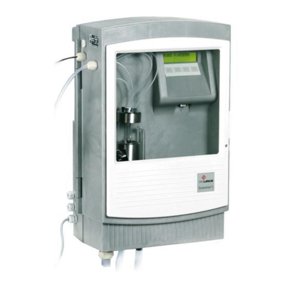
General Information Instrument design Figure 1 Control unit Sample storage vessel Pressure sensor line Overflow drain tube Sample storage vessel lid Display with keypad 10 Sample storage vessel drain tube Sample tube Sample removal for process 11 Connection tube from the probe instruments Fiber optic cable for Mains connection cable... - Page 10 General Information Figure 2 Sampling probe Connection tube Sampling vessel Air outlet Probe cover Valve cover Drain valve...
-
Page 11: Section 3 Installation
Section 3 Installation D A N G E R Only qualified experts may conduct the tasks described in this section. D A N G E R Select a suitable attachment point for the instrument. Plan out the mechanical mount·before positioning poles or drilling holes. Make sure the mount has a sufficient bearing capacity. -
Page 12: Mechanical Installation
Installation Mechanical installation Figure 3 Dimensions (in mm) Suspension points Wood screw, 5 x 40 (3×) Fixing point Nylon plug, 8 x 40 (3×) - Page 13 Installation Figure 4 Installation overview SIGMATAX 2 open loop control unit 4 Mounting attachment SIGMATAX 2 sampling probe Connection tube (10–30 m) Base Direction of flow Retaining clamp Mounting pipe, 2 m (78.7 in)
-
Page 14: Install The Sampling Probe
Installation 3.1.1 Install the sampling probe Installation with rim mounting LZX414.00.00000 Figure 5 Base and mounting attachment Express anchor Mounting attachment Base Cylinder-head screw, M8 × 40 (4×) - Page 15 Installation N O T I C E When carrying out an installation variant that deviates from this example, make sure that the connection tube from the sampling probe is guided vertically upward for at least 0.5 m (19.6 in). Installation using pole mount LZX414.00.00000 Figure 6 Sampling probe and mounting pipe Mounting pipe, 2 m (78.7 in)
-
Page 16: Second Mounting Point And Extension Pipe
Installation 3.1.2 Second mounting point and extension pipe Figure 7 Second mounting point LZX456 Mounting pipe, 2 m (78.7 in) Retaining clamp EPDM flat seal Cylinder-head screw, M5 × 20 (3×) - Page 17 Installation N O T I C E When carrying out an installation variant that deviates from this example, make sure that the connection tube from the sampling probe is guided vertically upward for at least 0.5 m (19.6 in). Figure 8 Installation with extension pipe.
-
Page 18: Install The Open Loop Control Unit
Installation 3.1.3 Install the open loop control unit N O T I C E Install the open loop control unit in a dry location out of direct sunlight. Make sure that an area of 5 cm is kept free around the entire instrument to enable air to circulate (distance from the wall of the building, cable channel etc.). - Page 19 Installation Figure 9 Open loop control unit and process instrument SIGMATAX 2 open loop control unit 5 Separate drain pipe for process Drain tube for process instrument instrument Fiber optic cable to the process SIGMATAX 2 connection tube 10 SIGMATAX 2 drain tubes...
-
Page 20: Prepare The Connection Tube
Installation 3.1.4 Prepare the connection tube D A N G E R The pipe trace heater in the connection tube is operated at 230 V. If any damage occurs to the tube casing, the entire system must be taken out of operation immediately. Figure 10 Connection tube Protective tube... -
Page 21: Connect The Connection Tube
Installation 3.1.5 Connect the connection tube Figure 11 Connections for connection tube and drain tubes Air hose (drain valve), Ø 3 mm Electrical connection cable for the Overflow drain tube (0.11 in) pipe trace heater Air hose, Ø 5 mm (0.19 in) Connection tube from the sampling Drain fitting probe... -
Page 22: Electrical Installation
Installation Electrical installation N O T I C E Protect the instrument from extreme temperatures from heaters, direct sunlight and other heat sources. WA R N I N G Electrical and fire hazards. Use only the supplied power cable. Only qualified experts may perform the tasks described in this section of the manual, while adhering to all locally valid safety regulations. - Page 23 Installation Figure 12 Terminal assignment Connection cable for pipe trace heater Connection terminals for heater (N, L = terminals 8 + 9 from the top) Fault indication contact (circuit diagram shows contact Connection terminal for earth conductor during a fault indication) Open 1/2, closed 2/3 N O T I C E Route the signal lines (1, 2, 3) separated from the power cable.
-
Page 24: Connect The Fiber Optic Cable
3.2.2 Connect the fiber optic cable Figure 13 Fiber optic cable connection Fiber optic cable for SIGMATAX 2 with PG screw Knurled-head screw for opening the front panel connection Blind plug for fiber optic cable PG screw connection Fiber optic cable connection... - Page 25 Installation Figure 14 Sample storage vessel Level indicator pipe Sample tube Ultrasound transducer O-ring Connection cable for ultrasound 10 Cross-head screw, M4 × 16 (2×) transducer Sample storage vessel cover with Pressure sensor line O-ring compression fittings Small sample pipe Sample tube...
- Page 26 Installation...
-
Page 27: Section 4 Start Up
Section 4 Start Up After the sampling probe and control unit have been fully installed and all lines have been connected (connection tube, sampling and drain tubes, fiber optic cables), the mains plug can be plugged in. If there is a risk of freezing, switch on the pipe trace heater! WA R N I N G The pipe trace heater in the connection tube is operated at 230 V. - Page 28 Start Up...
-
Page 29: Section 5 Operation
Section 5 Operation Operation All instrument functions are controlled by the software. The instrument is operated via menus using four keys that are located below the display. From operational mode, you can access the first menu level by pressing the function keys, F1 to F4, for 3 seconds. The functions of the keys in the individual menus may vary, and are therefore shown (abbreviated clearly) in the second row of the display (softkey function). -
Page 30: Menu Overview
Operation Menu overview Menu level 1 Menu level 2 Menu level 3 Description Language Option to select the language for the menus +SETTINGS HEATER Self-adjusting pipe trace heater — for parameterizing the instrument turn on if there is a risk of freezing! Time interval (6–60 minutes) between Interval 2 samples. -
Page 31: Important Instrument Settings
Operation Important instrument settings 5.3.1 Switch on the heater 1. Press one of the function keys, F1 to F4, for 3 seconds. 2. Open the +SETTINGS menu by pressing F2. 3. Press F4 to scroll to the [heating] menu item 4. -
Page 32: Access Service Mode
Operation 5.3.5 Access service mode 1. Press one of the function keys, F1 to F4, for 3 seconds. 2. Press F4 twice to scroll to the [+SERVICEMENU] menu. 3. Press F2 to open this menu. 4. When the [+INSPECTION] or [+FUNCTION TEST] menus are selected, the system automatically switches to service mode. -
Page 33: Section 6 Maintenance
Section 6 Maintenance The manufacturer recommends that an inspection contract be concluded. This contract extends the warranty period to 5 years and makes sure that all inspection and maintenance tasks are carried out by qualified experts. Maintenance tasks for users are limited to regular visual inspections and, if necessary, cleaning procedures. -
Page 34: Maintenance Tasks
Maintenance Maintenance tasks 6.1.1 After 1–4 weeks (as necessary) D A N G E R Potential dangers with contact with chemical/biological substances. Working with chemical samples, standards and reagents is linked with dangers. Make yourself familiar with the necessary safety procedures and the correct handling of the chemicals before the work and read and follow all relevant safety data sheets. -
Page 35: 1×/Month (Or As Necessary)
Maintenance 6.1.2 1×/month (or as necessary) D A N G E R Potential dangers with contact with chemical/biological substances. Working with chemical samples, standards and reagents is linked with dangers. Make yourself familiar with the necessary safety procedures and the correct handling of the chemicals before the work and read and follow all relevant safety data sheets. - Page 36 Maintenance...
-
Page 37: Section 7 Troubleshooting
Section 7 Troubleshooting As soon as a fault leads to an interruption in operation, SIGMATAX 2 immediately switches to service mode. Corresponding error messages are shown both on the SIGMATAX 2 display and on the displays of the connected process photometers. - Page 38 Troubleshooting...
-
Page 39: Section 8 Replacement Parts And Accessories
Section 8 Replacement parts and accessories Product contents Description Cat. No Control unit LXV215 10 m (393.7 in) connection tube + sampling probe LXV231 20 m (787.4 in) connection tube + sampling probe LXV232 30 m (1181.1 in) connection tube + sampling probe LXV282 Storage vessel LZX394... - Page 40 Replacement parts and accessories Replacement and wear parts Description Cat. No Probe line 10 m (393.7 in) LZX393 Probe line 20 m (787.4 in) LZX398 Probe line 30 m (1181.1 in) LZX411 Bottom overflow fitting LZX388 Complete ultrasound transducer LZX284...
-
Page 41: Section 9 Warranty And Liability
Section 9 Warranty and liability The manufacturer warrants that the product supplied is free of material and manufacturing defects and undertakes the obligation to repair or replace any defective parts at zero cost. The warranty period for instruments is 24 months. If a service contract is taken out within 6 months of purchase, the warranty period is extended to 60 months. - Page 42 Warranty and liability...
- Page 44 Fax (970) 669-2932 Fax +49 (0) 2 11 52 88-210 Tel. +41 22 594 6400 orders@hach.com info-de@hach.com Fax +41 22 594 6499 www.hach.com www.de.hach.com © Hach Company/Hach Lange GmbH, 2003, 2012, 2018 All rights reserved. Printed in Germany 05/2018, Edition 3...
Need help?
Do you have a question about the SIGMATAX 2 and is the answer not in the manual?
Questions and answers