Hach 2100Q Manual
- Basic user manual (344 pages) ,
- User instructions (72 pages) ,
- Service manual (67 pages)
Advertisement
Specifications
Specifications are subject to change without notice.
| Specification | Details |
| Power requirement | AC 100–240 V, 50/60 Hz to 9V/2A DC (with power or USB +Power module) 4 AA alkaline batteries Rechargeable NiMH (for use with USB+Power module) |
General Information
In no event will the manufacturer be liable for direct, indirect, special, incidental or consequential damages resulting from any defect or omission in this manual. The manufacturer reserves the right to make changes in this manual and the products it describes at any time, without notice or obligation. Revised editions are found on the manufacturer's website.
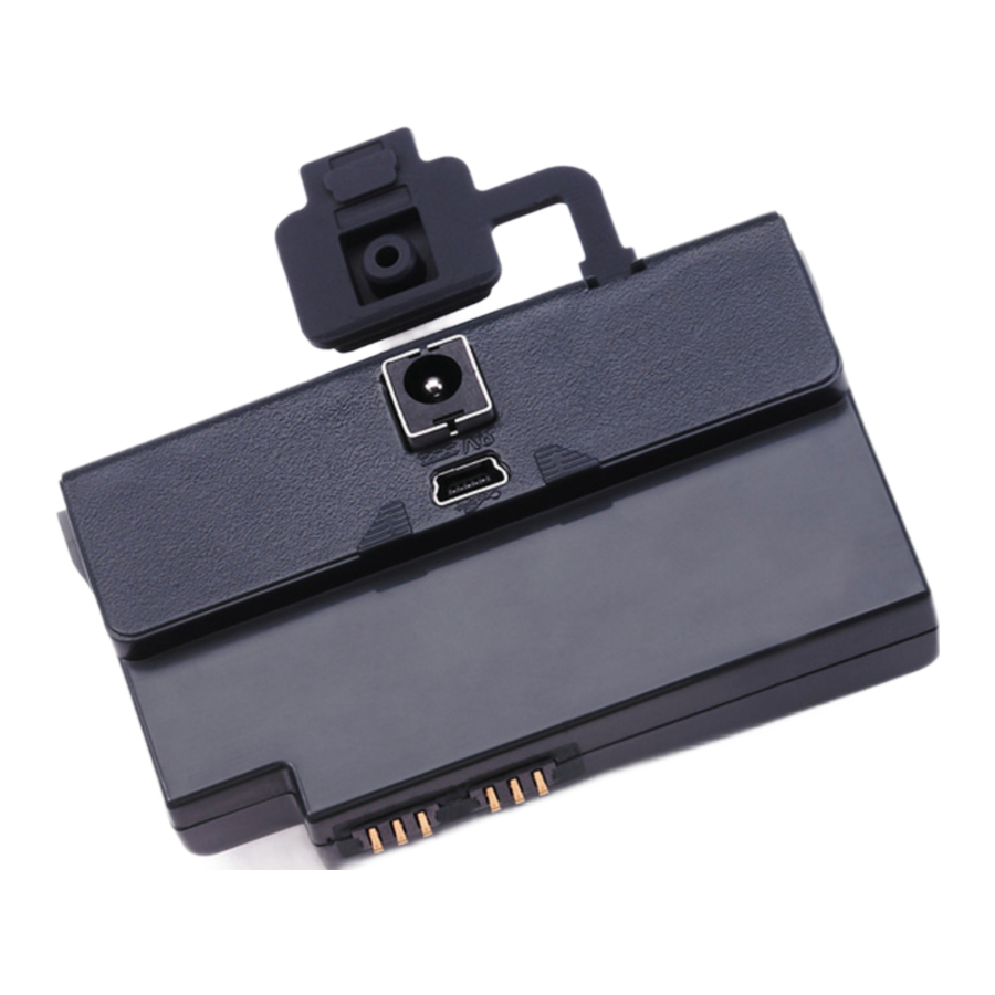
Product overview
There are two types of modules that can be used with 2100Q and the 2100Qis: the power module and the USB+Power module. The meter can be powered by an AC-DC power adaptor with both power modules. The USB+Power module is also used for communication with a PD-2 Citizen printer, USB-Barcode scanner and computer. The module firmware can be updated with a file downloaded from the computer.
Power module components
NOTICE
The manufacturer recommends to use only the supplied power supply (LZV803)

Refer to Figure 1 to make sure that all components have been received. If any of these items are missing or damaged, contact the manufacturer or a sales representative immediately.
|
|
USB+Power module components
NOTICE
The manufacturer recommends to use only the supplied power supply (LZV803).

Refer to Figure 2 to make sure that all components have been received. If any of these items are missing or damaged, contact the manufacturer or a sales representative immediately.
|
|
|
|
Installation
Install the battery

Potential fire hazard. Use only alkaline or nickel metal hydride batteries (NiMH) in the meter. Other battery types or incorrect installation can cause a fire. Never mix battery types in the meter.
NOTICE
The battery compartment is not waterproof. If the battery compartment becomes wet, remove and dry the batteries and thoroughly dry the interior of the compartment. Check the battery contacts for corrosion and clean them if necessary.
NOTICE
When using nickel metal hydride (NiMH) batteries, the battery icon will not indicate a full charge after freshly charged batteries have been inserted (NiMH batteries are 1.2 V versus 1.5 V for alkaline batteries). Even though the icon does not indicate complete charge, 2300 mAH NiMH batteries will achieve 90% of instrument operation lifetime (before recharge) versus new alkaline batteries.
NOTICE
To avoid potential damage to the meter from battery leakage, remove the meter batteries prior to extended periods of non-use.
The meter can be powered with AA alkaline or rechargeable NiMH batteries. To conserve battery life, the meter will power off after 10 minutes of inactivity. The backlight powers off after 30 seconds. Select a new time in the Power Management menu to change the power-off default times.
Note: Rechargeable batteries will only be recharged with the USB+Power module.
Refer to the Instrument User Manual for additional information about battery installation.
Power module and USB+Power module installation
Refer to the numbered step procedures for instructions on how to install the power module and USB+Power module.


Operation
Send data to the computer
Data that has been downloaded to the USB+Power module can be transferred and stored to a computer. The data will be formatted as an XML file.
- Push the DATA MANAGEMENT key.
- Select Send Data Log.
| Option | Description |
| Send Data | All data is sent to the USB+Power module |
| Filter Data | Data is filtered by: Data Type—All Logs, Reading Log, Calibration Log and Verify Cal Log Time Interval—All Logs, Last Reading, Current Day, Current Week and Current Month Sample ID—Off or Sample ID Operator ID—Off or Operator ID |
- Select Send Data to send all data to the USB+Power module.
- Select Filter Data. Make a choice of the data to transfer and push Exit. Select Send Data to send the selected data to the USB+Power module.
A progress bar will show the transfer status and shows "Transfer Complete" when the data is successfully sent to the USB+Power module.
- Remove the USB+Power module from the meter.
Note: Do not connect the USB+Power module to the computer when the module is still connected to the meter. - Plug the USB cable, type A, to the USB+Power module and connect the USB+Power module to the PC.
Note: The USB+Power module works like a USB storage device. Navigate through Windows Explorer to find the USB+power module. - Open the folder "datalog". Find the data file.
The file name will be formatted as: Year_Month_Day_Hour_Minute.xml. - Save the data file to a location on the computer.
- Open a spreadsheet program to view the data.
Print stored data
All data can be sent automatically to a printer. The PD-2 Citizen Printer is compatible with the meter and is FCC Part 15B, Class B compliant. Other printers may not be compatible.
Printer setup
Refer to the documentation supplied with the printer to select the USB interface.
Print data
- Turn off the meter. Install the USB+Power module to the meter and to AC power.
- Connect the printer to the USB+Power module with the USB cable supplied with the printer and the special USB cable adapter supplied with the module.
- Connect the printer to power and turn the printer on.
- Push the ON/OFF key to turn the meter on. The meter automatically detects when the printer is installed.
Note: After a reading is taken, the data is automatically transferred to the printer when the Auto-print data is selected. - Push the DATA MANAGEMENT key and select Send Data Log. Select one of the following options:
| Option | Description |
| Send Data | Data is sent directly to the printer. |
| Filter Data | Select specific data and then press Send Data. Data type—All Logs (Default setting), Reading Log, Calibration Log or Verify Cal Log Time Interval—All Logs (Default setting), Last Reading, Current day, Current week or Current Month Sample ID Operator ID Note: Sample ID and Operator ID are disabled when no ID was created. |
Update firmware
Locate the firmware upgrade file on the product website. Save the file from the website to the PC.
- Connect the USB+Power module to the PC.
- Copy the update file "UI_TP_TURB.blk" file to the USB+Power module.
- Unzip the file "Ing.zip and copy the folder "Ing" to the USB+Power module.
- Disconnect the USB+Power module from the PC.
- Plug the USB+Power module into the meter.
- Press and hold the POWER key for four seconds.
- The update process starts. The display shows "Updating meter to <firmware version>". After this update, the language update starts automatically. The display shows "Updating files..." and then shows "Update complete" when the update is done.
- Press DONE.
- Select the appropriate language.
- Press OK.
The meter is ready to use.
Connect the USB+Power module to a USB-Barcode scanner
If a USB-Barcode handset scanner is connected, Sample IDs and Operator IDs can also be scanned.
- Connect the USB-Barcode scanner cable to the adapter cable (USB A receptacle to USB B mini B plug).
- Connect the adapter cable to the USB+Power module.
- Push the POWER key to turn the meter on.
- Select between two options:
- Scan the appropriate barcode. A new sample ID is created and automatically stored with the next reading.
- Select DATA MANAGEMENT and then Sample ID or Operator ID. Select Create New ID and scan the appropriate barcode. The new ID is automatically stored.
Replacement parts and accessories
Product and Article numbers may vary for some selling regions. Contact the appropriate distributor or refer to the company website for contact information.
| Accessories | ||
| Description | Quantity | Item no. |
| USB+Power module (includes: universal power supply, USB cable (2x), documentation) | 1 | LZV813 |
| Power module (includes: universal power supply, documentation) | 1 | LZV804 |
| Printer, Citizen PD-24 USB printer, 120– 220 VAC | 1 | US: 2960100 EU: 5835900.00 |
| Printer paper for Citizen PD-24, thermal | 5/pkg | 5836000 |
| USB-Barcode Scanner (handset scanner) | 1 | LZV566 |
| Power supply, 110-240 VAC | 1 | LZV803 |
| Module cover | 1 | LZV824 |
| Connector cover, USB+Power module | 1 | LZV825 |
| Connector cover, power module | 1 | LZV826 |
| Standard USB Cable with Mini USB connector | 1 | LZV818 |
| Special USB Cable adapter | 1 | LZV819 |
Safety information
Please read this entire manual before unpacking, setting up or operating this equipment. Pay attention to all danger and caution statements. Failure to do so could result in serious injury to the operator or damage to the equipment.
Make sure that the protection provided by this equipment is not impaired, do not use or install this equipment in any manner other than that specified in this manual.
Use of hazard information

Indicates a potentially or imminently hazardous situation which, if not avoided, will result in death or serious injury.

Indicates a potentially or imminently hazardous situation which, if not avoided, could result in death or serious injury.

Indicates a potentially hazardous situation that may result in minor or moderate injury.
NOTICE
Indicates a situation which, if not avoided, may cause damage to the instrument. Information that requires special emphasis.
Precautionary labels
Read all labels and tags attached to the instrument. Personal injury or damage to the instrument could occur if not observed. A symbol, if noted on the instrument, will be included with a danger or caution statement in the manual.
 | This symbol, if noted on the instrument, references the instruction manual for operation and/or safety information. |
 | This symbol, when noted on a product enclosure or barrier, indicates that a risk of electrical shock and/or electrocution exists. |
Documents / ResourcesDownload manual
Here you can download full pdf version of manual, it may contain additional safety instructions, warranty information, FCC rules, etc.
Advertisement


Need help?
Do you have a question about the 2100Q and is the answer not in the manual?
Questions and answers