
Related Manuals for Hioki 3506-10


Summary of Contents for Hioki 3506-10
- Page 1 3506-10 Instruction Manual C METER Sept. 2018 Revised edition 2 3506B981-02 18-09H...
-
Page 3: Table Of Contents
Contents Contents Introduction.................1 Verifying Package Contents ............1 Safety Information ..............2 Operating Precautions..............4 Chapter 1 Overview ___________________________________ 7 Product Overview ............7 Features ...............7 Entire Workflow ............9 Names and Functions of Parts ........11 Chapter 2 Measurement Preparations___________________ 17 Preparation Flowchart ..........17 Checking the Power Voltage ........18 Connecting the Power Cord ........ - Page 4 Contents Chapter 4 Compensate for errors_______________________ 37 Open Circuit Compensation and Short Circuit Compensation ............37 Load Compensation ..........45 Offset Compensation ..........51 Self Calibration ............55 Set the Cable Length ..........58 Chapter 5 Judging measurement results ________________ 59 Comparator Function ..........
- Page 5 Contents 6.15 Printing Function ............115 6.15.1 Preparation Prior to Connecting the Printer ....115 6.15.2 Connection Procedure ..........118 6.15.3 Printing ................119 Chapter 7 EXT I/O __________________________________ 121 About the EXT I/O Connector ........121 Circuit Configuration and Connections of the EXT I/O Connector ..............123 About Input and Output Signals .......124 About Measurement Times ........127...
- Page 6 Contents 8.11 Creating Programs ..........247 8.11.1 Creation Procedure ............. 247 8.11.2 Sample Programs ............249 8.12 Troubleshooting the Interface ........251 8.13 Device Document Requirements ......253 Chapter 9 Specifications _____________________________ 257 Basic Specifications ..........257 Accuracy ..............261 Measurement Parameters and Arithmetic Expressions .............
-
Page 7: Introduction
Introduction Introduction Thank you for purchasing the HIOKI “Model 3506-10 C Meter.” To obtain maxi- mum performance from the unit, please read this manual first, and keep it handy for future reference. Verifying Package Contents When you receive the unit, inspect it carefully to ensure that no damage occurred during shipping. -
Page 8: Safety Information
Safety Information Safety Information This instrument is designed to comply with IEC 61010 Safety Standards, and has been thoroughly tested for safety prior to shipment. However, mishandling during use could result in injury or death, as well as damage to the instrument. Using the instrument in a way not described in this manual may negate the provided safety features. - Page 9 Safety Information Measurement Categories To ensure safe operation of measurement instruments, IEC 61010 establishes safety standards for various electrical environments, categorized as CAT II to CAT IV, and called measurement categories. These are defined as follows. CAT II: Primary electrical circuits in equipment connected to an AC electrical outlet by a power cord (portable tools, household appliances, etc.) CAT II covers directly measuring electrical outlet receptacles.
-
Page 10: Operating Precautions
• Before using the unit the first time, verify that it operates normally to ensure that the no damage occurred during storage or shipping. If you find any dam- age, contact your dealer or Hioki representative. • Before using the unit, make sure that the insulation on the probes and cables is undamaged and that no bare conductors are improperly exposed. - Page 11 • Do not allow the instrument to get wet, and do not take measurements with wet hands. This may cause an electric shock. • Never modify the unit. Only Hioki service engineers should disassem- ble or repair the unit. Failure to observe these precautions may result in fire, electric shock, or injury.
- Page 12 About the guarantee You should be aware that HIOKI cannot accept any responsibility directly or indi- rectly if the unit has been incorporated in some other system, or if it is resold to a third party.
-
Page 13: Chapter 1 Overview
Chapter 1 Overview 1.1 Product Overview The HIOKI Model 3506-10 C Meter are capacitance meters employing 1 kHz and 1 MHz frequencies to measure large-value multilayer ceramic capacitors with constant voltage at high speed and high accuracy. Primary applications include pass-fail judgment and ranking of capacitors on tape machines and sort- ers. - Page 14 1.2 Features Trigger-synchronous measurement capability (p. 103) The measurement signal can be input to the sample in sync with a trigger. Frequency shift function (p. 101) When using multiple devices, decreases measurement value fluctuation due to interference by shifting the measuring frequency of each device. Contact check function (p.
-
Page 15: Entire Workflow
1.3 Entire Workflow 1.3 Entire Workflow Measurement Chapter 2 "Measurement Preparations" (p. 17) Preparations 1. Check the power voltage. 2. Connect the power cord. 3. Connect the probes or fixture (option) to the measurement terminals. 4. Turn the power on. 5. - Page 16 Applied voltage monitoring (p. 100) is being produced. function Frequency shift Reduce the differences in measurement values caused by interference when using multiple 3506-10 units for mea- (p. 101) surement. Display Turns the LED display ON/ OFF. (p. 102) Trigger synchronous output...
-
Page 17: Names And Functions Of Parts
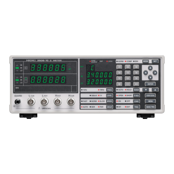
1.4 Names and Functions of Parts 1.4 Names and Functions of Parts Front SUB Display Displays the limit values of BIN and comparator. MAIN Display Comparator Evaluation Setting Condition Result Display Displays the measurement Display values of C and D ( or Q). Displays evaluation results in Comparator Mode. - Page 18 1.4 Names and Functions of Parts Operating Panel Keypad Measurement mode setting (p. 26) Used to enter numeric values. Comparator measure- ment function (p. 59) BIN measurement function (p. 74) Arrow keys Used to change settings and move to menu items or digits.
- Page 19 1.4 Names and Functions of Parts Back EXT I/O Connector RS-232C GP-IB Connector Connector Inputs external trigger signals and Connect an RS-232C Connect a GP-IB cable. outputs comparator result signals cable. and other signals. Supports con- Chapter 8 "Control- nection to a PLC (Programmable ling the Unit from a Logic Controller).
- Page 20 1.4 Names and Functions of Parts Menu display organization Displays menu screen (MAIN display area) Panel Load Panel Save Load Average Function Function Conditions Function “LoAd_A(C/h)” “SAVE” “Ld_tYP“ “AVErAG“ (p. 106) (p. 105) (p. 106) (p. 91) Trigger Synchro- Frequency shift Trigger Delay Cable length nous Function...
- Page 21 1.4 Names and Functions of Parts MAIN display area ERROR display When the 3506-10 detects a measurement abnormality, an error message is dis- played in the MAIN display area. When a measurement error occurs, the device's condition is displayed in order of priority rank in the MAIN display area.
- Page 22 It is possible that the device is being affected by incoming noise. output High Displayed when the A/D con- version is not carried out nor- The 3506-10 is broken. judgment, mally. Submit it for repairs. judgment Timeout It is possible that the device is being affected by incoming noise.
-
Page 23: Measurement Preparations
2.1 Preparation Flowchart Measurement Chapter 2 Preparations Be sure to read "Follow these precautions to ensure safe operation and to obtain the full benefits of the various functions." (p. 4) prior to setting up the unit. 2.1 Preparation Flowchart Check the power voltage. 2.2 "Checking the Power Voltage"... -
Page 24: Checking The Power Voltage
2.2 Checking the Power Voltage 2.2 Checking the Power Voltage • Before turning the unit on, make sure the supply voltage matches that indicated on the its power connector. Connection to an improper sup- ply voltage may damage the unit and present an electrical hazard. •... -
Page 25: Connecting The Power Cord
2.3 Connecting the Power Cord 2.3 Connecting the Power Cord To avoid electrical accidents and to maintain the safety specifications of this unit, connect the power cord provided only to a 3-contact (two-con- ductor + ground) outlet. • To avoid damaging the power cord, grasp the plug, not the cord, when unplugging it from the power outlet. -
Page 26: Connecting The Probes And Fixtures
Connector guides of the Measurement Align the grooves of the BNC connector with the Model 3506-10 measure- BNC Connector Grooves connector guides of the connector of the unit and ment terminal then insert the connector and rotate it clockwise until it locks into position. -
Page 27: Turning The Power On And Off
2.5 Turning the Power On and Off • Use Hioki fixtures (option), etc. Appendix 6 "Options" (p. A9) • This device is adjusted for 1.5D-2V coaxial cable use. Using other cable types may cause an increase in measurement errors. • If all four terminals are disconnected, a meaningless number may be dis- played on the unit. - Page 28 2.5 Turning the Power On and Off...
-
Page 29: Setting The Measurement Conditions
When the power is turned If the fan does not spin or the “3506-10” and ver- on, does the fan spin and do sion number indications are not displayed, the ... -
Page 30: Measurement Example
3.2 Measurement Example Example The 9263 SMD Test Fixture is used for the measurement of multi- layer ceramic capacitors.: Necessary tools • Model 3506-10 • Model 9263 SMD Test Fixture • Sample to be measured: Multilayer ceramic capacitor Measurement Conditions Connect the 9263 SMD Test Fixture (Option). - Page 31 3.2 Measurement Example Connect the sample to be measured to the 9263 SMD Test Fixture. For the connection method, refer to the instruction manual supplied with the fixture. Check the measurement results. Capacitance Dissipation Factor The voltage monitor and the current monitor can be checked on the SUB display.
-
Page 32: Setting The Measurement Conditions
3.3 Setting the Measurement Conditions 3.3 Setting the Measurement Conditions 3.3.1 Setting the Display Parameter The lower parameter (second parameter) of the MAIN display can either be set to D (dissipation factor) or Q (quality factor). Press The upper part of the MAIN display area displays the menu contents and the lower part displays the setting information. -
Page 33: Measurement Mode
3.3 Setting the Measurement Conditions 3.3.2 Measurement Mode Select a measurement mode. Press to change the mode. NORM COMP Mode: The selected item is indicated by the lit LED lamp. NORM Select this when using normal measurement mode. COMP Select this when using comparator measurement mode. 5.1 "Comparator Function"... -
Page 34: Measurement Signal Level
3.3 Setting the Measurement Conditions 3.3.4 Measurement Signal Level Set the measurement signal level. Set a signal level appropriate for the sample to be measured. Press to change the mode. 500 mV, 1 V Measurement signal level: The selected item is indicated by the lit LED lamp. •... -
Page 35: Equivalent Circuit Mode
3.3 Setting the Measurement Conditions 3.3.6 Equivalent Circuit Mode You may set an equivalent circuit mode (SER/ PAR). Automatic selection is also possible. "Equivalent Circuit Mode" (p. 30) Press to change the mode. AUTO Equivalent circuit mode: The selected item is indicated by the lit LED lamp. AUTO The series equivalent circuit mode or parallel equivalent circuit mode is automatically selected according to the measurement... - Page 36 3.3 Setting the Measurement Conditions Equivalent Circuit Mode This unit measures a current that flows through the sample and a voltage applied between terminals of the measurement sample to calculate and obtain imped- ance Z and phase angle . Static capacitance can be obtained using Z and values.
-
Page 37: Measurement Range
3.3 Setting the Measurement Conditions 3.3.7 Measurement Range Select a measurement range. Automatic selection is also possible. Press to change the mode. AUTO HOLD Measurement Range: The selected item is indicated by the lit LED lamp. AUTO The optimal measurement range is selected automatically. (Auto range) This is useful for the measurement of unknown samples. - Page 38 3.3 Setting the Measurement Conditions Guaranteed Accuracy Range 1 kHz 1 MHz Guaranteed accuracy Guaranteed accuracy Range Range range range 220 fF 0.000 fF to 330.000 fF 470 fF 68.000 fF to 680.000 fF 1 pF 0.15000 pF to 1.50000 pF 2.2 pF 0.33000 pF to 3.30000 pF 4.7 pF...
- Page 39 3.3 Setting the Measurement Conditions Auto Range 1 kHz 1 MHz Range Auto range Range Auto range 220 fF 0.000 fF to 330.000 fF 470 fF 220.000 fF to 680.000 fF 1 pF 0.47000 pF to 1.50000 pF 2.2 pF 1.00000 pF to 3.30000pF 4.7 pF 2.20000 pF to 6.80000 pF...
- Page 40 3.3 Setting the Measurement Conditions • If the measurement values displayed on the unit are outside of the guaran- teed accuracy range, the HOLD LED flashes. • For errors other than measurement value outside of range errors, refer to "MAIN display area ERROR display" (p. 15). •...
- Page 41 3.3 Setting the Measurement Conditions MAIN display Cause HOLD Setting: When input for current detection wave- form is out of the range. AUTO Setting: current detection waveform is out of the range. When measurement value is higher than upper value of Auto Range HOLD Setting: When input for voltage detection wave- form is out of the range.
-
Page 42: Trigger Signal
3.3 Setting the Measurement Conditions 3.3.8 Trigger Signal The internal trigger or the external trigger can be set. Press to change the mode. Trigger signal: Continuous measurement is performed while automati- (Internal trigger cally generating an internal trigger signal. mode) The INT LED lights up. -
Page 43: Compensate For Errors
4.1 Open Circuit Compensation and Short Circuit Compensation Compensate Chapter 4 for errors Open Circuit Compensation and Short Circuit Compensation Open circuit compensation and short circuit compensation enable you to reduce the effect of impedance remaining in parts such as the probe or fixture and improve measurement accuracy. - Page 44 4.1 Open Circuit Compensation and Short Circuit Compensation • The measurement accuracy values defined in the specifications are for when open circuit compensation and short circuit compensation are per- formed. • Be sure to perform compensation again after replacing the probe or fixture. You will be unable to obtain correct values if measurement is performed in the compensation state prior to replacement.
- Page 45 4.1 Open Circuit Compensation and Short Circuit Compensation Take the open circuit compensation and short circuit compensation values ________________________________ In normal measurement mode, press (Flash) (MAIN display area) Flash If you do not want to perform open circuit compensation, press to pro- ceed to configuring the short circuit compensation settings.
- Page 46 4.1 Open Circuit Compensation and Short Circuit Compensation Select "AdJuSt" and press Incorporate the open circuit compensation values. (ALL Compensation) (Flash) (MAIN display area) 1 kHz and 500 mV 1 kHz and 1 V of 1 MHz and 500 mV of compensation compensation of compensation...
- Page 47 4.1 Open Circuit Compensation and Short Circuit Compensation Compensation Error: If a compensation error occurs, a warning beep will sound and the state becomes as follows. The measurement frequency at which the error occurred can be ascertained from the underbar display. "MAIN display area ERROR display"...
- Page 48 4.1 Open Circuit Compensation and Short Circuit Compensation to select setting the short circuit menu item. Select "AdJuSt" and press Incorporate the short circuit compensation values. (ALL Compensation) (Light up) (Flash) (MAIN display area) 1 second displayed End of all 1 kHz end of compensation compensation...
- Page 49 4.1 Open Circuit Compensation and Short Circuit Compensation Setting Open Circuit and Short Circuit Compensation ON/ OFF ________ In normal measurement mode, press The state becomes as follows. (Flash) (Light up) (MAIN display area) Flash Pressing causes the display to change in the following manner. AdJuSt”...
- Page 50 4.1 Open Circuit Compensation and Short Circuit Compensation Press to confirm the open circuit compensation ON or OFF Open circuit compensation is set to OFF and the state becomes as follows. (Off) (Flash) The state of the open circuit compensation LED becomes as follows and the device enters the short circuit compensation setting mode.
-
Page 51: Load Compensation
With this function, when using multiple 3506-10 units, the measurement errors of individual 3506-10 units can be reduced and a single measurement value pro- duced. Alternately, the measurement values of the 3506-10 can be matched to those of a reference device. - Page 52 4.2 Load Compensation Take the load compensation rate._________________________________ In normal measurement mode, press The state becomes as follows. (Flash) (MAIN display area) to select setting the load circuit compensation menu item. Pressing causes the display to change in the following manner. “SEt”...
- Page 53 4.2 Load Compensation End of Compensation: If compensation is completed normally, a beep tone sounds once and the condi- tion becomes as follows. (Light up) (MAIN display area) 1 second light The unit returns to normal measurement mode. Compensation Error: If a compensation error occurs, a warning beep will sound and the state becomes as follows.
- Page 54 4.2 Load Compensation Setting Reference Value ________________________________________ In normal measurement mode, press The state becomes as follows. (Flash) (MAIN display area) to select setting the load circuit compensation menu item. Pressing causes the display to change in the following manner. “SEt”...
- Page 55 4.2 Load Compensation Use the numeric keypad or arrow keys to enter a reference value for C and then press (If you enter a number, each digit moves one place to the right.) Settable Range: -199999 to 999999 Move to the digit..Change the number ...
- Page 56 4.2 Load Compensation Setting Load Circuit Compensation ON/ OFF _______________________ In normal measurement mode, press The state becomes as follows. (Flash) (MAIN display area) Press to turn the load circuit compensation ON or OFF. Pressing causes the display to change in the following manner. “SEt”...
-
Page 57: Offset Compensation
4.3 Offset Compensation 4.3 Offset Compensation Compensates for discrepancy from the correct value by subtracting an optional input value from measurement results. This function can compensate for the dis- crepancy found when measuring a fixed sample, or enable interchangeability of measuring instruments when measuring a single sample. - Page 58 4.3 Offset Compensation Press to confirm offset compensation as enabled or dis- abled. When “on” is selected, the state becomes as follow. (MAIN display area) (SUB display area) Offset compensation value mantissa part Flash Offset compensation value index When “oFF” is selected, “Lo C” (Low C reject function setting screen) is shown in the upper part of the MAIN display area.
- Page 59 4.3 Offset Compensation Press to confirm the mantissa part of the C offset compen- sation value. The state becomes as follows. (SUB display area) Offset compensation value index Flash Input the C offset compensation value index with the arrow keys or the numeric keypad.
- Page 60 4.3 Offset Compensation Input the D (Q) offset compensation value with the arrow keys or the numeric keypad. (If you enter a number, each digit moves one place to the right.) Settable Range of D : -1.99999 to 1.99999 Settable Range of Q : -19999.9 to 19999.9 Move to the digit ..
-
Page 61: Self Calibration
4.4 Self Calibration 4.4 Self Calibration On the 3506-10 it is possible to reduce drift in the measurement value by carry- ing out self calibration. Self calibration numerically compensates for measuring circuit drift by measuring the internal standard signal to obtain a value that will compensate for any discrepancy between the current detection circuit and volt- age detection circuit. - Page 62 4.4 Self Calibration Performing Self Calibration ______________________________________ In normal measurement mode, press The upper part of the MAIN display area displays the menu contents and the lower part displays the setting information. (Refer to "Menu display organization" (p. 14) for menu order) This setting cannot be changed in comparator mode and BIN mode.
- Page 63 4.4 Self Calibration • In the following situations the standard signal is measured only the number of times set by the :CALIbration:AVERaging command and the arithmetical average (arithmetrical mean) is taken as the self calibration value regardless of the self calibration fuction setting. •...
-
Page 64: Set The Cable Length
4.5 Set the Cable Length 4.5 Set the Cable Length A length which matches that of the measurement cable can be set in order to compensate for error caused by extending the measurement cable. In normal measurement mode, press The upper part of the MAIN display area displays the menu contents and the lower part displays the setting information. -
Page 65: Judging Measurement Results
5.1 Comparator Function Judging measurement Chapter 5 results 5.1 Comparator Function This function enables you to set the upper limit and lower limit values for each of C and D (Q), and then indicates the judgment result with HI, IN, or LO in the comparator judgment result display area. - Page 66 5.1 Comparator Function • If the power is turned off while the unit is in comparator measurement mode, the unit will be in comparator measurement mode when the unit is turned back on again. • Set the upper limit and lower limit values of any parameter (C,D or Q) that does not require a comparator judgment to be made to OFF so that judg- ment will not be performed.
- Page 67 5.1 Comparator Function Press The judgment mode is confirmed. After confirmation, “bEEP_J” is displayed at the top of the MAIN display area. (Beep setting screen for judgment result) The judgment mode is not confirmed unless is pressed. Press The unit returns to normal measurement mode.
- Page 68 5.1 Comparator Function Setting the Upper Limit and Lower Limit Values for the Comparator Setting Workflow Normal measurement Switch to comparator measurement mode. (COMP Light up) mode The range is automatically set to HOLD. Comparator measurement Switch to the setting mode for the upper limit and lower limit values.
- Page 69 5.1 Comparator Function Measurement Make settings using the upper limit and lower limit values method 1 (count setting). (To make settings using a reference value and the upper limit and lower limit val- ues refer to "Measurement method 2" (p. 66)) Press to light up COMP and enter comparator measurement mode.
- Page 70 5.1 Comparator Function Press to confirm the C upper limit value. Enter C lower limit value setting mode. (SUB display area) Lower limit value Flash In the same way input the C lower limit value using the arrow keys or the numeric keypad. At time of shipment, it is set to ”...
- Page 71 5.1 Comparator Function Press to set the D (Q) upper limit value. Enter the D (Q) lower limit value setting mode. (SUB display area) (OFF) Lower Lower Flash limit Flash limit value value When the second parameter is Q When the second parameter is D In the same way input the D (Q) lower limit value using the arrow keys or the numeric keypad.
- Page 72 5.1 Comparator Function Measurement Make settings using a reference value and the upper limit and lower limit values ( setting and % setting) method 2 (To make settings using a reference value and the upper limit and lower limit val- ues refer to "Measurement method 1"...
- Page 73 5.1 Comparator Function Enter the C reference value using the arrow keys or the numeric keypad. (If you enter a number, each digit moves one place to the right.) % Settable Range : -199999 to 999999 (The setting cannot be set to "0") Move to the digit..
- Page 74 5.1 Comparator Function Enter the C upper limit value using the arrow keys or the numeric keypad. Settable Range • For the setting : OFF,-199999 to 999999 • For the % setting : OFF, -999.99 to 999.99 (When setting to "OFF"(p.71)) Move to the digit ..
- Page 75 5.1 Comparator Function Press to enter the D (Q) reference value setting mode. (SUB display area / % setting) Light up Light up Reference Reference Flash Flash value value When the second parameter is D When the second parameter is Q Enter the D (Q) reference value using the arrow keys or the numeric keypad.
- Page 76 5.1 Comparator Function Enter the D (Q) upper limit value using the arrow keys or the numeric keypad. Settable Range: OFF,-199999 to 199999 (When setting to "OFF"(p.71)) Move to the digit ..Change the number .. Setting a value lower than the lower limit value will not produce an error, but accurate judgment will not be possible.
- Page 77 5.1 Comparator Function • The upper limit and lower limit values for the count setting and the reference value for the % setting become display count values that are independent of the measurement conditions. If the measurement conditions differ, the absolute values that signify the count values change.
- Page 78 5.1 Comparator Function Comparator Measurement Results ________________________________ • The measurement conditions of comparator measurement mode use the mea- surement conditions of normal measurement. Set the comparator mode mea- surement conditions in normal measurement mode. 3.3 "Setting the Measurement Conditions" (p. 26) •...
- Page 79 5.1 Comparator Function Outputting Judg- • Output the judgment result for each of C and D (Q) (LO/IN/HI) and the AND results for both judgment results (only when both parameters are IN) from ment Results EXT.I/O. 7.1 "About the EXT I/O Connector" (p. 121) •...
-
Page 80: Bin Measurement Function
5.2 BIN Measurement Function 5.2 BIN Measurement Function This function enables you to set up to 13 categories of upper limit and lower limit values for C and one category of upper limit and lower limit values for D (Q), and indicates the judgment results in the BIN judgment result display area. - Page 81 5.2 BIN Measurement Function Setting Judgment Mode _________________________________________ Set the judgment mode before setting the BIN judgment conditions. (Select the count value setting, the deviation count ( ) setting, the deviation percent ( %) setting.) The judgment mode is common to comparator measurement and BIN measure- ment.
- Page 82 5.2 BIN Measurement Function Setting the Upper Limit and Lower Limit Values for the BIN Setting Workflow Normal measurement Switch to comparator measurement mode. (BIN Light up) mode (Twice) The range is automatically set to HOLD. Switch to the setting mode for the upper limit BIN measurement mode and lower limit values.
- Page 83 5.2 BIN Measurement Function Measurement Make settings using the upper limit and lower limit values method 1 (count setting). (To make settings using a reference value and the upper limit and lower limit val- ues refer to "Measurement method 2" (p. 81)) to switch to the BIN measurement mode.
- Page 84 5.2 BIN Measurement Function Press to confirm the BIN1 upper limit value. Enter the BIN1 lower limit value setting mode. (SUB display area) Light up Flash is not pressed, the BIN upper limit and lower limit values just entered will not be set. The previous BIN upper limit value and lower limit value will remain in effect.
- Page 85 5.2 BIN Measurement Function Press to enter the D (Q) upper limit value setting mode. (SUB display area) Light up Light up Upper Upper Flash Flash limit limit value value (OFF) When the second parameter is D When the second parameter is Q Enter the D (Q) upper limit value using the arrow keys or the numeric keypad.
- Page 86 5.2 BIN Measurement Function Press to confirm the D (Q) lower limit value. Press The unit switches to the BIN measurement mode. (Light up) "Performing BIN Measurement" (p. 88) • The upper limit and lower limit values for the count setting become display count values that are independent of the measurement conditions.
- Page 87 5.2 BIN Measurement Function Measurement Make settings using the reference value upper limit and lower limit values ( setting and % setting) method 2 (To make settings using a reference value and the upper limit and lower limit val- ues refer to "Measurement method 1"...
- Page 88 5.2 BIN Measurement Function Enter the C reference value using the arrow keys or the numeric keypad. (If you enter a number, each digit moves one place to the right.) Settable Range: -199999 to 999999 (The % setting cannot be set to 0.) Move to the digit ..
- Page 89 5.2 BIN Measurement Function Enter the BIN1 upper limit value using the arrow keys or the numeric keypad. Settable Range setting: OFF, 199999 to 999999 (When setting to "OFF"( p. 87)) • For the % setting: OFF, 999.99 to 999.99 •...
- Page 90 5.2 BIN Measurement Function Press to enter the BIN2 upper limit value setting mode. (SUB display area / % setting) BIN2 BIN2 Light up Light up Flash Flash Upper limit Upper limit value value Lower limit Lower limit value value ...
- Page 91 5.2 BIN Measurement Function Enter the D (Q) reference value using the arrow keys or the numeric keypad. Settable range: -199999 to 199999 Move to the digit..Change the number ... The reference value is set with the count value. At time of shipment it is set to ”0“.
- Page 92 5.2 BIN Measurement Function Press to confirm the D (Q) upper limit value. Enter the D (Q) lower limit value setting mode. (SUB display area / % setting) Light up Light up (OFF) Flash Lower Lower Flash limit limit value value When the second parameter is Q...
- Page 93 5.2 BIN Measurement Function Setting the Upper Limit and Lower Limit Values to OFF _______________ When entering the upper limit and lower limit values, use move left until the far left digit flashes and then press and hold for at least two seconds or use to move right until the far right digit flashes and then press and hold for at least two seconds.
- Page 94 5.2 BIN Measurement Function Performing BIN Measurement ____________________________________ • Starting with the lowest, checks to see if BIN numbers are within the set upper limit and lower limit value range and displays as a judgment result the first BIN number that is in range. •...
- Page 95 5.2 BIN Measurement Function Outputting Judg- • Output the judgment result for BIN (BIN1 to 13, OUT OF BINS, and D-NG) from EXT.I/O. ment Results 7.1 "About the EXT I/O Connector" (p. 121) • The BIN judgment results (IN/NG) can be differentiated by beep tones. 6.12 "Setting Beep Tones"...
- Page 96 5.2 BIN Measurement Function...
-
Page 97: Application Functions
6.1 Setting the Average Function Application Chapter 6 Functions 6.1 Setting the Average Function The average function performs an averaging process on the measurement val- ues. With the use of this function you can reduce measurement value fluctua- tions even in environments with a lot of noise. In normal measurement mode, press The upper part of the MAIN display area displays the menu contents and the lower part displays the setting information. - Page 98 6.1 Setting the Average Function Press to enable or disable the average function. When “oFF” is selected, the averaging process is not performed. “dELAY” (Trig- ger delay setting screen) will be shown in the MAIN display area. When “on” is selected, the number of measurements to be averaged will flash in the middle row of the SUB display area.
-
Page 99: Trigger Delay Setting
6.2 Trigger Delay Setting 6.2 Trigger Delay Setting This sets the delay time between when the trigger is detected and measuring begins. With the use of this function even if measurement is commenced imme- diately after connecting to a sample a reliable measurement value can be attained. - Page 100 6.2 Trigger Delay Setting When "on" is selected Enter the delay time using or the numeric keypad. (If you enter a number, each digit moves one place to the right.) Settable range : 0.000 to 9.999(s) Move to the digit ..Change the number Press to confirm the delay time setting.
-
Page 101: Using The Contact Check Function
6.3 Using the Contact Check Function 6.3 Using the Contact Check Function The contact check function contains the following two functions. Exclude abnormally low measurement results. (Low C reject func- • tion) (p. 96) If the C measurement value is abnormally small, it detects the measurement result as an error. -
Page 102: Setting The Low C Reject Function
6.3 Using the Contact Check Function Setting the Low C Reject Function 6.3.1 Press The upper part of the MAIN display area displays the menu contents and the lower part displays the setting information. (Refer to "Menu display organization" (p. 14) for menu order) to select the “Lo C”... - Page 103 6.3 Using the Contact Check Function When "on" is selected Enter the limit value using or the numeric keypad. (If you enter a number, each digit moves one place to the right.) Settable range : 0.000 to 10.000(%) Move to the digit..Change the number Press to confirm the limit value.
-
Page 104: Measurement Level Monitoring Function Settings
6.3 Using the Contact Check Function Measurement Level Monitoring 6.3.2 Function Settings Press The upper part of the MAIN display area displays the menu contents and the lower part displays the setting information. (Refer to "Menu display organization" (p. 14) for menu order) to select the “LEV.ChK”... - Page 105 6.3 Using the Contact Check Function Press to confirm the limit value. “JudGE”(Judgment mode setting screen) will be displayed in the MAIN display area. is not pressed, the measurement level monitoring function settings will not be saved. Press The unit returns to the measurement mode it was in prior to the menu items being displayed.
-
Page 106: Current Detection Circuit Monitoring Function
6.4 Current Detection Circuit Monitoring Function 6.4 Current Detection Circuit Monitoring Function If the measurement range is set too low for the object being measured or the object being measured is in a SHORT state, a current wave outside the permissi- ble range is generated. -
Page 107: Using The Frequency Shift Function
When using multiple 3506-10 in a single system, measurement value fluctua- tions may occur due to interference with the measurement signal between 3506- 10 units. By shifting the measurement frequency of each 3506-10, this function reduces measurement signal interference. • Frequency shift can be set to on when the measuring frequency is 1 MHz. -
Page 108: Setting The Display On/ Off
6.7 Setting the Display ON/ OFF 6.7 Setting the Display ON/ OFF It various circumstances, such as use with a production line, EXT I/O or inter- faces, displaying the measurement may be unnecessary. By using the display ON/ OFF setting, when the display is turned OFF the measurement time becomes faster and the device becomes more energy efficient. -
Page 109: Trigger Synchronous Output Function
6.8 Trigger Synchronous Output Function 6.8 Trigger Synchronous Output Function This function enables the measurement signal to be output after measurement is triggered and ensures that the signal is applied to the sample only during mea- surement. Thus reducing the generation of heat in the sample and decreasing electrode wear. -
Page 110: Disable Key Control (Keylock Function)
6.9 Disable Key Control (Keylock Function) 6.9 Disable Key Control (Keylock Function) If the keylock function is set, the keys on the front panel are disabled. This func- tion enables you to protect your setup. Setting the Keylock ____________________________________________ Press and hold for at least two seconds. -
Page 111: Save The Measurement Conditions (Panel Save Function)
6.10 Save the Measurement Conditions (Panel Save Function) 6.10 Save the Measurement Conditions (Panel Save Function) The current measurement conditions can be saved to internal memory. Up to 70 panels (70 sets) of measurement conditions can be saved. When the panel save function is used, the measurement mode and all of the measurement conditions are saved. -
Page 112: Load The Measurement Conditions (Panel Load Function)
6.11 Load the Measurement Conditions (Panel Load Function) 6.11 Load the Measurement Conditions (Panel Load Function) The saved measurement values and compensation values can be loaded from internal memory. First, set the load condition. There are the following three load conditions. •... - Page 113 6.11 Load the Measurement Conditions (Panel Load Function) to select a setting item. Pressing causes the display to change in the following manner. “ALL” Loads the measurement conditions (frequency, level, range, upper limit and lower limit values, etc.) and the open circuit, short circuit, and load compen- sation values.
- Page 114 6.11 Load the Measurement Conditions (Panel Load Function) Loading Panels ________________________________________________ Press The upper part of the MAIN display area displays the menu contents and the lower part displays the setting information. (Refer to "Menu display organization" (p. 14) for menu order) to select the “LoAd_A (“LoAd_C”, “LoAd_h”)”...
- Page 115 6.11 Load the Measurement Conditions (Panel Load Function) Use the numeric keypad or to select the panel number to load. The number is entered at the bottom of the MAIN display area. • Only saved numbers can be set. If a number that was not saved with the numeric keypad is set, the set number flashes and then changes to the nearest saved number after one second elapses.
-
Page 116: Setting Beep Tones
6.12 Setting Beep Tones 6.12 Setting Beep Tones The beep tone for judgment results and the key operations tone can be set. Setting the Beep Tone for Judgment Results of Comparator and BIN The following two possibilities can be chosen from. •... - Page 117 6.12 Setting Beep Tones Press If “oFF” is selected, the beep tone will not sound, regardless of the judgment result. The "bEEP_K"(Beep tone setting screen for key operations) indication is dis- played in the MAIN display area. If “on” is selected, the leftmost LED showing the beep tone setting details func- tion in the middle row of the SUB display area will flash.
-
Page 118: Setting The Beep Tone For Key Operations
6.12 Setting Beep Tones 6.12.2 Setting the Beep Tone for Key Operations Press The upper part of the MAIN display area displays the menu contents and the lower part displays the setting information. (Refer to "Menu display organization" (p. 14) for menu order) to select the "bEEP_K"... -
Page 119: Switching The Displayed Item (Sub Display)
6.13 Switching the displayed item (SUB display) 6.13 Switching the displayed item (SUB display) The item displayed in the SUB display area can be switched. • Range number (for normal measurement only) • Monitor value (Voltage between the terminals and the current flowing in the object being measured) •... -
Page 120: Performing A System Reset
If you execute a system reset, the measurement conditions are reset and the system is placed in the normal measurement mode. Appendix 7 "Initial Settings Table" (p. A11) The settings of the RS-232C interface in the 3506-10 unit are initialized to 9600 bps for the baud rate and CR+LF for the terminator. -
Page 121: Printing Function
6.15 Printing Function 6.15 Printing Function The optional 9442 Printer 9444 Connection Cable can be used to print measurement values. To avoid electric shock, turn off the power to all devices before plugging or unplugging any cables or peripherals. 6.15.1 Preparation Prior to Connecting the Printer Things to •... - Page 122 6.15 Printing Function Set the switches numbered 1 to 8 of DIP SW1 to either ON or OFF in accordance with the table below. ON LINE FEED Press the switch once to set a switch to ON and the switch once to set a switch to OFF.
- Page 123 6.15 Printing Function Switch No. Function (Press ON LINE) (Press FEED) Data bit length 8 bits 7 bits Use parity Parity setting Even Control flow H/W BUSY XON/XOFF Baud rate (Set to 19200 bps) After you finish configuring the switch numbered 8 of DIP SW3, press either the ON LINE switch or the FEED switch to complete the setup.
-
Page 124: Connection Procedure
Configure the printer and unit beforehand. 8.3.2 "Setting the Interface Communication Conditions" (p. 134) Procedure Turn off the power of the 3506-10 unit and the 9442 Printer . Connect the 9444 Connection Cable to the unit and the printer. 9442 Printer... -
Page 125: Printing
Set the RS-232C communication conditions on the PC as shown below. • Bits per second: 19200 • Data bits: 8 • Parity: None • Stop bits: 1 Flow control is automatically set to Hardware (RTS/CTS control) if the interface used with the 3506-10 unit is a printer. - Page 126 6.15 Printing Function...
-
Page 127: Chapter 7 Ext I/O
7.1 About the EXT I/O Connector Chapter 7 EXT I/O 7.1 About the EXT I/O Connector The EXT I/O connector includes the following functions. • Output signal for comparator result • Output signal for BIN result • Output end of measurement signal (EOM) •... - Page 128 7.1 About the EXT I/O Connector EXT I/O Connector Signal Lines __________________________________ All input and output signals other than the power signal are negative logic. TRIG If a negative logic signal is input in external trigger mode, a single measure- ment begins at the corresponding LOW level (100 s or more).
-
Page 129: Circuit Configuration And Connections Of The Ext I/O Connector
7.2 Circuit Configuration and Connections of the EXT I/O Connector Circuit Configuration and Connections of the EXT I/O Connector • The range of power voltages that can be connected to the external DC power supply EXT DCV and EXT COM terminals is 5 to 24 V DC. Do not apply a voltage that exceeds +24 V DC. -
Page 130: About Input And Output Signals
7.3 About Input and Output Signals 7.3 About Input and Output Signals Electrical Characteristics of Output Signals ________________________ The output signals are photocoupler open collector output. Inside the unit, a 3.3 k pull-up resistor is used to connect to the external DC power source (EXT DCV). - Page 131 7.3 About Input and Output Signals Approximate Symbol Description Time 100 s TRIG width (LOW) : Trigger signal minimum time 350 s From TRIG(LOW) to INDEX (HIGH) : Time from trigger to circuit response INDEX width (HIGH) : Minimum chuck time, switching chuck 0.6 ms with INDEX (LOW) is possible 2.0 ms...
- Page 132 7.3 About Input and Output Signals Self calibration ________________________________________________ When self calibration is set to MANUAL, a self calibration value is taken after measurement of the object being measured by making to be LOW during CALIB T9 (TRIG: from LOW to 300 s or greater). The self calibration value taken will be used for the following measurement.
-
Page 133: About Measurement Times
7.4 About Measurement Times 7.4 About Measurement Times Measurement times differ depending on the measurement conditions. Refer to the following values. • All of the values are reference values. Note that they may differ depending on the conditions of use. •... - Page 134 7.4 About Measurement Times Self Calibration The calculation speed of each self calibration value can be set using the :CALibration:SPEEd command. Time Self calculation time of one self calibration (ms) FAST (Initial setting) NORMAL SLOW 13.0 • In the following situations the standard signal is measured only the number of times set by the :CALIbration:AVERaging command and the arithmetical average (arithmetrical mean) is taken as the self calibration value regardless of the self calibration fuction setting.
-
Page 135: Controlling The Unit From A Pc
8.1 Outline and Features You can connect a PC to the unit via the GP-IB interface or RS-232C interface and control the unit from the PC. 3506-10 RS-232C cable or GP-IB cable • The buzzer tone can be switched on and off. -
Page 136: Specifications
5 to 9 V ON -9 to -5 V OFF If a PC is used to read data from the 3506-10 unit immediately after the power of the 3506-10 unit is turned on, undefined values may be read because of BA (TxD) being unstable. -
Page 137: Gp-Ib Specifications
8.2 Specifications Input Buffer Usage Amount Buffer Space CA(RTS) Send XOFF Send XON Control during When using hardware (RTS/CTS control): When CB(CTS) is confirmed to be OFF, the sending of data is halted. When it is Sending confirmed to be ON, the sending of data is resumed. When using software (XON/XOFF control): When XOFF is received, the sending of data is halted. -
Page 138: Connection And Setting Procedures
8.3 Connection and Setting Procedures 8.3 Connection and Setting Procedures 8.3.1 Connecting the RS-232C Cable / GP-IB Cable • Always turn both devices OFF when connecting and disconnecting an interface connector. Otherwise, an electric shock accident may occur. • To avoid damage to the unit, do not short-circuit the terminal and do not input voltage to the terminal. - Page 139 8.3 Connection and Setting Procedures Example: Connecting to a DOS/V PC Specification: D-sub 9-pin female and female connector, reverse connection 3506-10 Controller (DOS/V PC) BB (RxD) BB (RxD) BA (TxD) BA (TxD) CD (DTR) CD (DTR) AB (GND) AB (GND)
-
Page 140: Setting The Interface Communication Conditions
8.3 Connection and Setting Procedures 8.3.2 Setting the Interface Communication Conditions This section describes how to set the communication conditions for the interface used by the 3506-10 unit. A GP-IB interface, RS-232C interface, and 9442 Printer can be set. Setting Procedure for Communication Conditions___________________... - Page 141 8.3 Connection and Setting Procedures to select one of the above items. Pressing switches the display. “GPib” For using the GP-IB interface “rS” For using the RS-232C interface “Prnt” For using the 9442 Printer Press to set the interface type is confirmed. (SUB display area) Setting details flashes Selecting "Print"...
- Page 142 8.3 Connection and Setting Procedures to select a setting item. • If "GPib" was selected (for using the GP-IB interface): 1. Use the numeric keypad or to set an address (0 to 30) and then press to confirm the address. 2.
-
Page 143: Remote Function
8.4 Remote Function When a connection is established to the interface and communication begins, the 3506-10 unit enters remote mode (remote control state) and the RMT LED lights up. Connecting to the interface: 8.3 "Connection and Setting Procedures" (p. 132) Starting communication: 8.5 "Communication Procedure"... -
Page 144: Things To Know Before Beginning Communication
8.6 Things to Know before Beginning Communication 8.6 Things to Know before Beginning Communication 8.6.1 About Message Formats Program Messages_____________________________________________ Program messages can be divided into command messages and query mes- sages. • Command Message A command for controlling the unit such as an instruction to configure a set- ting or reset the settings of the device. - Page 145 8.6 Things to Know before Beginning Communication Command Syntax ______________________________________________ Command names are selected for functions to be executed in a language that is as easy as possible to understand, and command names can also be shortened. The unshortened form of a command name is known as the "long form" and the shortened form of a command name is know as the "short form".
- Page 146 • CR+LF • CR+LF • EOI • LF with EOI The 3506-10 unit analyzes a message after it has confirmed the message ter- minator. Depending on the interface setting, the following can be selected as terminators of response messages. • LF with EOI (initial state) •...
- Page 147 8.6 Things to Know before Beginning Communication Data Section___________________________________________________ A data section indicates the content of a command. In the unit, character data and decimal numeric data are used for data sections, and use differs depending on the command. (1) Character Data Character data begins with an alphanumeric character and consists of alpha- betic characters and numbers.
- Page 148 A colon does not need to be added to the beginning of simple and compound command headers. However, Hioki recommends adding a colon to the begin- ning of these headers to prevent them from being mixed up with headers that...
-
Page 149: About The Output Queue And Input Buffer
8.6 Things to Know before Beginning Communication 8.6.2 About the Output Queue and Input Buffer Output Queue _________________________________________________ The output queue is the area in the unit where response messages are stored. Stored response messages are cleared once they are read by the controller of the PC. -
Page 150: About The Status Byte Register
8.6 Things to Know before Beginning Communication 8.6.3 About the Status Byte Register RS-232 reads the status bytes to find out the status of the unit. The unit adopts the IEEE488.2 defined status model for parts related to the serial polling performed by the service request function. - Page 151 8.6 Things to Know before Beginning Communication Status Byte Register (STB)_______________________________________ A status byte register is an 8-bit register output from the unit to the controller dur- ing serial polling. If even one of the status byte register bits enabled by the ser- vice request enable register changes from "0"...
-
Page 152: About Event Registers
8.6 Things to Know before Beginning Communication 8.6.4 About Event Registers Standard Event Status Register (SESR) ____________________________ A standard event status register is an 8-bit register. If even one of the standard status byte register bits enabled by the standard event status enable register becomes “1,”... - Page 153 8.6 Things to Know before Beginning Communication Standard Event Status Enable Register (SESER) ____________________ When the standard event status enable register is used to set each of the bits to "1" the corresponding bits are enabled in the standard event status register. Standard Event Status Register (SESR) and Standard Event Status Enable Reg- ister (SESER) bit6...
- Page 154 8.6 Things to Know before Beginning Communication Event Status Register 0 (ESR0) Bit 7 Non-guaranteed accuracy bit Bit 6 Applied voltage abnormality Bit 5 Current detection abnormality Bit 4 First parameter over range bit Bit 3 First parameter under range bit Bit 2 Data incorporation end bit Bit 1...
- Page 155 8.6 Things to Know before Beginning Communication Event Status Register 0 (ESR0), 1 (ESR1), 2 (ESR2), and 3 (ESR3) and Event Status Enable Register 0 (ESER0), 1 (ESER1), 2 (ESER2), and 3 (ESER3) Status Byte Register (STB) bit4 bit3 bit2 bit1 bit0 Event Status Register 0 (ESR0)
- Page 156 8.6 Things to Know before Beginning Communication Reading and Writing of Each Register _____________________________ Register Read Write Status Byte Register STB? Service Request Enable Register SRE? Standard Event Status Register ESR? Standard Event Status Enable Register ESE? Event Status Register 0 :ESR0? Event Status Enable Register 0...
-
Page 157: Message List
8.7 Message List 8.7 Message List 8.7.1 Common Commands Reference Command Data Section Explanation Error Page *CLS Clearing of the event register *1, 3 *ESE Numeric values 0 Setting of the standard event status enable register *3, 5 to 255 (NR1) *ESE? Query of standard event status enable register *1, 2, 3... -
Page 158: Unique Commands
8.7 Message List 8.7.2 Unique Commands Refer- Command Data Section Explanation ence Error Page Average Function :AVERageing Setting of the number of measurements to av- *2, 3 1 to 256 (NR1) erage :AVERaging? Query of the number of measurements to av- *1, 2 erage :AVERageing:STATe... - Page 159 8.7 Message List Refer- Command Data Section Explanation Error ence Page :BIN:FLIMit:CDEViation <BIN Number>, Setting of upper limit and lower limit values of *2, 3 <Lower Limit Value>, first parameter for BIN function in deviation <Upper Limit Value> count mode <BIN Number>...
- Page 160 8.7 Message List Refer- Command Data Section Explanation ence Error Page :BIN:SLIMit:CDEViation <Lower Limit Value>, Setting of upper limit and lower limit values of *2, 3 <Upper Limit Value> second parameter for BIN function in devia- <Lower Limit Value>, tion count mode <Upper Limit Value>...
- Page 161 8.7 Message List Refer- Command Data Section Explanation Error ence Page Cable Length :CALibration:CABLe Setting of cable length *2,3 0, 1, 2 (NR1) :CALibration:CABLe? Query of cable length *1, 2 Equivalent Circuit :CIRCuit Setting of equivalent circuit mode *2,3 SERial/ PARallel :CIRCuit? Query of equivalent circuit mode *1, 2...
- Page 162 8.7 Message List Refer- Command Data Section Explanation ence Error Page :COMParator:FLIMit <Reference Value>, Setting of reference value and upper limit and *2, 3 <Lower Limit Value>, lower limit values of first parameter for com- :PDEViation <Upper Limit Value> parator function in deviation percent mode <Reference Value>...
- Page 163 8.7 Message List Refer- Command Data Section Explanation Error ence Page Open Circuit and Short Circuit Compensation :CORRection:OPEN Setting of open circuit compensation function *2, 3 ALL/ ON/ OFF/ RETurn :CORRection:OPEN? Query of open circuit compensation function *1, 2 :CORRection:OPEN:DATA <compensation values Setting of open circuit compensation values *1, 2...
- Page 164 8.7 Message List Refer- Command Data Section Explanation ence Error Page :CORRection:LOAD? Query of load compensation function *1, 2 :CORRection:LOAD:DATA <compensation value Setting of load compensation values *1, 2 1>,<compensation val- ue 2> Differs depending on for- warding format :CORRection:LOAD:DATA? Query of load compensation values *1, 2 :CORRection:LOAD:DATA...
- Page 165 8.7 Message List Refer- Command Data Section Explanation Error ence Page Display Function :DISPlay ON/ OFF Setting of display *2, 3 :DISPlay? Query of display *1, 2 Confirmation of Communication Error Query of RS-232C error *1,2,6 :ERRor? Event Registers :ESE0 Numeric Value from 0 to Setting of event status enable register 0 *2, 3...
- Page 166 8.7 Message List Refer- Command Data Section Explanation ence Error Page Communication Handshake OFF/ X /HARDware Setting of RS-232C communication hand- *2,3,6 :HANDshake /BOTH shake Query of RS-232C communication hand- *1,2,6 :HANDshake? shake Header :HEADer ON/ OFF Setting of header for response messages *2, 3 :HEADer? Query of header for response messages...
- Page 167 8.7 Message List Refer- Command Data Section Explanation Error ence Page Measurement Signal Level :LEVel Setting of measurement signal level *2, 3 1/ 0.5 (NR2) :LEVel? Query of measurement signal level *1, 2 Detected Level Monitoring Function :LEVel:CHECk Setting of detected level monitoring function *2, 3 ON/ OFF :LEVel:CHECk?
- Page 168 8.7 Message List Refer- Command Data Section Explanation ence Error Page :MEMory:CONTrol? ON/ OFF query of measurement value mem- *1, 2 ory function :MEMory:POINts 1 to 1000 Setting of measurement value memory size *2, 3 :MEMory:POINts? Query of measurement value memory size *1, 2 Monitor :MONItor?
- Page 169 8.7 Message List Refer- Command Data Section Explanation Error ence Page :SPEEd FAST/ NORMal/ SLOW Setting of measurement speed *2, 3 :SPEEd? Query of measurement speed *1, 2 Trigger Synchronous Output Function :SSOurce ON/ OFF Setting of trigger synchronous output function *2, 3 :SSOurce? Query of trigger synchronous output function *1, 2 :SSOurce:WAIT...
- Page 170 8.7 Message List Refer- Command Data Section Explanation ence Error Page :VCHeck? Query of applied voltage monitoring function *1, 2 :VCHeck:LIMit 0.01 to 100.00 Setting of applied voltage monitoring function *2, 3 limit value :VCHeck:LIMit? Query of applied voltage monitoring function *1, 2 limit value Error Explanations (An error is generated when a message is executed in the following cases)
-
Page 171: Ability To Use Commands By State
8.8 Ability to Use Commands by State 8.8 Ability to Use Commands by State The ability to use commands depends on the state of the unit; for example, whether the unit is in a measurement mode or performing compensation. Refer to the following table. - Page 172 8.8 Ability to Use Commands by State Yes: Available : Only for commands available (Key unavailable) No: Unavailable Normal Comparator Performing Reference Command Name Measurement Measurement Measurement Compensation Page Mode Mode Mode :BIN:FLIMit:COUNt :BIN:FLIMit:COUNt? :BIN:FLIMit:CDEViation :BIN:FLIMit:CDEViation? :BIN:FLIMit:CREFerence :BIN:FLIMit:CREFerence? :BIN:FLIMit:PDEViation :BIN:FLIMit:PDEViation? :BIN:FLIMit:PREFerence :BIN:FLIMit:PREFerence? :BIN:SLIMit:COUNt...
- Page 173 8.8 Ability to Use Commands by State Yes: Available : Only for commands available (Key unavailable) No: Unavailable Normal Comparator Performing Reference Command Name Measurement Measurement Measurement Compensation Page Mode Mode Mode :COMParator:FLIMit:CDEViation? :COMParator:FLIMit:PDEViation :COMParator:FLIMit:PDEViation? :COMParator:SLIMit:COUNt :COMParator:SLIMit:COUNt? :COMParator:SLIMit:CDEViation :COMParator:SLIMit:CDEViation? :COMParator:SLIMit:PDEViation :COMParator:SLIMit:PDEViation? ...
- Page 174 8.8 Ability to Use Commands by State Yes: Available : Only for commands available (Key unavailable) No: Unavailable Normal Comparator Performing Reference Command Name Measurement Measurement Measurement Compensation Page Mode Mode Mode :DISPlay :DISPlay? :ERRor? :ESE0 :ESE0? :ESE1 :ESE1? :ESE2 :ESE2? :ESE3 :ESE3?
- Page 175 8.8 Ability to Use Commands by State Yes: Available : Only for commands available (Key unavailable) No: Unavailable Normal Comparator Performing Reference Command Name Measurement Measurement Measurement Compensation Page Mode Mode Mode :LOAD:TYPE? :MEASure? :MEASure:VALid :MEASure:VALid? :MEMory? :MEMory:CLEar :MEMory:COUNt? :MEMory:CONTrol :MEMory:CONTrol? :MEMory:POINts :MEMory:POINts?
- Page 176 8.8 Ability to Use Commands by State Yes: Available : Only for commands available (Key unavailable) No: Unavailable Normal Comparator Performing Reference Command Name Measurement Measurement Measurement Compensation Page Mode Mode Mode :VCHeck? :VCHeck:LIMit :VCHeck:LIMit?
-
Page 177: Message Reference
Sets the measurement signal level to 500 This explanation is normally for when HEADER ON. Query :LEVEL? (Except for HEADER com- :LEVEL 0.5 (when HEADER ON) mand.) (when HEADER OFF) The measurement signal level is set to 500 Command/query (message) 3506-10 Response (message) -
Page 178: Common Commands
(1) System Data Commands Query of Device ID (Identification Code) Syntax Query IDN? Response <Maker Name>,< Model Name>,0,<Software Version> Example HIOKI,3506-10,0,V1.00 (2) Internal Operation Commands Initialization of Device Syntax Command Explanation Initializes the unit. Appendix 7 "Initial Settings Table" (p. A11) - Page 179 8.9 Message Reference (3) Synchronization Commands Setting of OPC of SESR after All Executed Operations End Syntax Command Explanation Sets the OPC (bit 0) of SESR (standard event status register) when processing ends for sent commands prior to the *OPC command. Example A;B;*OPC;C Sets OPC of SESR after processing ends for commands A and B.
- Page 180 8.9 Message Reference (4) Status and Event Control Commands Clearing of Status Byte Register and Related Queues (Except Output Queue) Syntax Command Explanation Clears the content of the event registers (SESR, ESR0, ESR1, ESR2, ESR3). Note The output queue is not affected The output queue and the MAV (bit 4) of each type of enable register status byte are not affected.
- Page 181 8.9 Message Reference Reading and Clearing of Standard Event Status Register (SESR) Syntax Query ESR? Response <Numeric Value> <Numeric Value> = 0 to 255 (NR1) Explanation Returns the SESR content as an NR1 numeric value from 0 to 255, and then clears that content.
- Page 182 8.9 Message Reference Reading of Status Byte Register Syntax Query STB? Response <Numeric Value> <Numeric Value> = 0 to 255 (NR1) Explanation Returns the STB setting content as a NR1 numeric value from 0 to 127. No header is added to the response message. bit 7 bit 6 bit 5...
-
Page 183: Unique Commands
8.9 Message Reference 8.9.2 Unique Commands Setting and Query of the number of measurements to Average Syntax Command :AVERaging <Numeric Value> Query :AVERaging? <Numeric Value> = 1 to 256 (NR1) Response Explanation Command Set the number of measurements to average for the average mea- surement value. - Page 184 8.9 Message Reference Setting and Query of Comparator and BIN Judgment Beep Tone Setting Syntax Command :BEEPer:JUDGment <Character> Query :BEEPer:JUDGment? Response <Character> = IN/ NG/ OFF : Set so that the beep tone plays when the value is within the range : Set so that the beep tone plays when the value is outside the range...
- Page 185 8.9 Message Reference Setting and Query of ON/ OFF Setting of BIN Measurement Syntax Command :BIN <ON/ OFF> :BIN? Query <ON/ OFF> Response : Starts BIN measurement. OFF : Ends BIN measurement. Explanation Command Sets the BIN measurement function to ON/ OFF. If the ":BIN ON"...
- Page 186 8.9 Message Reference Setting and Query of SUB Display Indication During BIN Measurement Syntax :BIN:DISPlay Command <BIN Number/ Characters> :BIN:DISPlay? Query <BIN Number/ Characters> = 1 to 13(NR1)/ SECond/ CREFerence/ Response SREFerence/ OFF BIN Number : Sets the upper limit and lower limit values of the BIN number to be displayed in the SUB display area.
- Page 187 8.9 Message Reference Setting and Query of Upper Limit and Lower Limit Values of First Parame- ter for BIN Function in Count Value Mode Syntax Command :BIN:FLIMit:COUNt <BIN Number>,<Lower Limit Value>,<Upper Limit Value> Query :BIN:FLIMit:COUNt? <BIN Number> Response <BIN Number>,<Lower Limit Value>,<Upper Limit Value> <BIN Number>...
- Page 188 8.9 Message Reference Setting and Query of Upper Limit and Lower Limit Values of First Parame- ter for BIN Function in Deviation Count Mode Syntax Command :BIN:FLIMit:CDEViation <BIN Number>,<Lower Limit Value>,<Upper Limit Value> Query :BIN:FLIMit:CDEViation? <BIN Number> Response <BIN Number>,<Lower Limit Value>,<Upper Limit Value> <BIN Number>...
- Page 189 8.9 Message Reference Setting and Query of Reference Value of First Parameter for BIN Function in Deviation Count Mode Syntax Command :BIN:FLIMit:CREFerence <Reference Value> Query :BIN:FLIMit:CREFerence? <BIN Number> <Reference Value> = Numeric Value from -199999 to 999999 (NR1) Response Explanation Command Sets the reference value of the first parameter in deviation count mode.
- Page 190 8.9 Message Reference Setting and Query of Upper Limit and Lower Limit Values of First Parame- ter for BIN Function in Deviation Percent Mode Syntax Command :BIN:FLIMit:PDEViation <BIN Number>,<Lower Limit Value>,<Upper Limit Value> Query :BIN:FLIMit:PDEViation? <BIN Number> Response <BIN Number>,<Lower Limit Value>,<Upper Limit Value> <BIN Number>...
- Page 191 8.9 Message Reference Setting and Query of Reference Value of First Parameter for BIN Function in Deviation Percent Mode Syntax Command :BIN:FLIMit:PREFerence <Reference Value> Query :BIN:FLIMit:PREFerence? <Reference Value> = Numeric Value from -199999 to 999999 Response (excluding 0) (NR1) Explanation Command Sets the reference value of the first parameter in deviation percent mode.
- Page 192 8.9 Message Reference Setting and Query of Upper Limit and Lower Limit Values of Second Parameter for BIN Function in Count Value Mode Syntax Command :BIN:SLIMit:COUNt <Lower Limit Value>,<Upper Limit Value> Query :BIN:SLIMit:COUNt? <Lower Limit Value>,<Upper Limit Value> Response <Lower Limit Value> = OFF/ Numeric Value from -199999 to 199999 (NR1) <Upper Limit Value>...
- Page 193 8.9 Message Reference Setting and Query of Upper Limit and Lower Limit Value of Second Parame- ter for BIN Function in Deviation Count Mode Syntax Command :BIN:SLIMit:CDEViation <Lower Limit Value>,<Upper Limit Value> :BIN:SLIMit:CDEViation? <Lower Limit Value>,<Upper Limit Value> Query <Lower Limit Value> = OFF/ Numeric Value from -199999 to 199999 Response (NR1)
- Page 194 8.9 Message Reference Setting and Query of Upper Limit and Lower Limit Values of Second Parameter for BIN Function in Deviation Percent Mode Syntax Command :BIN:SLIMit:PDEViation <Lower Limit Value>,<Upper Limit Value> :BIN:SLIMit:PDEViation? <Lower Limit Value>,<Upper Limit Value> Query <Lower Limit Value> = OFF/ Numeric Value from -199999 to 199999 Response (NR1)
- Page 195 8.9 Message Reference Setting and Query of Reference Value of Second Parameter for BIN Function in Deviation Percent Mode Syntax Command :BIN:SLIMit:PREFerence <Reference Value> Query :BIN:SLIMit:PREFerence? <Reference Value> = Numeric Value from -199999 to 199999 (NR1) Response Explanation Command Sets the reference value of the second parameter in deviation percent mode.
- Page 196 8.9 Message Reference Calculates the Self Calibration Value Multiple Times Syntax Command :CALibration:ADJust Explanation Command When moving average processing is enacted the buffer of the saved self calibration value is erased and self calibration is performed. Example Command :CALibration:ADJust Measures the standard signal and takes the arithmetic average (arith- metic mean) from the number of measurements set by :CALibra- tion:AVERaging and produces an adjusted value, regardless of the self calibration function setting.
- Page 197 8.9 Message Reference Setting and Query of Number of Times to Average During Self Calibration Syntax Command :CALibration:AVERaging <Numeric values> Query :CALibration:AVERaging? Response <Numeric values> = 1 to 256 (NR1) Explanation Command Set the number of times to average during self calibration. Query Returns the number of times to average during self calibration as a NR1 numerical value.
- Page 198 8.9 Message Reference Setting and Query of Self Calibration Measurement Speed Syntax Command :CALibration:SPEEd <Character> Query :CALibration:SPEEd? Response <Character> = FAST/ NORMal/ SLOW Explanation Command Sets the measurement speed during self calibration. Query Returns the measurement speed during self calibration as characters. Example Command :CALibration:SPEEd NORMal...
- Page 199 8.9 Message Reference Automatic Setting and Query of Equivalent Circuit Syntax :CIRCuit:AUTO Command <ON/ OFF> Query :CIRCuit:AUTO? Response <ON/ OFF> : Switching is performed automatically. OFF : Switching is not performed automatically. Explanation Command Sets equivalent circuit mode to be switched automatically. Query Returns ON or OFF for the automatic setting of equivalent circuit mode.
- Page 200 8.9 Message Reference Setting and Query of SUB Display Indication During Comparator Measurement Syntax Command :COMParator:DISPlay <Character> Query :COMParator:DISPlay? Response <Character> = C/ SECond/ CREFerence/ SREFerence/ OFF : Sets the upper limit and lower limit values of C to be displayed in the SUB display area.
- Page 201 8.9 Message Reference Setting and Query of Upper Limit and Lower Limit Values of First Parame- ter for Comparator Function in Count Value Mode Syntax Command :COMParator:FLIMit:COUNt <Lower Limit Value>,<Upper Limit Value> :COMParator:FLIMit:COUNt? Query <Lower Limit Value>,<Upper Limit Value> Response <Lower Limit Value>...
- Page 202 8.9 Message Reference Setting and Query of Reference Value and Upper Limit and Lower Limit Values of First Parameter for BIN Function in Deviation Count Mode Syntax Command :COMParator:FLIMit:CDEViation <Reference Value>, <Lower Limit Value>,<Upper Limit Value> :COMParator:FLIMit:CDEViation? Query <Reference Value>, <Lower Limit Value>,<Upper Limit Value> Response <Reference Value>...
- Page 203 8.9 Message Reference Setting and Query of Reference Value and Upper Limit and Lower Limit Values of First Parameter for Comparator Function in Deviation Percent Mode Syntax Command :COMParator:FLIMit:PDEViation <Reference Value>, <Lower Limit Value>,<Upper Limit Value> :COMParator:FLIMit:PDEViation? Query <Reference Value>,<Lower Limit Value>,<Upper Limit Value> Response <Reference Value>...
- Page 204 8.9 Message Reference Setting and Query of Upper Limit and Lower Limit Values of Second Parameter for Comparator Function in Count Value Mode Syntax Command :COMParator:SLIMit:COUNt <Lower Limit Value>,<Upper Limit Value> :COMParator:SLIMit:COUNt? Query <Lower Limit Value>,<Upper Limit Value> Response <Lower Limit Value> = OFF/ Numeric Value from -199999 to 199999 (NR1) <Upper Limit Value>...
- Page 205 8.9 Message Reference Setting and Query of Reference Value and Upper Limit and Lower Limit Values of Second Parameter for Comparator Function in Deviation Count Mode Syntax Command :COMParator:SLIMit:CDEViation <Reference Value>, <Lower Limit Value>,<Upper Limit Value> :COMParator:SLIMit:CDEViation? Query <Reference Value>, <Lower Limit Value>,<Upper Limit Value> Response <Reference Value>...
- Page 206 8.9 Message Reference Setting and Query of Reference Value and Upper Limit and Lower Limit Values of Second Parameter for Comparator Function in Deviation Percent Mode Syntax Command :COMParator:SLIMit:PDEViation <Reference Value>, <Lower Limit Value>,<Upper Limit Value> :COMParator:SLIMit:PDEViation? Query <Reference Value>,<Lower Limit Value>,<Upper Limit Value> Response <Reference Value>...
- Page 207 8.9 Message Reference Setting and Query of Open Circuit Compensation Function Syntax :CORRection:OPEN Command <Character> <Character> ALL/ ON/ OFF/ RETurn :CORRection:OPEN? Query <Character> = ALL/ ON/ SPOT/ OFF Explanation Command Sets the open circuit compensation function. : Begins taking open compensation data for all measurement conditions (frequency, level), and enables the compensation function.
- Page 208 8.9 Message Reference Setting and Query of Open Compensation Values Syntax Command :CORRection:OPEN:DATA <Compensation values 1> <Com- pensation values 2> :CORRection:OPEN:DATA? Query <Compensation values 1> <Compensation values 2> Response <Compensation values 1> = -99.9999E9 to 99.9999E9 (NR3) <Compensation values 2> = -99.9999E9 to 99.9999E9 (NR3) Explanation Command Sets the open compensation value for current measurement condi-...
- Page 209 8.9 Message Reference Setting and Query of Output Parameter for Open Circuit Compensation Values Syntax Command :CORRection:OPEN:DATA:FORMat <Character> :CORRection:OPEN:DATA:FORMat? Query Response <Character> = ZPH/ GB/ CPG Explanation Command Sets the forwarding format of open circuit compensation values. Query Returns the setting of the forwarding format for open circuit compen- sation values.
- Page 210 8.9 Message Reference Setting and Query of Open Compensation Points Syntax Command :CORRection:OPEN:POINt <Numeric Value> :CORRection:OPEN:POINt? Query Response <Numeric Value> = 1 to 255 (NR1) Explanation Command Set measurement conditions for open compensation value acquisition during command for open compensation value (:CORRection:OPEN ALL) or acquiring open compensation value using key operation.
- Page 211 8.9 Message Reference Setting and Query of Short Circuit Compensation Function Syntax :CORRection:SHORt Command <Character> <Character> = ALL/ ON/ OFF/ RETurn Query :CORRection:SHORt? <Character> = ALL/ ON/ SPOT/ OFF Explanation Command Sets the short circuit compensation function. : Begins taking short compensation data for all measurement conditions (frequency, level) and enables the compensation function.
- Page 212 8.9 Message Reference Setting and Query of Short Compensation Values Syntax Command :CORRection:SHORt:DATA <Compensation values1> <Com- pensation values 2> :CORRection:SHORt:DATA? Query <Compensation values 1> <Compensation values 2> Response <Compensation values 1> = -99.9999E9 to 99.9999E9 (NR3) <Compensation values 2> = -99.9999E9 to 99.9999E9 (NR3) Explanation Command Sets the short compensation value for current measurement settings (frequency, level, frequency shift).
- Page 213 8.9 Message Reference Setting and Query of Output Parameter for Short Circuit Compensation Values Syntax Command :CORRection:SHORt:DATA:FORMat <Character> :CORRection:SHORt:DATA:FORMat? Query Response <Character> = ZPH/ RSX/ LSRS Explanation Command :Sets the forwarding format of short circuit compensation values . Query Returns the setting of the forwarding format for short circuit compen- sation values.
- Page 214 8.9 Message Reference Setting and Query of Short Compensation Points Syntax Command :CORRection:SHORt:POINt <Numeric Value> :CORRection:SHORt:POINt? Query Response <Numeric Value> = 1 to 255 (NR1) Explanation Command Set measurement conditions for short compensation value acquisition during command for short compensation value (:CORRection:SHORt ALL) or acquiring short compensation value using key operation.
- Page 215 8.9 Message Reference Setting and Query of Load Compensation Function Syntax :CORRection:LOAD Command <Character> <Character> = ON/ OFF/ RETurn :CORRection:LOAD? Query <Character> = ON/ SPOT/ OFF Explanation Command Sets the load compensation function. If ON is set, load compensation data begins to be incorporated based on the current measurement conditions (frequency, frequency shift, level, range, equivalent circuit mode, open circuit compensation, short circuit compensation, display parameter, cable length) and reference...
- Page 216 8.9 Message Reference Setting and Query of Load Compensation Values Syntax Command :CORRection:LOAD:DATA <Compensation values 1> <Com- pensation values 2> :CORRection:LOAD:DATA? Query <Compensation values 1> <Compensation values 2> Response For the load compensation value forwarding format COEFFICIENT and ZPH <Compensation values 1> = 1E-21 to 99.9999E9 (NR3) <Compensation values 2>...
- Page 217 8.9 Message Reference Setting and Query of Load Compensation Values Example Command :CIRCuit SERial :CORRection:LOAD:DATA:FORMat CD :CORRection:LOAD:DATA 100.289E-12,0.16250 When the current equivalent circuit is SER, the load compensation rate will be set after converting CsD to Z Query :CIRCuit PARallel :CORRection:LOAD:DATA:FORMat CD :CORRection:LOAD:DATA? :CORRection:LOAD:DATA 97.7089E-12,0.16250...
- Page 218 8.9 Message Reference Setting and Query of Reference Values for Load Compensation Conditions Syntax Command :CORRection:LOAD:REFerence <Reference Value 1>,<Refer- ence Value 2> :CORRection:LOAD:REFerence? Query Response <Reference Value 1> = Numeric Value from -199999 to 999999 (NR1) <Reference Value 2> = Numeric Value from -199999 to 199999 (NR1) Explanation Command Sets the reference values for the load compensation conditions <Reference Value 1>...
- Page 219 8.9 Message Reference Setting and Query of OFFSET Compensation Function Syntax :CORRection:OFFSet Command <ON/ OFF> Query :CORRection:OFFSet? Response <ON/ OFF> :Enables the offset compensation function. :Disables the offset compensation function. Explanation Command Set the offset compensation function to ON or OFF. Query Return the offset compensation function as ON or OFF.
- Page 220 8.9 Message Reference Setting and Query of Low C Reject Function Syntax Command :CREJect <ON/ OFF> Query :CREJect? Response <ON/ OFF> :If the measurement value is abnormally low, it is detected as an error. :Even if the measurement value is abnormally low it is not con- sidered an error.
- Page 221 8.9 Message Reference Setting and Query of Display Syntax :DISPlay Command <ON/ OFF> Query :DISPlay? Response <ON/ OFF> :The display is always lit. :The display remains off as long as there is no key control. Explanation Command Turns the display ON/ OFF. Query Returns whether the display is ON or OFF.
- Page 222 8.9 Message Reference Setting and Query of Event Status Enable Register 0 (ESER0) Syntax Command :ESE0 <Numeric Value> Query :ESE0? Response <Numeric Value> <Numeric Value> = 0 to 255 (NR1) Explanation Command Sets the mask pattern of the ESER0 to a numeric value from 0 to 255. A numeric value in NRf format is accepted but non significant digits are rounded off so the numeric.
- Page 223 8.9 Message Reference Setting and Query of Event Status Enable Register 2 (ESER2) Syntax :ESE2 Command <Numeric Value> :ESE2? Query Response <Numeric Value> <Numeric Value> = 0 to 255 (NR1) Explanation Command Sets the mask pattern of the ESER2 to a numeric value from 0 to 255. A numeric value in NRf format is accepted but non significant digits are rounded off so the numeric.
- Page 224 8.9 Message Reference Query of Event Status Register 0 Syntax :ESR0? Query <Numeric Value> Response <Numeric Value> = 0 to 255 (NR1) Explanation Query Returns the event status register 0 (ESR0) setting content as NR1 numeric data from 0 to 255 and then clears that content. No header is added to the response message.
- Page 225 8.9 Message Reference Query of Event Status Register 2 Syntax Query :ESR2? <Numeric Value> Response <Numeric Value> = 0 to 255 (NR1) Explanation Query Returns the event status register 2 (ESR2) setting content as NR1 numeric data from 0 to 255 and then clears that content. No header is added to the response message.
- Page 226 8.9 Message Reference Setting and Query of Measurement Frequency Syntax Command :FREQuency <Numeric Value> Query :FREQuency? Response <Numeric Value> <Numeric Value> = 1.00000E+03/ 1.00000E+06 (NR3) Explanation Command Sets the measurement frequency. A numeric value in NRf format is accepted but non significant digits are rounded off so the numeric.
- Page 227 8.9 Message Reference Setting and Query of RS-232C Communication Handshake Syntax :HANDshake Command <Character> Query :HANDshake? <Character> = X/ HARDware/ BOTH/ OFF Response : Software handshake HARDware : Hardware handshake BOTH : Software handshake + hardware handshake : No handshake Explanation Command Sets the communication handshake.
- Page 228 8.9 Message Reference Setting and Query of Current Detection Circuit Monitoring Function Syntax Command :ICHeck <ON/ OFF> Query :ICHeck? <ON/ OFF> Response : Starts monitoring of the current detection circuit. OFF : Stops monitoring of the current detection circuit. Explanation Command Enables or disables the current detection circuit monitoring function.
- Page 229 8.9 Message Reference Setting and Query of Output of Judgment Result Signal Line in EXT I/O Syntax :IO:RESult:RESet Command <Character> Query :IO:RESult:RESet? <Character> = ON/ OFF Response : Reset the judgement results at the same time as measurement starts. OFF : Updates the measurement results when measurement ends. Explanation Command Sets whether to reset the judgment result signal line in EXT I/O.
- Page 230 8.9 Message Reference Setting and Query of Key Lock Function Syntax Command :KEYLock <ON/ OFF> Query :KEYLock? <ON/ OFF> Response Explanation Command Sets the key lock function to ON/ OFF. Query Returns ON or OFF for the setting of the key lock function. Example Command :KEYLock ON...
- Page 231 8.9 Message Reference Setting and Query of Measurement Level Monitoring Function Syntax :LEVel:CHECk Command <ON/ OFF> :LEVel:CHECk? Query Explanation Command Set whether or not to judge the amount of change of the voltage and current monitor levels Query Returns the measurement level monitoring function setting as ON or OFF.
- Page 232 8.9 Message Reference Loading of Specified Panel Number Syntax Command :LOAD <Numeric Value> <Numeric Value> = 1 to 70 (NR1) Explanation Command Loads the specified panel number. A numeric value in NRf format is accepted but decimals are rounded off so the numeric value can be handled. Example Command :LOAD 2...
- Page 233 8.9 Message Reference Query of Measurement Data Syntax :MEASure? Query • During normal measurement Response <Measurement Status (NR1)>,C <Measurement Value (NR3)>, D (Q) <Measurement Value (NR2)>,<Panel Load Number (NR1)> <Measurement Status> 0 Normal 1 No measurements are made when the power supply is turned on 2 Outside of guaranteed accuracy range 3 Outside of C display range 4 Abnormal level detected...
- Page 234 8.9 Message Reference Query of Measurement Data Note • The data number returned to :MEASure? uses the :MEASure: VALid setting. "Setting of Valid Data For Measurement Data Query (:MEASure)" (p. 231) • If panel load has not been performed, or if measurement conditions have been changed after panel load has been performed, the panel load number will return 0.
- Page 235 8.9 Message Reference Query of Measurement Data Note The following values are returned in the case of abnormal measure- ment. Measure- Comparator D (Q) D (Q) Priority Measurement C measurement C COMP ment result logical measurement COMP abnormality result value result rank Status...
- Page 236 8.9 Message Reference EXT I/O output Prior- BIN1 to Measurement OUT OF BINS D-NG Comparator Output Panel display abnormality (pin 14) (pin 37) (pin 39) (Output pin) BIN13 rank Sampling errors C-HI (pin 30) High D-HI (pin 7) Time out C-HI (pin 30) D-HI (pin 7) Current detection...
- Page 237 8.9 Message Reference Setting of Valid Data For Measurement Data Query (:MEASure) Syntax :MEASure:VALid Command <Numeric Value> Query :MEASure:VALid? Response <Numeric Value> = 0 to 255 (NR1) Explanation Command Sets the measurement value result returned by measurement data query (:MEASure?). Query Returns the measurement value result returned by measurement data query (:MEASure?) as NR1 numerical value data between 0 and 255.
- Page 238 8.9 Message Reference Query of Measurement Values Saved to Memory by the Measurement Value Memory Function Syntax Query :MEMory? <Character> <Character> = No Data/ ALL Response • When there is no data section <First Item in Memory><Message Terminator><Second Item in Memory><Message Terminator>...<nth Item in Memory>...
- Page 239 8.9 Message Reference Deleting Data from Memory of Measurement Value Memory Function Syntax :MEMory:CLEar Command Explanation Command Deletes all measurement values saved to memory by the measure- ment value memory function. If this command is sent, subsequent measurement values are saved from the beginning of memory.
- Page 240 8.9 Message Reference Setting and Query of Measurement Value Memory Function Memory Size Syntax Command :MEMory:POINts <Numeric Value> Query :MEMory:POINts? Response <Numeric Value> = 1 to 1000 (NR1) Explanation Command Sets the memory size (the number of measurements to save).When the setting is changed all saved measurement values are erased.
- Page 241 8.9 Message Reference Setting and Query of Voltage and Current Monitor Levels Display Syntax :MONItor:DISPlay Command <ON/ OFF> :MONItor:DISPlay? Query Response <ON/ OFF> :Displays measurement signal monitor level in the SUB display area. :Does not display the measurement signal monitor level in the SUB display area.
- Page 242 8.9 Message Reference Setting and Query of Measurement Range Syntax Command :RANGe <Numeric Value> Query :RANGe? Response <Numeric Value> <Numeric Value> = 1 kHz : 9 to 24 (NR1) 1 MHz : 1 to 12 (NR1) Explanation Command Sets the measurement range. A numeric value in NRf format is accepted but decimals are rounded off so the numeric value can be handled.
- Page 243 8.9 Message Reference Automatic Setting and Query of Measurement Range Syntax :RANGe:AUTO Command <ON/ OFF> Query :RANGe:AUTO? Response <ON/ OFF> : Changes the measurement range automatically. OFF : Does not change the measurement range automatically. Explanation Command Sets the measurement range to be changed automatically. Query Returns ON or OFF for the automatic setting of the measurement range.
- Page 244 8.9 Message Reference Clearing the Specified Panel Number Syntax Command :SAVE:CLEar <ALL/ Numeric Value> <ALL/ Numeric Value> = ALL/ 1 to 70 (NR1) Explanation Command Erases the saved panel data. A numeric value in NRf format is accepted but decimals are rounded off so the numeric value can be handled.
- Page 245 8.9 Message Reference Setting and Query of Wait Time for Trigger Synchronous Output Function Syntax :SSOurce:WAIT Command <Character>, <Wait Time > Query :SSOurce:WAIT? <Character> Response <Character> = 1kHz, 1MHz <Wait Time 1> = 0 to 9.999 (NR2) Set the wait time for the specified measurement frequency. Explanation Command Sets the wait time before commencing measurement after the mea- surement signal has been output by the trigger.
- Page 246 8.9 Message Reference Setting and Query of Terminator of Response Message Syntax Command :TRANsmit:TERMinator <Numeric Value> <Numeric Value> = 0 to 255 (NR1) :TRANsmit:TERMinator? Query <Numeric Value> = 0/ 1 (NR1) Response Explanation Command Sets the terminator of the response message. A numeric value in NRf format is accepted but decimals are rounded off so the numeric value can be handled.
- Page 247 8.9 Message Reference Setting and Query of Trigger Mode Syntax :TRIGger Command <Character> Query :TRIGger? Response <Character> <Character> = INTernal/ EXTernal INTernal : Internal trigger EXTernal : External trigger Explanation Command Sets the trigger mode. Query Returns the setting of the trigger mode as characters. Example Command :TRIGger INTernal...
- Page 248 Stores AB-1234 as the user ID. Query :USER:IDENtity? Response :USER:IDENTITY AB-1234 (when HEADER ON) AB-1234 (when HEADER OFF) The user ID is set to AB-1234. Note If the device is initialized via the front panel, the user ID will be reset to "HIOKI".
- Page 249 8.9 Message Reference Setting and Query of the Applied Voltage Value Monitoring Function Syntax Command :VCHeck <ON/ OFF> Query :VCHeck? Response <ON/ OFF> : Starts monitoring of the applied voltage value. OFF : Stops monitoring of the applied voltage value. Explanation Command Enables or disables the applied voltage value monitoring function.
-
Page 250: Response Format Of Queries For Returning Values
8.9 Message Reference 8.9.3 Response Format of Queries for Returning Values Measurement Values ___________________________________________ C (Capacitance) <NR3> 1: Sign part: The only sign added is the minus sign (-) E± when the value is negative 2: Mantissa part: 6 digit numeric value + decimal point 3: Exponent part: 2 digit numeric value D (Dissipation Factor) <NR2>... - Page 251 8.9 Message Reference Compensation Values for Load <NR2> • Impedance Compensation Coefficient 6 digit numeric value+ decimal point • Phase Compensation Values and Phase Angle <NR2> 1: Sign part: The only sign added is the minus sign (-) ...
-
Page 252: Initialized Items
8.10 Initialized Items 8.10 Initialized Items Some items are initialized when, for example, the power is turned on. Refer to the table below. : Initialized/ : Not Initialized Initialization Method Upon Power Command Command Item Device-specific functions (range, etc.) ... - Page 253 8.11 Creating Programs This section describes an example of how to use the Windows development lan- guage Visual Basic2005 Express Edition to operate the 3506-10 unit from a PC via RS-232C, incorporate measurement values, and save measurement values to a file.
- Page 254 8.11 Creating Programs Use the method in step 2 to create another button, and edit the text in the property window of each button to appear as in the diagram. Right-click above [ From1 ] in the solu- tion explorer, and select [ View Code Follow the procedure below so that the VB2005 window becomes as shown in the diagram below.
- Page 255 Button created to begin measuremen ............Button1 Button created to close application ............Button2 When the [ Begin Measurement ] is pressed, the 3506-10 takes 10 measure- ments and writes the measurement values to a [ data.csv ] file. When the [ Quit ] button is pressed the program closes.
- Page 256 (e) Opens the “data.csv” file. However, if a file with this name already exists, the previous “data.csv” will be deleted and a new file created. (f) Sends the command to the 3506-10 to perform one measurement and return that measurement result to the computer.
- Page 257 Cannot perform RS-232C/GP-IB • Are the RS-232C settings (baud rate, data bit length, parity, and stop communication properly. bits) of the 3506-10 unit and PC the same? • Configure the message terminator (delimiter) of the controller prop- erly. "Message Terminator" (p. 140) The keys do not work after using •...
- Page 258 8.12 Troubleshooting the Interface Symptom Cause/Solution Service requests do not function • When using N88BASIC, add the following four lines (command to set the SRQ flag of a PC-9801 to OFF) to the SRQ process subroutine properly (PC-9801). DEF SEG=SEGPTR (7) A%=PEEK(&H9F3) A%=A% AND &HBF POKE &H9F3,A%...
- Page 259 8.13 Device Document Requirements 8.13 Device Document Requirements Standard implementation method related information based on the IEEE 488.2 standard (1) Functionality of IEEE 488.1 interface function This is included in 8.2.2 "GP-IB Specifications" (p. 131). (2) Explanation of operation when the address is set to other than a value from 0 to 30.
- Page 260 8.13 Device Document Requirements (6) List of the functional elements used for device-specific commands and explanation of whether to use compound command program headers The following are used • Program message • Program message terminator • Program message unit • Program message unit separator •...
- Page 261 8.13 Device Document Requirements (15) Use/non use of the macro command In the case of the macro command being executed, the maximum macro label length, the maximum block length used to define the macro, and how to process reflection when extending the macro. The macro command is not used.
- Page 262 8.13 Device Document Requirements...
- Page 263 9.1 Basic Specifications Chapter 9 Specifications 9.1 Basic Specifications Product Specifications Measurement items C (capacitance) - D (dissipation factor tan C (capacitance) - Q (Quality factor) Measurement Frequency 1 kHz, 1 MHz Frequency shift ..... 1 MHz ±1%, ±2% Frequency accuracy ..
- Page 264 9.1 Basic Specifications Product Specifications Low C Reject Function Detect contact abnormality (detects OPEN state of 2 terminals during measurement). Output as a contact error if the measurement value is lower than the judg- ment standard. Judgement standard ..Can be set to 0.001% to 10.000% (0.001% resolu- tion) of the full case of the range.
- Page 265 9.1 Basic Specifications Basic Specifications Display Device °C (32 to 104°F) Operating Temperature and 0 to 40 , 80% RH or less, no condensation Humidity °C (14 to 131°F) Storage Temperature -10 to 55 , 80% RH or less, no condensation Humidity Location for Use Indoors, Pollution degree 2, altitude up to 2000 m (6562-ft.)
- Page 266 9.1 Basic Specifications Basic Specifications Options Probes and Fixtures • L2000 4-Terminal Probe • 9140-10 4-Terminal Probe • L2001 Pincher Probe • 9261-10 Test Fixture • 9500-10 4-Terminal Probe • Model 9262 Test Fixture • Model 9263 SMD Test Fixture •...
- Page 267 9.2 Accuracy 9.2 Accuracy Basic Accuracy ± ±9 Accuracy guarantee for temperature and humidity: 23 5°C (73° °F), 80% RH or less (no condensation) Warm-up time: 1 hour Guaranteed Accuracy Period: 1 year × × Measurement Accuracy = Basic Accuracy Measurement Signal Level Coefficient Measurement Speed ×...
- Page 268 9.2 Accuracy Upper number / Lower number : D, Cx : the electrical capacity of the sample/ Cr : the electrical capacity of the mea- surement range Range 1 kHz 1 MHz 0.2%rdg + 1%rdg × (Cr/Cx) 220 fF 0.004 + 0.002 × (Cr/Cx) 0.15%rdg + 0.3%rdg ×...
- Page 269 9.2 Accuracy Support for Range Numbers and Range Names Range Range No. 1 kHz 1 MHz 220 fF 470 fF 1 pF 2.2 pF 4.7 pF 10 pF 22 pF 47 pF 100 pF 100 pF 220 pF 220 pF 470 pF 470 pF 1 nF...
- Page 270 9.3 Measurement Parameters and Arithmetic Expressions 9.3 Measurement Parameters and Arithmetic Expressions In general, impedance Z is used to evaluate the characteristics of, for example, circuit components. Measure voltage and current vectors for circuit components relative to AC mea- surement frequency signals. The unit uses these values to obtain the impedance ...
- Page 271 9.3 Measurement Parameters and Arithmetic Expressions The unit calculates each of the elements using the following arithmetic expres- sions, based on a voltage V applied between terminals of the measurement sample, a current I that flows through the sample at that time, a phase angle ...
- Page 272 9.3 Measurement Parameters and Arithmetic Expressions...
- Page 273 10.1 Inspection, Repair, and Cleaning To ensure safe use, periodically inspect the unit Never modify the unit. Only Hioki service engineers should disassemble or repair the unit. Failure to observe these precautions may result in fire, electric shock, or injury.
- Page 274 10.1 Inspection, Repair, and Cleaning Before Submitting the Unit for Repairs ____________________________ Symptom Check Item Solution No indications ap- Is the power cord disconnected? Connect the power cord. pear on the display Is the fuse blown? Replace the fuse. when the power switch is turned on.
- Page 275 10.2 Replacing the Power Fuse 10.2 Replacing the Power Fuse • To avoid an electric accident, be sure to turn the power switch off and disconnect the power cord before replacing the fuse or switching the power voltage. Afterwards, be sure to check that the power voltage set for the power switch with power selectors on the rear of the unit and the voltage to be used match before reconnecting the power cord.
- Page 276 10.3 Discarding the Unit 10.3 Discarding the Unit The unit uses a lithium battery as power for storing measurement conditions. • To avoid electric shock, turn off the power switch and disconnect the power cord, probes, and fixtures before removing the lithium battery. •...
- Page 277 Appendix 1 Countermeasures Against Incorporation of External Noise Appendix Countermeasures Against Incor- Appendix 1 poration of External Noise The unit is designed not to malfunction as a result of noise incorporated from the probes, fixture, and power line. However, extremely large levels of noise may still cause measurement errors and malfunctions.
- Page 278 Appendix 1 Countermeasures Against Incorporation of External Noise Attaching an EMI Suppression Ferrite Core to the Power Cord ________ Pass the power cord through a commercially available EMI suppression ferrite core and secure the core as close as possible to the AC power inlet of the unit in order to suppress the incorporation of noise from the power line.
- Page 279 Appendix 2 Measurement of High Impedance Components Measurement of High Impedance Appendix 2 Components Since high impedance components (for example, capacitors of 1 F or less) are susceptible to things like external induction noise, measurement values may become unstable. When this happens, stable measurement can be performed by measuring components on a metal plate connected to the GUARD terminal (shielding process).
- Page 280 Appendix 3 Measurement of In-circuit Components Measurement of In-circuit Appendix 3 Components Appendix 3.1 Measurement Using Guarding Tech- nique Measure an in-circuit component after providing guarding. When measuring the capacitance of capaci- ------------------ - tor C as shown in the diagram, measure the parallel capacitance by adding up the value of the current that flows through capacitor C...
- Page 281 Appendix 3 Measurement of In-circuit Components Appendix 3.2 Synchronous Measurement You can measure an in-circuit component using multiple 3506-10 units. Configure the units for the state of synchronous measurement and set the mea- surement signal and frequency for each unit to the same conditions.
- Page 282 Appendix 4 Mounting the Unit in a Rack Appendix 4 Mounting the Unit in a Rack You can remove the screws on the sides of the unit and attach rack mounting brackets. To avoid damage to the unit or an electrical accident, be sure to observe the following precautions on using screws.
- Page 283 Appendix 4 Mounting the Unit in a Rack M3 x 6 mm Remove the support legs from the bot- tom of the unit and screws from the side covers (4 screws at the front). M4 x 6 mm Insert spacers on both sides of the unit and attach the mounting brackets with M4 x 10 mm screws.
- Page 284 Appendix 5 External View Appendix 5 External View 95.5 20.5 260 ±1 (Unit: mm)
- Page 285 Appendix 6 Options Appendix 6 Options Fixtures 9261-10 Test Fixture • Measurable range: DC to 8 MHz • Maximum applied voltage: DC±40 V • Measurement terminal hole diameter: 0.3 mm to 1.5 mm 9262 Test Fixture • Measurable range: DC to 8 MHz •...
- Page 286 Appendix 6 Options IM9100 SMD Test Fixture • Measurable range: DC to 8 MHz • Maximum applied voltage: ±42 Vpeak (AC+DC) • Maximum applied current: ±0.15 A rms (±0.15 ADC) • Measurement test sample dimensions: 0.4 × 0.2 mm, 0.6 × 0.3 mm, 1.0 × 0.5 mm Probe L2000 4-terminal Probe Alligator-clip-type measurement probes.
- Page 287 Appendix 7 Initial Settings Table Appendix 7 Initial Settings Table Yes: Available/ : The same as the left No: Unavailable Operate Return to Ini- Initial from Back :PRESet RST tial Settings Setting Items Save Setting Front when Power is Turned On Panel ...
- Page 288 Appendix 7 Initial Settings Table Yes: Available/ : The same as the left No: Unavailable Operate Return to Ini- Initial from Back :PRESet RST tial Settings Setting Items Save Setting Front when Power is Turned On Panel Offset Circuit ON/OFF Yes Yes Compensation Change...
- Page 289 Appendix 7 Initial Settings Table Yes: Available/ : The same as the left No: Unavailable Operate Return to Ini- Initial from Save Back :PRESet RST tial Settings Setting Items Setting Front when Power is Turned On Panel BIN Function ON/ OFF Yes Yes...
- Page 290 Appendix 7 Initial Settings Table Yes: Available/ : The same as the left No: Unavailable Operate Return to Ini- Initial from Back :PRESet RST tial Settings Setting Items Save Setting Front when Power is Turned On Panel Setting Interface Interface ...
- Page 291 Index Index Index Ability to Use Commands by State ....165 GP-IB/RS-232C interface Creating RS-232C communication programs Accuracy ............261 GP-IB command ........... 150 Arithmetic expressions ........264 Guarding Technique ........... A4 Average ...............91 Handshake (Flow control) ........ 130 Beep tones ............110 Header .............
- Page 292 Index Index Offset Compensation ......... 51 Omitting compound command headers ... 142 Open Circuit Compensation and Short Circuit Compensation ............ 37 Output queue ........... 143 Panel load ............106 Panel save ............105 Power cord ............19 Power fuse ............269 Power voltage ............
Need help?
Do you have a question about the 3506-10 and is the answer not in the manual?
Questions and answers