Table of Contents
Advertisement
Quick Links
STEAM-TECH
Form Number: S-2464
Printed in U.S.A.
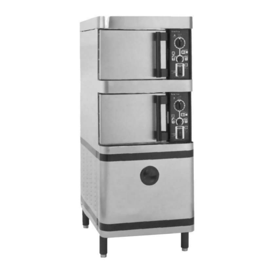
ELECTRIC STEAM COOKER
PLUS
STP-6E
OWNER'S MANUAL
01/07
An Employee Owned Company
35 Garvey Street
Tel: (617) 387-4100
Fax: (617) 387-4456
Outside MA Fax: (800) 227-2659
l
E-Mail: CUSTSERV@mfii.com
Everett
MA
02149
l
l
l
Toll Free: (888) 698-3188
l
Website: www.mfii.com
l
Advertisement
Table of Contents

Subscribe to Our Youtube Channel
Related Manuals for Market Forge Industries STEAM-TECH PLUS STP-6E


Summary of Contents for Market Forge Industries STEAM-TECH PLUS STP-6E
- Page 1 STEAM-TECH ELECTRIC STEAM COOKER PLUS STP-6E OWNER’S MANUAL Form Number: S-2464 01/07 An Employee Owned Company Printed in U.S.A. 35 Garvey Street Everett 02149 Tel: (617) 387-4100 Toll Free: (888) 698-3188 Fax: (617) 387-4456 Outside MA Fax: (800) 227-2659 E-Mail: CUSTSERV@mfii.com Website: www.mfii.com...
-
Page 2: Table Of Contents
TABLE OF CONTENTS 1. INTRODUCTION 6. MAINTENANCE • 1.1 To The Kitchen Manager ........1.1 • 6.1 General .............6.1 • 1.2 Description............1.1 • 6.2 Daily Cleaning ..........6.1 • 1.3 Cooking Capacities...........1.1 • 6.3 Preventive Maintenance ........6.1 • 1.4 Basic Functioning ..........1.1 •... -
Page 3: Introduction
Each compartment is equipped with identical controls. These controls allow it to be used in the “TIMED STEAM” mode, Market Forge Industries Inc. “CONSTANT STEAM” untimed mode, or the “STEAM & HOLD” 35 Garvey Street mode. -
Page 4: Installation
2. INSTALLATION 2.1 SETTING IN PLACE SERVICE CONNECTIONS - Electrically Operated The assembled Steam-Tech Plus Pressureless Steam Cooker Power Supply - Use wire suitable for at least is shipped bolted to a skid, with the cabinet feet shipped in a separate container. -
Page 5: Reversing The Doors
2. INSTALLATION DOmESTIC & ExpORT HEATER WIRING & RATINGS FIGURE 2.2 2.3 REVERSING THE DOORS the front of the unit. NOTE: The top hinge is slightly larger The Steam-Tech Plus Pressureless Steam Cooker has cooking than the bottom hinge. compartment doors which are reversible, for your convenience. Remove the 4 black plastic hole plugs from the front unit. - Page 6 2. INSTALLATION left door latch mounting holes. Slide the remaining (small) hinge into the top door bear- ing. To adjust the tension of the door latch tighten both nuts down until the springs are fully compresses then back Slide the door and hinge assembly down onto the hinge each nut off 1/2 turn.
-
Page 7: Initial Systems Inspection
3. INITIAL SYSTEMS INSPECTION 3.1 GENERAL DEMAND system is the means by which the Steam-Tech Plus This section contains information for you to test and familiarize monitors and creates steam. This system uses very sensitive yourself with the operation of the Steam-Tech Plus. sensors to monitor the minute steam fluctuations inside the cooking compartment. -
Page 8: Steam Suppression
3. INITIAL SYSTEMS INSPECTION CAUTION: THE TIMER IS USEFUL ONLY AS AN ALARM was opened. WHEN IN THE CONSTANT STEAM MODE. THE TIMER WILL COUNT DOWN, BUT IT WILL HAVE NO EFFECT ON NOTE: Repeat steps in section 3.2 through section 3.7 for both THE CONTINUOUS GENERATION OF STEAM, AS IT WILL the upper and lower cooking compartments to insure proper BE OVERRIDDEN BY THE CONSTANT STEAM BUTTON. -
Page 9: Operation
4. OPERATION 4.1 CONTROLS AND INDICATORS 4.2.3 SHUT DOWN The controls and indicators used to operate that Steam-Tech Plus pressureless steam cooker are listed and described in No special procedure is necessary for shutting the unit down. table 4.1 on this page. Their locations are called out in Figure Simply press the POWER switch into the OFF position. - Page 10 4. OPERATION FIGURE 4.1 CONTROL pANEL...
- Page 11 4. OPERATION FIGURE 4.2 DAILY CLEANING (SINGLE COOKING COmpARTmENT SHOWN) UPPER LOWER ITEM COMPARTMENT COMPARTMENT PART DESCRIPTION qTY. qTY. A-LA-CARTE TRAY E91-5782 COOKING COMPARTMENT DRAIN SCREEN E91-5718 DRIP/SPILL TROUGH SCREEN E91-5769 LEFT PAN SLIDE E91-5700 RIGHT PAN SLIDE E91-5698...
-
Page 12: Daily Cleaning
4. OPERATION 4.3 DAILY CLEANING ment by sliding it down onto its mounting tabs. After each period of daily operation (more frequently as re- Replace a-la-carte tray by sliding it back until it drops down quired to maintain cleanliness) the cooker should be thoroughly onto its mounting pins. -
Page 13: Trouble-Shooting
5. TROUBLE-SHOOTING 5.1 GENERAL The information in this section is intended to assist the operator, If the problem cannot be readily corrected without the use of maintenance and the service personnel in locating the source tools, the operator/maintenance person should contact the fac- of problems which may occur with the cooker. -
Page 14: Trouble-Shooting Guide
5. TROUBLE-SHOOTING GENERATOR CONTINUOUSLY CREATES STEAM (STEAM DEMAND LIGHT IS ALWAYS ON) Cooking compartment door out of alignment. Check alignment of door. Realign if necessary. Cooking compartment door gasket leaky. Check/replace door gasket. Pressure switch disconnected. Check to be sure all pressure switch connections are made. -
Page 15: Testing The Water Fill Relay
5. TROUBLE-SHOOTING PROCEDURE: Connect the jumper to terminals “G” and “H”. After a delay Turn off all power to the unit. of 4-5 seconds, the relay should switch and the LED will go OFF. Using the voltmeter touching the probes to terminals Select the controller to be tested. -
Page 16: Maintenance
6. MAINTENANCE 6.1 GENERAL The following sections set forth minimum preventive mainte- This section contains both preventive and corrective mainte- nance procedures which must be completed periodically to as- nance information. Preventive maintenance may be performed sure continued trouble free operation. by maintenance personnel at the establishment in which to cooker is installed. - Page 17 6. MAINTENANCE FIGURE 6.1 ExTERIOR STEAL-mETAL COVER pANEL AND FASTENERS ITEM PART DESCRIPTION qTY. LEG, BLACK, ADJUSTABLE E10-0631 FRONT COVER PANEL ASSEMBLY E91-5767 REAR COVER PANEL ASSEMBLY E91-5789 REMOVABLE VENT HATCH E91-5777 SIDE COVER PANEL ASSEMBLY E91-5778 FASTENERS 8-32 SLOTTED TRUSS HEAD MACHINE SCREW, 3/8” LONG, STAINLESS STEEL E08-3492...
-
Page 18: Cleaning The Steam Ventilation Ductwork
6. MAINTENANCE 6.5 CLEANING THE STEAM VENTILATION DUCTWORK Using detergent and a damp cloth, wipe clean the inside of The Steam-Tech Plus ventilation ductwork system is made up the vent access hatch. of a series of horizontal and vertical ducts. This series of duct- Reinstall vent access hatch onto the rear of the unit. - Page 19 6. MAINTENANCE FIGURE 6.2 ELECTRICAL pANEL ASSEmBLY ITEM PART DESCRIPTION qTY. DINRAIL RELAY MOUNTING RAIL 08-6515 FS-1 FUSE LOCK 08-6520 GND. LUG GROUNDING JUG 10-5220 PCB-1 WATER LEVEL CONTROL 08-6328 RAIL CLIP DIN RAIN RETAINER CLIPS 08-6516 RYL-1 RELAY 3PDT 08-6509 RYL-2 RELAY DPDT MAGNETIC LATCH...
- Page 20 6. MAINTENANCE FIGURE 6.3...
- Page 21 6. MAINTENANCE FIGURE 6.4 pRINCIpLES OF OpERATION SCHEmATIC...
- Page 22 6. MAINTENANCE FIGURE 6.5 SINGLE COmpARTmENT SYSTEm WIRING DIAGRAm...
- Page 23 6. MAINTENANCE FIGURE 6.6 SINGLE COmpARTmENT SYSTEm WIRING DIAGRAm...
-
Page 24: Control Panel Electrical Service Access
6. MAINTENANCE 6.7 CONTROL PANEL ELECTRICAL SERVICE ACCESS During normal usage, these should not need any attention. The control panel assembly is mounted onto the front of the unit. It houses all of the controls and indicators which are used Note that when the cooking compartment doors are revered, as to operate the cooker. -
Page 25: Door Latch Tension Adjustment
6. MAINTENANCE FIGURE 6.7 CONTROL pANEL ASSEmBLY Square the door to the unit by rasing or lowering the hinge 5/16” wrench. side of the door keeping the latch centered with the strik- Close and visually inspect the door again as described in step 8. -
Page 26: Door Handle Tension Adjustment
6. MAINTENANCE ment, remove the corresponding control panel. If latch is Remove the 6 screws, 3 from top edge and 3 from bottom mounted on the left side, remove left side panel. edge of door. Tighten both nuts down until the springs are fully com- Remove the door gasket, door gasket mounting plate and pressed. - Page 27 6. MAINTENANCE FIGURE 6.9 COOKING COmpARTmENT DOOR ASSEmBLY 6.12...
-
Page 28: Door Gasket Replacement
6. MAINTENANCE ITEM FIGURE 6.9 COOKING COMPARTMENT DOOR ASSEMBLY PART DESCRIPTION qTY. DOOR GASKET E91-5286 DOOR GASKET MOUNTING PLATE E91-5731 DOOR HANDLE E91-5745 DOOR INSERT E91-5766 DOOR SHELL E91-5729 HINGE BEARING, NYLON E08-2702 HINGE BRACKET, BOTTOM (SMALLER) E91-5436 HINGE BRACKET, TOP (LARGER) E91-5437 MAGNET E08-5027... -
Page 29: Solenoid Fill Valve Strainer Screen Cleaning .6.14
6. MAINTENANCE FIGURE 6.10 SINGLE ELECTRIC pOWERED STEAm GENERATOR ASSEmBLY 6.10 SOLENOID FILL VALVE STRAINER SCREEN CLEANING Unscrew screen plug from valve and remove screen. The solenoid fill valves contain a built in strainer screen inside Clean screen and reassemble screen and screen plug into the valve body. - Page 30 6. MAINTENANCE ITEM FIGURE 6.11 BLOWER BOX ASSEMBLY PART DESCRIPTION qTY. BLOWER E08-7501 BLOWER BOX E91-5737 BLOWER MOUNTING FLANGE E08-7501 BLOWER MOUNTING PLATE E91-5738 8-32 HEX NUT, STAINLESS STEEL, WITH NYLON INSERT E10-2396 #8 FLAT WASHER, STAINLESS STEEL E10-2408 10-32 SLOTTED TRUSS HEAD MACHINE SCREW, STAINLESS STEEL, 1/2” LONG E10-1764 FIGURE 6.11 BLOWER BOx ASSEmBLY 6.15...
- Page 31 6. MAINTENANCE FIGURE 6.12 TEmpERING TANK ASSEmBLY 6.16...
- Page 32 6. MAINTENANCE FIGURE 6.13 CHASSIS ASSEmBLY 6.17...
- Page 33 6. MAINTENANCE 6.18...
- Page 34 6. MAINTENANCE FIGURE 6.14 TUBING ROUTING 6.19...
- Page 35 6. MAINTENANCE 6.20...
Need help?
Do you have a question about the STEAM-TECH PLUS STP-6E and is the answer not in the manual?
Questions and answers