Table of Contents
Advertisement
Quick Links
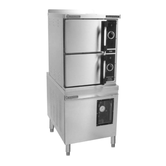
3500 & 3500 Power-Plus
INSTALLATION, OPERATION, MAINTENANCE, SERVICE AND PARTS MANUAL
FORM NO. S-4842 REV. D 08/11
OWNER'S MANUAL
MODELS:
Tel: (617) 387-4100 • Fax: (617) 387-4456 • Toll Free: (866) 698-3188 • Outside MA Fax: (800) 227-2659
Printed in U. S. A.
Improper installation, adjustment, alteration,
service or maintenance can cause property
damage, injury or death. Read the installa-
tion, operation and maintenance instructions
thoroughly before installing or servicing this
equipment.
Do not store or use gasoline or other flam-
mable vapors and liquids in the vicinity of
this or any other appliance.
Post in a prominent location, instructions to
be followed in the event the user smells gas.
This information shall be obtained by con-
sulting the local gas supplier.
□
3500
□
3500 Power-Plus
WARNING:
FOR YOUR SAFETY:
An Employee Owned Company
35 Garvey Street • Everett • MA 02149
E-mail: custserv@mfii.com • Web site: www.mfii.com
Advertisement
Table of Contents

Subscribe to Our Youtube Channel
Related Manuals for Market Forge Industries 3500


Summary of Contents for Market Forge Industries 3500
- Page 1 3500 & 3500 Power-Plus OWNER’S MANUAL WARNING: Improper installation, adjustment, alteration, service or maintenance can cause property damage, injury or death. Read the installa- tion, operation and maintenance instructions thoroughly before installing or servicing this equipment. FOR YOUR SAFETY: Do not store or use gasoline or other flam- mable vapors and liquids in the vicinity of this or any other appliance.
-
Page 2: Table Of Contents
COOKER CHECK-OUT ........2 ELECTRICAL FAULT ISOLATION GUIDE ..13 SHUT-DOWN PROCEDURE ......3 WIRING AND SCHEMATIC DIAGRAM (FOR REVERSING THE DOORS .........3 MODEL 3500 ONLY) ...........14 WIRING AND SCHEMATIC DIAGRAM (FOR OPERATION MODEL POWER-PLUS ONLY) ......15 OPERATING CONTROLS AND INDICATORS ...3 TIMER MOTOR ...........16 OPERATING PROCEDURES ......3... -
Page 3: Introduction
Market Forge Industries Inc. BASIC FUNCTIONING: 35 Garvey Street The Model 3500 may be operated with only one Everett, Massachusetts 02149-4403 compartment in use; or both may be used simultane- Telephone: (617) 387-4100 ously. -
Page 4: Installation
INSTALLATION ASSEMBLY: Equipment failure caused by inadequate water qual- The Pressureless Cooker is factory-mounted on a ity is not covered under warranty. cabinet base containing either a steam boiler or di- rect steam connection controls for the cooker. The CAUTION: assembled unit is shipped bolted to a skid, with cabi- PVC or CPVC are not acceptable materials for drains. -
Page 5: Shut-Down Procedure
OPERATING CONTROLS AND INDICATORS: OPERATING PROCEDURES: The controls and indicators required to operate the The 3500 Pressureless Steam Cooker defrosts fro- Pressureless Steam Cooker are listed in Table 1 on zen foods and cooks fresh and defrosted foods. Each page 5, together with a short functional description of cooking compartment permits selection of continuous each. -
Page 6: Steam Source Operating
Turn off buzzer, which sounds to indicate cooking is DRIP/SPILL TROUGH DRAINAGE: complete, by setting timer dial (1) to the OFF posi- The 3500 Pressureless Steam Cooker has a drip/spill tion. trough below the cooking compartment door. It will catch any condensate gathering on the front of the Open door sightly at first letting most of the steam unit when the door is opened. -
Page 7: Controls And Indicators
OPERATION TABLE 1 CONTROLS & INDICATORS (Refer to Fig. 1) ITEM DESCRIPTION FUNCTION Controls cooking up to 60 minutes for Timer/Constant Steam uses constant operation. Indicated when lit that the cooker is Indicator Light (Red) in operation. Buzzer (Not Shown) Signals end of cooking period. -
Page 8: Facts On Parade
OPERATION TEST KITCHEN BULLETIN MODEL 3500 PRESSURELESS COOKER FACTS ON PARADE Frozen vegetables should always be cooked in perforated 12” x 20” x 2 1/2” pans 7 1/2 lbs (34 kg) maxi- mum per pan. Frozen entrees should be underlined with a perforated pan for best results. If they are defrosted first, the heating time will be decreased. -
Page 9: Timer Settings
PRESSURELESS STEAM COOKING TIMER SETTINGS The 3500 Pressureless Cooker is a two compartment unit. Each compartment holds five 12” x 20” x 2 1/2” or three 12” x 20” x 4” pans. This unit enables the cook to prepare foods close to the time of service. The cooking times given are timer settings and should be set on a preheated compartment. - Page 10 OPERATION VEGETABLES APPROX. RECOMMENDED TIMER APPROX/ NO. FROZEN PAN SIZE, 12” x 20” NUMBER SETTINGS IN COOKED SERVINGS ITEM WT. PER PAN PERFORATED OF PANS MINUTES PER PAN Beans, Snap Green 6 lbs. 2 1/2” 18-22 25-30 or Waxed (2.7 kg) (65mm) 3 oz.
-
Page 11: Principles Of Operation
PRINCIPLES OF OPERATION GENERAL: these circuits is shown in Fig. 2 on page 5. The 3500 Pressureless Steam Cooker consists of two identical cooking compartments, one above the other, NOTE: Fig. 2 is strictly a pictorial schematic diagram in a single cabinet assembly. Each compartment is... -
Page 12: Steam Inlet Line
PRINCIPLES OF OPERATION is directed into the boiler (or direct-connected steam switch located inside the compartment. When the control) drain system. Steam inlet lines for compart- timer starts the cold water solenoids will energize. ments are equipped with normally closed solenoid valves operated by the electrical control circuits. -
Page 13: Pictorial Diagram Of Steam And Water
PRINCIPLES OF OPERATION Fig. 2 Pictorial Diagram, Steam and Water Circuits INDICATOR LIGHTS: by the proximity of a magnet within the door. When An indicator light is included for both compartments. the door is open, the switch contacts remain in the The light remains on (red) at all times when the co- open position. -
Page 14: Trouble-Shooting
TROUBLE-SHOOTING GENERAL: The information in this section is intended to assist ELECTRICAL FAULT ISOLATION: both the operator and service personnel in locating Correction of an electrical failure first requires isola- the general source of problems that may occur with tion of the fault to a single circuit or component. In the cooker. -
Page 15: Incoming Power
TROUBLE-SHOOTING The electrical trouble-shooting procedures that follow WARNING: require access to components and terminals of the Before removing control panel or checking connec- electrical control panel shown in Fig. 6 on page 21. tions and wiring, be sure that the circuit breaker for in- Electrical controls are reached by removing screws coming power is OFF. -
Page 16: Wiring And Schematic Diagram
TROUBLE-SHOOTING MODEL 3500 ONLY Fig. 3 Wiring and Schematic Diagram (for Model: 3500 ONLY) -
Page 17: Model Power-Plus Only)
TROUBLE-SHOOTING MODEL 3500 POWER-PLUS ONLY Fig. 4 Wiring and Schematic Diagram (for Model: 3500 POWER-PLUS ONLY) -
Page 18: Timer Motor
TROUBLE-SHOOTING Connect an ohmmeter between terminals 1 and 3. Connect an ohmmeter between the terminals of the switch. Rotate timer dial beyond the “0 Minute” point (any setting) to obtain a reading of zero ohms on the Actuate the switch by closing the cooking compart- ohmmeter. -
Page 19: Buzzer
TROUBLE-SHOOTING is not obtained, the switch is defective. at the coil wire terminals with the cooker compartment in operation. If voltage of 120 volts is present and the Shut off cooker, disconnect ohmmeter leads, and valve fails to open, the fault is in the valve coil. Defec- replace wires on switch terminals. -
Page 20: Cooking Compartment Cleaning
Market Forge Industries Inc. This section contains a complete listing of all re- 35 Garvey Street placeable parts of the 3500. For the purpose of parts Everett, Massachusetts 02149-4403 identification, the unit is broken down into functional Telephone: (617) 387-4100... -
Page 21: Cabinet Assembly
ILLUSTRATED PARTS LIST Fig. 5 Cabinet Assembly... - Page 22 INLET GASKET 10-9174 RELAY TUBE 91-6477 BRACKET, LINER HOLD DOWN 08-4978 BARB, 1/4” IPS FEMALE X 1/4” ID TUBE 08-4866 SPRAYER NOZZLE (3500 ONLY) 08-4833 REDUCING TEE, 1” X 1” X 1/4” IPS 08-1207 BARB, 1” IPS 91-7638 STIFFENER, BACK 91-7639...
-
Page 23: Door Assembly
ILLUSTRATED PARTS LIST Fig. 6 Door Assembly ITEM PART DESCRIPTION QTY. 91-5729 OUTER DOOR 91-5766 INNER DOOR 91-5731 GASKET RETAINING PLATE 91-5286 DOOR GASKET 91-5745 DOOR HANDLE 09-1608 STRIKER 08-5027 MAGNET 91-5901 MAGNET BRACKET 08-4600 COMPRESSION SPRING... -
Page 24: Control Panel Assembly
ILLUSTRATED PARTS LIST Fig. 7 Control Panel Assembly ITEM PART DESCRIPTION QTY. 98-3504 CONTROL PANEL 98-3507 ARTWORK, CONTROL PANEL 08-6464 60 MIN. TIMER 08-6541 TERMINAL STRIP 91-6471 BRACKET, TERMINAL STRIP 10-7395 BUZZER 08-3826 KNOB, TIMER 10-5052 LIGHT, RED, ON/OFF... -
Page 25: Condenser Assembly
ILLUSTRATED PARTS LIST Fig. 8 Condenser Assembly ITEM PART DESCRIPTION QTY. 91-7640 CONDENSER BRACKET 08-4821 CONDENSER SOLENOID (3500 ONLY) 08-4864 HOSE BARB, 90 , 1/8” IPS (3500 ONLY) 08-5009 TEE, 1/8 IPS x 1/4 ID HOSE (3500 ONLY) -
Page 26: Complete Condenser Assembly
BRAIDED STAINLESS STEEL HOSE 2 1/2” 08-4864 HOSE BARB, 90 , 1/8” IPS 08-1206 HOSE CLAMP 08-7923 TEE 1/8” NPT 08-4890 HOSE COUPLER, 1/8 IPS x 1/4 ID 91-6491 GROMMET 08-4866 SPRAY NOZZLE (3500 ONLY) 08-4821 CONDENSER SOLENOID (3500 ONLY) 91-7640 CONDENSER BRACKET... -
Page 27: 3500 Power-Plus
ILLUSTRATED PARTS LIST Fig. 10 3500 Power-Plus ITEM PART DESCRIPTION QTY. 10-9175 RELAY SOCKET, (ONE PER COMPARTMENT) 10-9174 CUBE RELAY, (ONE PER COMPARTMENT) 08-6502 PRESSURE SWITCH 98-4206 POWER SUPPLY, 5 VDC 97-6455 TIME DELAY RELAY...
Need help?
Do you have a question about the 3500 and is the answer not in the manual?
Questions and answers