
Related Manuals for Market Forge Industries ST-E


Summary of Contents for Market Forge Industries ST-E
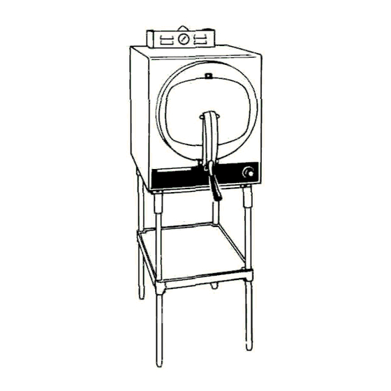
- Page 1 SERVICE & PARTS MANUAL ELECTRIC STEAM-IT STEAM COOKER, STYLE C MODEL: ST-E 35 Garvey Street Everett, MA 02149 Form Number 5143B 12/85 Printed in U.S.A. Tel. (617) 387-4100, Telex 94-9414, Cable MAFORCO...
- Page 2 HOW TO USE THIS MANUAL This manual contains maintenance and service instructions for the Style C, ST-E Electric Steam-It. Only ST-E Steam-Its which have serial numbers prefixed with the letter "C" may be serviced according to the instructions in this manual.
- Page 4 ST-E STEAM-IT STYLE C MASTER ILLUSTRATION PARTS LIST Item No. Description Part No. Item No. Description Part No. Baseplate Ass'y —Fixed 95-3301 47 Handle Bumper 10-0226 Transformer (440/480 V Units 10-5234 48 No 8-32 x 3/8 Binding Hd Screw Ty "Z" (st'n st'l)
- Page 5 THE DOOR GASKET THE BUZZER The function of the Buzzer is to signify to the operator that the Keep the gasket clean. With normal closing and locking of cycle of cooking has been terminated the door assembly, a steam-tight seal should be made between the door gasket and the door opening.
- Page 6 DOOR ADJUSTMENT 5. To replace the door assembly, reverse the step by step procedure described above. The door adjustment is located in the fulcrum casting at the base of the door opening. This adjustment employes the use of a DOOR LIFT SPRING REPLACEMENTS screw and locknut.
-
Page 7: Door Handle Assembly
DOOR HANDLE ASSEMBLY - PARTS LIST Item Description Part No. Item Description Part No. Door Handle Bearing Bracket ..95-0659 No. 10 - 32 Acorn Nut..10-2318 1/4" Shakeproof Lockwasher .. 10-2513 #10 Shakeproof Lockwasher. . . 10-2514 1/4"- 20 x 5/8" Rd. Hd. Screw ... 10-1731* Locking Screw .... - Page 8 FULCRUM & DRAIN ASSEMBLY ROLLER ASSEMBLY The Fulcrum and Drain Assembly is located at the lower Built Prior to 10/85 (Items 5, 6, 7, 8 & 9) Built after 10/85 front of the cooking cylinder and furnishes a sturdy (Items 2, 8, 9, 13 & 14) The Roller Assembly must be kept anchorage for the door locking system of the door handle free-rolling at all times Should this assembly be allowed to Also provided in this assembly is a means of adjustment fo r...
-
Page 9: Connector
SAFETY VALVE The Safety Valve is set to automatically relieve the cooking compartment of excessive pressure build-ups by opening at a point between 15 1/2 Ibs and 16 Ibs CHECKING SAFETY VALVE If the Safety Valve should leak continually with a pressure build-up, or should it cause an interruption of the cooking cycle prematurely (less than 15'/2 Ibs on the steam gauge), it must be determined to be defective and be replaced However, the steam gauge should first... - Page 10 ST-E EXHAUST VALVE -Parts List...
- Page 11 5149...
-
Page 12: Low Water Cut-Off
CLEANING EXHAUST SILENCER HOW IT WORKS The Exhaust Silencer should be removed and cleaned periodically The copper tube which extends from the top of the cylinder to the As the cooking chamber is exhausted of steam through the silencer, rear portion of the Timer Control Switch constantly reflects internal impurities can build up from food particles Cleanings should be cylinder steam pressures upon the Timer Control Switch's built-in frequent enough to prevent clogging to occur For this reason, the... -
Page 13: Element Control Switch
ELEMENT CONTROL SWITCH TIMER CONTROL SWITCH Should a lower cylinder cooking pressure be desired, adjust the larger dial (D) by inserting a screwdriver into the slot (B) found at its ELEMENT CONTROL SWITCH center and turning it slightly counterclockwise to lower the pressure The Element Control Switch, located under the removable front Clockwise rotation will increase the pressure. -
Page 14: Pilot Light
RECALIBRATION PROCEDURE Check this new sotting by operating the Steam It through a trial cycle and note the pressure gauge reading at the precise moment when the contactor Set the larger dial (D) of the Element Control Switch at "clicks out" This should be at 14 Ibs. (Check may also 14 Ibs. -
Page 15: Washer
ITEM NO. PART NO. DESCRIPTION ITEM NO. PART NO. DESCRIPTION 90-2657 Rear Panel St. Steel 90-3210 Bracket Magnetic Catch 90-3013 Rear Panel St. Steel Kit 10-5561 Magnetic Catch 90-2661 Side Panels R & L St. Steel 10-1869 No. 10-32 x 1/2" Flat Head Screw 90-9039 Side Panels R &... -
Page 16: Wiring Diagram
TROUBLE SHOOTING GUIDE TROUBLE POSSIBLE CAUSE CORRECTION Steam-It fails to operate at all. (No 1. Blown fuse. 1. Replace fuse. If it blows again, check that pressure build-up). source of electric supply is 60 Amp. 2. Wiring is defective. 2. Check all wiring. Repair or replace. 3. - Page 17 5156...
- Page 18 UNITS BUILT PRIOR TO 6/79...
- Page 19 FOR 3 PHASE-4 WIRE. CONNECTION: 380/22O OR 4l5/240V CONNECT Ll L2 L3 TO THE. 3 lNCOMING PHASES CONNECT N TO THE INCOMING NEUTRAL CONNECT E TO THE INCOMING EARTH (GROUND WIRE) CONNECT CONTROL CIRCUIT WIRE C1 TO L3 CONNECT CONTROL CIRCUIT WIRE C2 TO N FOR 3 PHASE-3 WIRE CONNECTION : (380V OR.
Need help?
Do you have a question about the ST-E and is the answer not in the manual?
Questions and answers