
Related Manuals for GAI-Tronics Auteldac 5


Summary of Contents for GAI-Tronics Auteldac 5
- Page 1 Installation and User Guide Auteldac 5 Zone 1 Ex Certified Hazardous Area Telephone GAI-TRONICS A Division of Hubbell Ltd Document 502-20-0149-001 iss1, Mar 2015, CN36575-041...
-
Page 2: Table Of Contents
Possible Operating Faults ............26 Fault Finding & Field Repairs ............27 TECHNICAL SPECIFICATIONS ..........27 Hazardous Area Certification ............27 Regulatory Compliance and Related Standards ......29 Physical characteristics ............... 32 Environmental specifications ............32 Recycling information..............33 Auteldac 5... -
Page 3: Safety Information
European directive 2003/10/EC on the minimum health and safety requirements regarding the exposure of workers to the risks arising from physical agents (noise). Auteldac 5... -
Page 4: Product Description
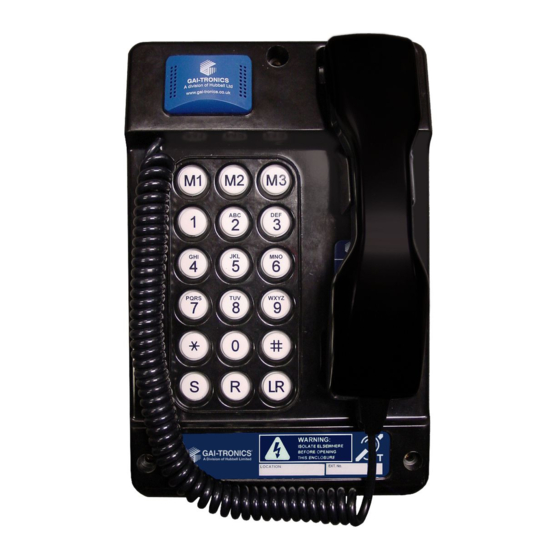
PRODUCT DESCRIPTION Rear case Main PCB Ringer Keypad User terminals Handset Gland entries Front case Auteldac 5 Hazardous Area Telephone at a glance Auteldac 5... -
Page 5: Features
2.1 FEATURES Auteldac 5 is an Ex certified telephone built to withstand arduous industrial atmospheres and environmental extremes. Features include: IEC Ex zone 1 certified for safe operation in hazardous areas • Carbon loaded glass filled polyester body - rugged and corrosion •... -
Page 6: Installation
Standard stainless steel cord: 755mm (29.7in). Other cord lengths are available as special options: contact GAI-Tronics for details. 3.2 Pre- installation The Auteldac 5 telephone is connected by hard-wiring - (unlike a plug and socket on internal telephones). Because of this, installation must Auteldac 5... - Page 7 See section 3.4.2 for details. Cable entries - Auteldac 5 has 2 cable entry gland positions. • Before installing, give consideration to the options available and review the alternative connection schemes in section 3.4.8 to...
- Page 8 8. Take care when inserting the selected gland into the threaded cable entry hole. Follow the gland manufacturer’s instructions particularly with respect to sealing, installation and earthing. 9. After the glands have been fitted, select the required mounting method and follow the appropriate instructions below. Auteldac 5...
-
Page 9: Mounting Methods
Retain the cover to refit prior to putting the telephone into use. 5. Pass the cable through the gland and tighten, following the gland manufacturer’s instructions. 6. Continue the installation procedure with the connection of individual wires from the cable as described under sections 3.4 onwards. Auteldac 5... - Page 10 Pole-side Mounting Kit No 100-02-0208-001 This accessory kit is for mounting GAI-Tronics telephones on to the side of round poles of 100mm to 200mm diameter, or on to square or rectangular section uprights of 100mm to 150mm across the mounting surface.
-
Page 11: Connections And Cabling
RESULT IN AN UNSAFE INSTALLATION AND VIOLATE THE CONDITIONS OF THE CERTIFICATION. The connections to the Auteldac 5 are made via 2 terminal blocks below the main PCB. The cabling between the entry glands and the terminal blocks is covered by a terminal cover, secured by 2 screws as shown. Remove this cover to allow access to the terminals. - Page 12 There are two sets of telephone line terminals – connected in parallel to allow the connection of other approved equipment in parallel with Auteldac 5 without the need for a junction box. Note that the order of terminals is reversed between the two sets. The two sets of terminals are interchangeable.
- Page 13 3.4.3 Gland continuity connection Auteldac 5 is provided with 2 earth bonding screws which can be used as a continuity connection between glands if 2 metal glands are used. If the unit does not have a headset socket, reverse one of...
- Page 14 Loud V.Loud 54.5 The relay fitted to the Auteldac 5 has a continuous current rating of 3A. It has been brought to our attention that some beacons, whilst having a current rating well below this figure, actually generate current spikes far in excess of this during making and breaking of the relay contacts.
- Page 15 Where beacons with greater than 5 joule flash intensity are • required, the beacons should be purchased directly from GAI- Tronics, who will ensure compatibility with the Auteldac 5 and that certification parameters are not compromised. 3.4.5 Hook Switch State Indicator Contact...
- Page 16 The terminal cover must be secured in place before re- assembling the telephone prior to use. The terminal cover provides the required isolation between the cabling in the rear section and the circuitry in the front section and is critical to the product's certification. Auteldac 5...
- Page 17 Other apparatus Alternative options for using the parallel line terminals for connecting other approved apparatus in parallel with Auteldac 5 – using a multiple pair cable fed through one gland or alternatively using separate cables each fed through its own gland. Earth continuity connection between glands shown.
- Page 18 The terminal cover must be secured in place before re- assembling the telephone prior to use. The terminal cover provides the required isolation between the cabling in the rear section and the circuitry in the front section and is critical to the product's certification. Auteldac 5...
-
Page 19: Option Settings
3.5 Option Settings Auteldac 5 has three functions that have optional settings (Australian versions have a fourth option setting in addition). These are set using DIP switches on the internal circuit boards as described below. The telephone casing must be open to set these options. - Page 20 SW2-4 Pulse dialling, Pulse dialling, SW2-4 make/break make/break 33ms/66ms 40ms/60ms 3.5.4 Call Timer The call timer is set by SW3 on the keypad PCB as follows: SW3-1 Call will terminate No call timer after 7 minutes. Auteldac 5...
-
Page 21: Reassembling The Telephone Enclosure
There is a keyway on each connector to help. Do not forcibly fit the connector(s). IMPORTANT – FAILURE TO ENSURE THE CORRECT ORIENTATION OF THE CONNECTOR(S) WILL VIOLATE THE CONDITIONS OF THE CERTIFICATION Auteldac 5... - Page 22 NOTE: earth straps and smaller ribbon cable are only fitted on versions which have a headset socket. 3. Upon installation, care should be taken to ensure that incoming cables are cleanly routed with a view to maintaining segregation from the Auteldac 5...
- Page 23 IMPORTANT - DAMAGED INSULATION WILL VIOLATE THE CONDITIONS OF THE CERTIFICATION. 6. Tighten the three screws firmly to secure the front case to the rear. 7. Auteldac 5 is now ready for use. Auteldac 5...
-
Page 24: Operation
To end a call, replace the handset in its cradle. • To receive a call, lift the handset when ringing is heard. • Take care, when using either the handset or optional headset, not to • allow cables to tangle or snare around the body or neck. Auteldac 5... -
Page 25: Keypad Functions (18-Button Versions Only)
To program a number: Lift the handset • Press S • Enter the required digits • Press S again • Press the required memory button, M1, M2 or M3 • Replace the handset • Auteldac 5... -
Page 26: Headset Operation
4.2 Headset Operation (refer to section 1 for hazard warning) The Auteldac 5 can be supplied fitted with a headset panel, permitting hands-free operation using a suitable, certified headset. To use: 1. Insert headset plug into marked connector, observing keyway. -
Page 27: Maintenance
The headset interface of the Auteldac 5 has been certified as intrinsically safe. Therefore, it is permissible to connect and disconnect the headset in a hazardous area. MAINTENANCE The Auteldac 5 is based on highly reliable integrated circuits. Under normal operation, the telephone is maintenance free. -
Page 28: Fault Finding & Field Repairs
Additional holes drilled in casing • 5.3 Fault Finding & Field Repairs The Auteldac 5 contains no user serviceable parts and in the event of damage or failure must be replaced with a tested telephone of the correct type. Refer to section 5.2 for a list of possible fault conditions. - Page 29 Additionally, dust certified variants certified to: IEC 60079-31:2013 Explosive atmospheres Part 31: Equipment dust ignition protection by enclosure "t" Edition: 2 A copy of the IECEx certificate is available from www.gai-tronics.co.uk. 6.1.3 ATEX Hazardous Area Certification Certificate number: Baseefa14ATEX0362 Certification details: Gas certified variants (BLUE certification label): °...
-
Page 30: Regulatory Compliance And Related Standards
Additionally, dust certified variants certified to: EN60079-31:2014 Explosive atmospheres Part 31: Equipment dust ignition protection by enclosure "t" A copy of the ATEX certificate is available from www.gai-tronics.co.uk. 6.2 Regulatory Compliance and Related Standards Auteldac 5 is fully compliant with the following: 6.2.1 European Directives:... - Page 31 6.2.1.1 CE Declaration of Conformity Auteldac 5...
- Page 32 PSTN in Europe 6.2.4 Australian standards Australian versions of Auteldac 5 are compliant with the following: AS/NZS CISPR 22 – Information technology equipment – Radio disturbance characteristics – Limits and methods of...
-
Page 33: Physical Characteristics
Tested to ETS 300-381 The GAI-Tronics Quality Management System has been approved by LRQA to ISO9001. Certificate No. 861888 6.3 Physical characteristics... -
Page 34: Recycling Information
Business users should contact their suppliers and check the terms and conditions of the purchase contract and ensure that this product is not mixed with other commercial waste for disposal. Auteldac 5... - Page 35 Auteldac 5...
- Page 36 The policy of GAI-Tronics is one of continuous improvement, therefore the Company reserves the right to change specifications without notice. The contents of this publication are confidential, are the property of GAI-Tronics, and may not be reproduced, wholly or in part, without their written permission. E&OE.
Need help?
Do you have a question about the Auteldac 5 and is the answer not in the manual?
Questions and answers