
Related Manuals for EBARA TH Series


Summary of Contents for EBARA TH Series
- Page 1 End Suction Centrifugal TH Series Operating Instructions, Installation & Maintenance Manual EBARA Pumps Americas Corporation...
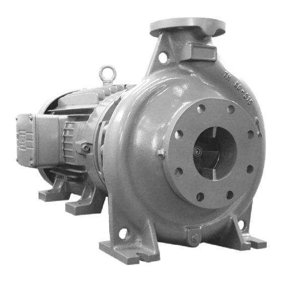
- Page 2 EBARA pump. This pump is a TH Series, end suction centrifugal pump. It is capable of being used in a variety of applications including heating, air conditions, pressure boosting, cooling water transfer and non-potable water supply.
- Page 3 Operating, Installation, and Maintenance Safety Information (Continued) PACKAGE CONTENTS Be sure all parts have been furnished and that nothing has been damaged in shipment. The catalog lists all parts included with package. A packing list packed with pump, also lists contents.
- Page 4 Operating, Installation, and Maintenance Model TH Selection Chart Synchronous Speed 1750 RPM 25-150 50-160 100-200 25-200 50-200 100-250 32-125.1 50-250 100-315 32-125 50-315 100-400 32-160.1 65-125 125-200 32-160 65-160 125-250 32-200 65-200 125-315 32-350.1 65-250 125-400 32-250 65-315 150-200 40-125 80-160 150-250 40-160...
- Page 5 Operating, Installation, and Maintenance Model TH Selection Chart Synchronous Speed 3500 RPM 25-150 50-125 25-200 50-160 32-125.1 50-200 32-125 50-250 32-160.1 50-315 32-160 65-125 32-200 65-160 32-350.1 65-200 32-250 65-250 40-125 80-160 40-160 80-200 40-200 80-250 40-250 100-160 40-315 100-200 5 ...
- Page 6 Operating, Installation, and Maintenance Model THD Specifications Standard Optional Size Suction x Discharge TH-25-150 – 1¼” x 1” Consult factory for ANSI Compatible TH-25-200 – 1½” x 1” threaded connections Flange TH-32 – 2” x 1¼” TH-40 – 2½” x 1½” TH-50 –...
- Page 7 Operating, Installation, and Maintenance Model TH Sectional View Frame Mounted Item Number Part Name Material No. Casing Cast Iron Casing Cover Cast Iron Impeller Cast Iron Impeller Wear Ring 410 SS Shaft SAE 1045 Steel 039-1 Steel 039-2 Steel Shaft Sleeve 304 SS Impeller Nut 316 SS Bearing Housing...
- Page 8 Operating, Installation, and Maintenance Model THD Sectional View Closed-Coupled Item Number Part Name Material Casing Cast Iron Casing Cover Cast Iron Impeller Cast Iron Impeller Wear Ring 410 SS Steel Shaft Sleeve 304 SS Bushing Steel Casing Wear Ring 410 SS Mechanical Seal Ceramic/Graphite/Buna 115-1...
- Page 9 Operating, Installation, and Maintenance Rules for Safe Installation LOCATION OF UNIT – The pump should be installed as near to the liquid source as is practical so that the static suction head (vertical distance from the center line of the pump to water level) is maximized, and so that a short, direct suction pipe may be used.
- Page 10 Operating, Installation, and Maintenance Rules for Safe Installation (Continued) ALINGMENT PROCEDURES(continued) Check axial clearance of coupling at every 90° increment. (see figure 4) Axial clearances should be examined using a feeler gauge. Use a straight edge to check radial alignment at every 90° increment. Place the straight edge across the two rims of the sleeve coupling to check there is no light path between the edge and the coupling.
- Page 11 Operating, Installation, and Maintenance Rules for Safe Installation (Continued) PIPING - Pipes must line up and not be forced into position. Piping should be independently supported near the pump so that no strain will be placed on the pump casing. Where any noise is objectionable, pump should be insulated from the piping with vibration isolation devices.
- Page 12 Operating, Installation, and Maintenance Start and Operation STARTING – Please follow below procedure to start pump, Check if the pump-motor assembly is aligned and securely fastened to the baseplate. Check the piping is free of leakage, especially the suction piping. Connect and run auxiliary pipelines and connections, if any.
- Page 13 GASKETS - Volute, suction pipe and discharge pipe gaskets should be checked for damage. Replace if necessary. NOTE If replacement parts are ordered, please furnish the following information to your EBARA distributor: EBARA Model number and Serial number on the nameplate. Item numbers Description of pump part 13 ...
- Page 14 Operating, Installation, and Maintenance THD Assembly Instruction Pump Assembly – THD Closed Coupled WARNING Power Make certain the motor is not connected to a power source. Do not install or assemble the pump on a motor connected to a power source. Severe injury could occur if the motor Step 1 ...
- Page 15 Operating, Installation, and Maintenance THD Assembly Instruction (Continued) Pump Assembly – THD Closed Coupled Step 6 Place the casing cover (item 011) on bracket (item 803). Use hex head bolts (item 120‐2). Step 7 Insert the key (item 039) into motor shaft. Step 8 - A Insert the impeller wear ring (item 025) on the impeller (item 021), using a soft face hammer. Step 8 - B ...
- Page 16 Operating, Installation, and Maintenance THD Assembly Instruction (Continued) Pump Assembly – THD Closed Coupled Step 10 - A Place the casing (item 001) on the casing cover (item 011). Fasten with hex head bolts (item 120‐1) 16 Rev 10/2018 ...
- Page 17 Operating, Installation, and Maintenance TH Assembly Instruction (Continued) Pump Assembly – TH Frame Mounted Step 1 Heat the bearings (item 849) to perform the assembly on the shaft (item 031). Note: If possible, we recommend using an induction heater to facilitate assembly of bearings. Step 2 Place the gaskets (item 117) in the bearing cover (item 845). *Do not use any adhesive type to place the gasket (item 117). ...
- Page 18 Operating, Installation, and Maintenance TH Assembly Instruction (Continued) Pump Assembly – TH Frame Mounted Step 6 Insert the stationary part of mechanical seal (item 696) into case cover (item 011) using grease or another type of lubricant. Use a soft face tool to avoid damages. After the stationary part is in place, clean the face with an alcohol wipe. Step 7 Use hex head bolts (item 120‐1) to fix the case cover (item 011) to bearing housing (item 051). ...
- Page 19 Operating, Installation, and Maintenance THD Assembly Instruction (Continued) Pump Assembly – TH Frame Mounted Step 11 Insert the key (item 039) on the shaft (item 031). Step 12 Install the impeller (item 021). Lock the shaft in place and tighten the shaft nut (item 048) with Loctite. Step 13 Install the back‐pull‐out assembly in the casing (item 001). Install the casing bolts (item 120‐2) and tighten them. ...
-
Page 20: Troubleshooting
Operating, Installation, and Maintenance Troubleshooting WARNING Service Work Only certified personnel should perform service work on these pumps and motors. Trouble Possible Cause Probable Remedy Motor Fails to Start Loss of supply voltage Check voltage across all phases above circuit breakers Pump motor branch circuit breaker Check voltage below circuit open or tripped... - Page 21 Troubleshooting Trouble Possible Cause Probable Remedy Motor fails to come up to Low or incorrect voltage Check voltage and T1, T2, and T3 speed in control panel and at motor leads Incorrect connection at motor Check for proper lead connections at motor, compare with connection diagram on motor Mechanical overload...
Need help?
Do you have a question about the TH Series and is the answer not in the manual?
Questions and answers