Table of Contents
Advertisement
Advertisement
Table of Contents

Related Manuals for Hunter Node


Summary of Contents for Hunter Node
- Page 1 Battery-Operated Controller Owner’s manual and programming instructions...
-
Page 3: Table Of Contents
To Wire DC Solenoids to the NODE To Mount the NODE to a Valve (Figure 1) . . . . . . . . . . . . . . . . . . . . . . . . . . . . . . . . . . .6 MOUNTING THE NODE . -
Page 4: Node Features
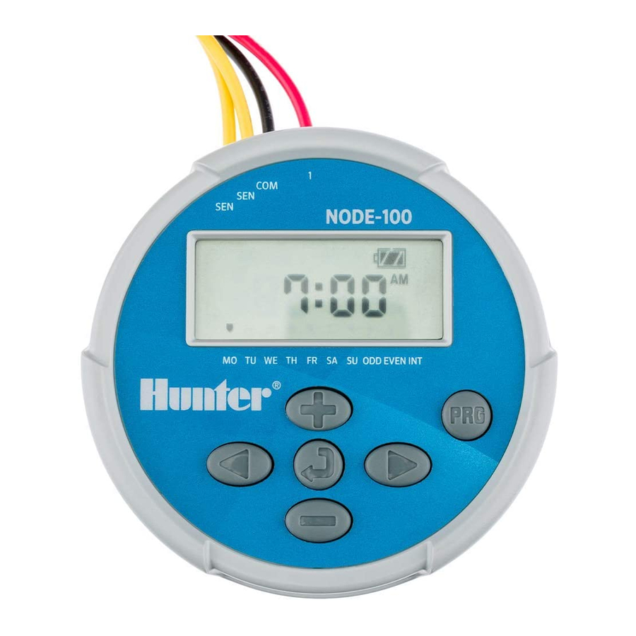
NODE FEATURES • Simple push button programming • Single station model with DC latching solenoid . 2,4, or 6 station models also available (solenoids not included) . • Large Liquid Crystal Display (LCD) with easy to understand icons • Operates on a standard 9-volt alkaline batteries (1 or 2 for extended battery life) •... -
Page 5: Node Components
This section provides a brief overview of some of the components LCD Display of the NODE . Each item will be discussed in further detail later . Main Display – Indicates all program information However, this section can be helpful in getting acquainted with the different options available . -
Page 6: Connecting The Battery/Batteries
To Install the Battery/Batteries operate the valves and program the controller . The controller can Unscrew the rear body of the NODE body to gain access to operate using either a single 9-volt battery or using two 9-volt the battery compartment . -
Page 7: Attaching Solenoids
Attach one red wire from each solenoid to the corresponding station wire (red lead) from the NODE . The station numbers are identified on the face of the NODE . Secure all wire NOTE: Must use DC Latching Solenoids connections with waterproof connectors . -
Page 8: To Mount The Node To A Valve (Figure 1)
A specially designed valve mounting clip makes installation a the NODE . The purpose of this sensor is to stop watering when snap . A protective rubber cover is provided to prevent dirt from weather conditions dictate . -
Page 9: Setting The Date And Time
. During a short period of inactivity the display will shut off Hunter controllers a dial is used to scroll between the programming to retain battery power . Pressing any button will wake up the NODE functions, however, on the NODE the button is used to quickly to the Idle Mode . -
Page 10: Setting Watering Start Times
PROGRAMMING (CONTINUED) All 4 numbers are shown with the two numbers on the left Press the button to proceed to the next programming flashing, representing the hour . Use the buttons to function or allow controller to return to idle mode . change the hour . -
Page 11: Setting Watering Days
PROGRAMMING (CONTINUED) Setting Watering Days Once ODD or EVEN mode is activated it will be the only cursor shown on the display . Press the button until the icon is displayed . The program letter (A, B, or C) will be displayed . Arrows point at the specific days of the week in which watering will occur . -
Page 12: Turning The System Off
PROGRAMMING (CONTINUED) the run times displayed . Example, if 20 minute run times are Use the buttons to select the desired station and programmed and then the seasonal adjustment is changed buttons to set the manual watering time for the from 100% to 50%, the run times displayed will be 10 minutes . -
Page 13: Sensor Operation
, as well as many other interrupt type devices/sensors that do not require power . Simply connect the sensor to the NODE controller by cutting the yellow wire loop and connecting to the sensor wires . NOTE: NODE is not compatible with Hunter Wireless Rain-Clik ®... -
Page 14: Advanced Programming Features
ADVANCED PROGRAMMING FEATURES All advanced programming functions are initiated from the Idle Easy Retrieve Memory Mode, which shows the time, day of the week, and battery life This function allows the user to save a preferred program to indicator on the display . If something is flashing on the display then permanent memory in the controller, to be restored at any time . -
Page 15: Setting Master Valve Operation
The multi station NODE models (NODE-200, NODE-400, and designated period from 1-99 days . At the end of the programmable NODE-600) are capable of being programmed with the use of a off period the controller will resume normal operation . -
Page 16: Hunter Quick Check
This circuit diagnostic procedure can quickly identify “shorts” commonly caused by faulty solenoids or when bare common wire touches a bare station control wire . To initiate the Hunter Quick Check procedure: From the Idle Mode, press and hold the , and buttons . -
Page 17: Troubleshooting Guide
Faulty solenoid . Replace solenoid . Incompatible solenoid . Must use Hunter DC Latching Solenoid (P/N 458200) or other compatible DC latching solenoid . Automatic irrigation does not Controller in System Off mode . Verify that controller is programmed for start at start time. -
Page 18: Specifications
Dimensions: 3 ½"(89 mm) diameter, 2 ½"(64 mm) high Sensor inputs: 1 Power source: 9-volt alkaline battery (1 or 2 for extended battery life) Activates DC latching solenoids operating 9-11VDC (Hunter PN 458200) Operating temperature: 0ºF to 140ºF or - 17ºC to 60ºC Approvals... - Page 20 Hunter Industries Incorporated The Irrigation Innovators • © 2011 Hunter Industries Incorporated 1940 Diamond Street San Marcos, California 92078 USA • LIT-560 5/11 www.hunterindustries.com...
Need help?
Do you have a question about the Node and is the answer not in the manual?
Questions and answers
The rear body of the node will not unscrew, so that I can replace the battery. What do I do?
To unscrew the rear body of the Hunter Node to replace the battery, follow these steps:
1. Ensure the controller is off.
2. Carefully unscrew the rear body from the front half.
3. Avoid water entering the battery compartment.
4. Remove the old battery/batteries.
5. Insert new battery/batteries into the battery tray and connect them to the controller.
6. Align the seal marker on the rear half with the front half to ensure a proper seal.
7. Screw the rear body back onto the front half securely.
This ensures proper functionality and prevents water damage.
This answer is automatically generated
Program A1 won't start but Program B1 does start. Why does this happen
How to removed a programmed watering day from the system?
Will my hunter node stay on when the battery is low ? In other words - if the unit is watering when the battery runs out will the solenoid stay open?
I can manually water 6 stations but I only see 4 stations when I am programming the watering times. How do I add the other stations to the program?