Table of Contents
Advertisement
Advertisement
Table of Contents

Related Manuals for KAT VR WALK


Summary of Contents for KAT VR WALK
- Page 1 KAT WALK VR Omni-directional Treadmill User Manual...
-
Page 2: Table Of Contents
Caution Starting Installation List of Items Installation Instructions Tool Preperation Installing the KAT WALK VR Omni-Directional Mobile Treadmill Installing the Mechanical Structure Instructions for Base Plate Holder Caution Installing the Foam Edge Protectors Installing the KAT WALK Magnetic Side Plates... - Page 3 Installing the Main Body of KATVR-Foot Sensor Dismantling the Main Body of KATVR-Foot Sensor Dismantling and Replacement Dismantling and Replacement of KAT WALK VR Omni-directional Treadmill Dismantling of Outer Shell Dismantling of Mechanical and Electrical Structure Instructions for Replacing KAT SHOES...
-
Page 4: About The User Manual
4 About the User Manual About the User Manual This User Manual contains all the information necessary for the installation and use of KAT WALK VR Omni-directional Treadmill The following signs are used in the Manual to indicate useful and important information: Caution. -
Page 5: Declaration
Safety Reminder As the use of the product by players weighing more than 100kg may result in destructive damage to KAT WALK, which in turn leads to potential safety risks. Therefore, those players should not use KAT WALK for the safety of themselves and the service life of KAT WALK. -
Page 6: Maintenance
Maintenance of base plate Once KAT Shoes match the materials of the KAT WALK base plate, there will be a fixed friction coefficient, which is the balance point for the best experience. Thus, abrasion to the base plate will influence the product experience and the service life of the base plate. -
Page 7: Product Introduction
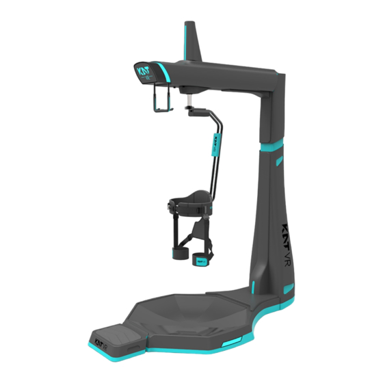
Product Introduction KAT WALK is a VR multi-direction mobile platform, which is also called VR treadmill. It breaks the virtual and real-life space limit, enabling users in extremely small space in reality to carry out 360° boundless movements in the virtual world through the combination of different components including the VR head-mounted display. -
Page 8: Kat Shoes
Product Introduction KAT SHOES are specially designed for the KAT WALK base plate. For the best game experience with the feeling of a natural walk, it is necessary to have a fixed ideal friction coefficient, which can be exactly provided by KATWALK. KAT WALK produces the foot curves and the displacement in human’... -
Page 9: Kat Shoes Cover
Product Introduction KAT SHOES COVER is the dedicated cover designed for the KAT WALK base plate. For the best game experience with the feeling of a natural walk, it is necessary to have a fixed ideal friction coefficient, while KAT WALK produces the foot curves and the displacement in human’... -
Page 10: List Of Items
22-24, screw box. Installation Instructions Please carefully read the relevant information provided in this Manual before installing the KAT WALK. As the product is quite heavy, please arrange more than three male adults for the installation. -
Page 11: Installing The Mechanical Structure
11 Starting Installation Installing the KAT WALK Multi-Direction Installing the Mechanical Structure 1. Place the base plate on a flat and open floor and use the spanner to adjust the base plate holder to prevent the plate from sliding. 2. Turn the metal hinges on the baste plate towards outside. - Page 12 12 Starting Installation 4. At least two persons lift the support pillar and place it at the location on the base plate as shown in the figure. Turn the hinges to direct the holes on the hinges at the screw holes on the support pillar, and re-install the bolts unscrewed at the last step.
- Page 13 13 Starting Installation 8. One person holds the support pillar, while two other persons turn the girder so that it rotates from a lying position (position 1) to a 90° angle (position 2). Place the bolt at the connection between the girder and the support pillar in the washer and fasten it.
- Page 14 14 Starting Installation 10. As shown in the figure, use the M5 screw to fix the cable at the corresponding position at the girder head (note: the top cable hole faces the front). 11. Unscrew the screw on the top cover off the shell. Install the top cover to the front end of the girder and use the unscrewed screw to fasten it, as shown in the figure.
- Page 15 15 Starting Installation 13. As shown in the figure, install the shell at the girder tail, put the three-in-one cable and the KATVR-Encoder cable through the shell and tighten them with the R-shaped clips. Plastic shell 2 at the girder tail Plastic shell 1 at the girder tail Orientation of the girder head...
- Page 16 1 6 Starting Installation 15. Installing the ground plug: as shown in the figure, install the grounding plug onto the support pillar and tighten the screws. Note: The screws have been installed onto the support pillar upon delivery and the grounding plug is included in the accessory box.
- Page 17 finish the installation. 20. Installing the pedals: As the upper surface of the KAT WALK base plate is concave and to enable users to better use our equipment, pedals that perfectly match the base plate are added under the support of the railings on the upper end of the girder.
-
Page 18: Instructions For Base Plate Holder
fixing it. Please do tighten the two nuts when fixing the KAT WALK. 1. When moving the KAT WALK, turn the upper nut on the base plate holder clockwise to move the nut down, and turn the lower nut counter clockwise to move the nut up. With the base plate holder shortened, the KAT WALK can be moved. - Page 19 Installation of KAT WALK Magnetic Side Plates Our product is equipped with the KAT WALK magnetic Side Plates for aesthetics and protection for the mechanical structure. Install the magnets to the installation surface on the left and the right of the base plate.
-
Page 20: List Of Included Sensors
20 Starting Installation Connection of KAT SENSORS List of Included Sensors Welcome to use a combination of KAT-SENSORS, and the Sensors you have received consist of the following components: 9 KATVR-Back Sensor Already installed to the connecting rod KATVR-Foot Sensor KATVR-Central Sensor Port for the KATVR-Top Sensor on the side Wireless receiver... - Page 21 21 Starting Installation Pairing Sensor The KATVR-Central and the KATVR-Back Sensor can only be used after being paired, and the two KATVR-Foot Sensor can only be used after being paired with the wireless receiver. Pairing of KATVR-Central and KATVR-Back Sensor The KATVR-Central and the KATVR-Back Sensor are paired when the six-digit dialers are dialed to the same position.
-
Page 22: Katvr-Foot Sensor
22 Starting Installation KATVR-Foot Sensor Six-digit red dialer Charging port Working indicator Charging indicator Switch button 3.5MM jack Caution Working indicator: red means it is not connected to the wireless receiver; blue means it is connected to the wireless receiver; flashing means a low charge level. Charging indicator: red means it is being charged;... -
Page 23: Wireless Receiver
23 Starting Installation Wireless Receiver Working status indicator USB A type male connector Six-digit red dialer Caution Working indicator: red means that it is not connected to the two KATVR-Foot Sensors or only connected to one KATVR-Foot Sensor; blue means it is connected to both of the KATVR-Foot Sensors. -
Page 24: Katvr-Central Sensor
24 Starting Installation KATVR-Central Working status indicator USB type A male connector KATVR-Encoder connecting cable port Six-digit red dialer Caution KATVR-Encoder working indicator: red means it is not connected to the KATVR-Back Sensor; blue means it is connected to the KATVR-Back Sensor. -
Page 25: Katvr-Back Sensor
25 Starting Installation KATVR-Back Sensor Working status indicator Charging status indicator Red button switch Micro USB charging port Six-digit red dialer Caution Red indicator: when it is on, it means the power supply to the KATVR-Back Sensor is normal but it is not connected to the KATVR-Central. Green indicator: when it is on, it means the KATVR-Back Sensor is connected to the KATVR-Central. -
Page 26: Connecting Sensors
26 Starting Installation Connecting Sensors 1. Dial the 6-digit red dialer of KATVR-Back Sensor to match the 6-digit red code of KATVR-Central Sensor. When dialing, note the distinction of the digital direction and the position of ON on the encoder. 2. -
Page 27: Power Switch
27 Starting Installation Power Switch Upon confirming the proper installation and connection of the product, press the power button for all the devices a. Check if the handles are fully charged. You may check the control handle battery charge level when not running any program or upon opening the main control panel of the system. - Page 28 28 Starting Installation Checking the Status of Sensor Indicators Location Indicator Red Blue Off Location Indicator Blue Off KATVR-Central Sensor normal KATVR-Central Sensor KATVR-Central power supply and running, normal power supply, Not connected to Working indicator Sensor not connected to the connected to the the PC KATVR-Relay...
- Page 29 3. Using a display cable that is too long (≥ 10 meters) may cause signal degradation which leads to failing to display your content. when doing venue decoration, please note that control cable length according to the situation . The PC running the KAT WALK must have the following software: Operation System:...
- Page 30 C) record the MAC address, contact KAT after-sales staff to bind the operation (provided that you have access to the KAT entertainment platform login permissions) CAUTION: Click on the official website of the official website "KAT WALK self-adaptation" words can jump to the download page...
-
Page 31: Logging Into Kat Entertainment Platform
31 Starting Installation Logging Into KAT Entertainment Platform 1.1.Double click the KAT entertainment platform icon and type in the username and password to log into the platform. 2. Enter the platform page, where the left side shows the category of games and the QR code of the Company, and the user may choose the game based on his/her preference. - Page 32 32 Starting Installation 2. Select the game and click “Enter details” to view the introduction of the game for more details. If the game is not installed to the computer yet, please click “Install” on the right side of the interface to install the game. While downloading and installing games is free of charge, a certain number of K coins will be consumed when playing the game.
-
Page 33: Game Settings
33 Starting Installation Game Settings How to Enter the Game Settings Page On the right side of the main interface, the gears area is the button to access game settings. The administrator may set up the game by entering the page of game settings. KAT will preset the parameters for the game software and please do not change them randomly. - Page 34 DM: threshold value of one KATVR-Foot Sensor Static: When the player finishes wearing the equipment and stands upright on the KAT WALK, the staff member will click “Static” and it will show a successful setting of the static status, which will be defined as the static value.
-
Page 35: Calibration Settings
1. Place the HTC VIVE head-mounted display (Not included with this version, it needs to be purchased separately) above the girdle set, and make sure the orientations of the display front, the girdle opening and the KAT WALK are consistent. - Page 36 36 Starting Installation 6. Choose the “Stand only” mode. 7. Click “Next” . 8. Click the “Calibrate central point” .
- Page 37 37 Starting Installation 9. Click “Next” after finishing the calibration. 10. Key in the distance between the head-mounted display and the floor: 110cm, and click it to calibrate the floor. 11. Click “Next” after finishing the calibration.
- Page 38 1. Make sure the orientations of the head-mounted display front, the girdle set and the KAT WALK are consistent during the calibration. 2. Do not randomly move the KAT WALK or the base station after the settings. Please re-do the set-up if you move the KAT WALK or the base station.
-
Page 39: Static Value Settings
2. A player of 150-180cm tall and weighing no more than 100KG is required to put on the girdle set and stand upright on the WALK. Click the icon of “Static” and it will show a successful setting of the static status, which will be defined as the static value. -
Page 40: Quitting The Game
40 Starting Installation Quitting the Game 1.Turing off during Click the “Close” button at the upper right corner of the page to turn off the game. Click “Quit” at the upper right corner of the page and it will prompt a box requesting you to confirm whether to quit the game. - Page 41 41 Starting Installation 2. Game over When the game is over, the page will pop up a window indicating that the time is up. Click “Confirm” to end the game and “Play again” to restart the game, and an equivalent amount of K coins will be deducted. Turning Off...
-
Page 42: Help Center
42 Starting Installation Help Center The Help button is located on the upper right part of the page. Click it to enter the self-help repair service page under the technical support on the KAT official website. You may view the introduction of the game and the videos and texts for common operations in this page. - Page 43 43 Starting Installation Click the drop-down box for the “Introduction of the game” and you will see the list for all the games on the platform. Choose a game and you will be able to view the basic introduction and the instructions of the game. Click the drop-down box for the “Videos of Installation and Use”...
-
Page 44: Putting On The Equipment
2. Make sure the girdle set and leg set are tightened for the safety of the player. 3. For the best experience during the first time, it is suggested that the player has a trial walk of 1-2 minutes before the experience. - Page 45 45 Starting Installation Installation and Dismantling of KAT SHOES COVER Sensors Fast Replacement of KATVR-Foot Sensor A fast replacement module has been designed in the structure of the IMU sensor for an easier replacement of IMU sensor on the shoes cover. The replacement can be done in fast way through the turning of the IMU main body and the buckle.
- Page 46 46 Starting Installation Installation and Dismantling of KAT SHOES Sensors Installation of KATVR-Foot Sensor: Insert the buckle of the KATVR-Foot Sensor into the external elastic belt of the Shoes and make sure the two sides of the buckle are inserted into the belt respectively, as shown in the figure: Installation of the Main Body of KATVR-Foot Sensor: 1.
-
Page 47: Dismantling The Main Body Of Katvr-Foot Sensor
47 Starting Installation Installing the KATVR-Foot Sensor: Insert the buckle of the KATVR-Foot Sensor into the external elastic belt of the Shoes and make sure the two sides of the buckle are inserted into the belt respectively, as shown in the figure: Dismantling the Main Body of KATVR-Foot Sensor: Turn the KATVR-Foot Sensor counter-clockwise and pull it out. -
Page 48: Dismantling And Replacement Of Kat Walk Vr Omni-Directional Treadmill
1. Plug out all the DC cables connected to the power socket. 2. Turn the base plate holder and move the KAT WALK to a flat and open field. 3. Unscrew the bolt on the installation panel of the connecting rod to dismantle the rod. -
Page 49: Instructions For Replacing Kat Shoes
49 Starting Installation Instructions for Replacing KAT SHOES It is advised to replace the wheel at the rear part of the KAT SHOES if it is loose or cannot roll properly. It is advised to replace the sliders on the sole of the KAT SHOES if they are severely abraded. As the slider in the front is more prone to abrasion than the other one, they may be swapped before the replacement. -
Page 50: Steps For Replacing Wheels
50 Starting Installation 3. Take off the old one and insert the new one in the same way. 4. Release the KAT SHOES, and the slot will return to the normal size. The new slider will automatically fit into the slot and the replacement is finished. -
Page 51: Instructions For Replacing Kat Shoes Cover
51 Starting Installation Instructions for Replacing KAT SHOES COVER It is advised to replace the slide block at the sole of the KAT SHOES COVER when it is loose or cannot roll properly. Steps of Replacing Slide Blocks 1. One hand holds the Cover, while the other pinches the slide block. Then bend the block outwards with strength. - Page 52 52 Starting Installation 4. One hand holds the Cover, while the other press the block into the block slot. Caution Make sure the orientations of the block upper and lower surface are consistent with those of other blocks when pressing it. 5.
- Page 53 ON on the dialer when dialing it. (If there is more than one KAT WALK within the same room, check if their values are the same. If so, please dial the...
- Page 54 54 Starting Installation Inconsistent Walking Orientation Between Figures in the Game and in the Reality Cause: The calibration is not done Solution: Complete the calibration by following the steps on page 33 of the User Manual. Cause: The base station or the equipment is moved Solution: Redo the calibration by following the steps on page 33 of the User Manual.
- Page 55 55 Starting Installation Unable to Download the Game Cause: Network connection error Solution: Check if the network connection is normal Cause: Insufficient storage of the C drive Solution: Check the remaining space of the C drive. If it is small, clean up the drive. Cause: Error in the game download Solution: Enter the windows⸺downloadgame file to find the corresponding game file.
- Page 56 ON on the dialer when dialing it. (If there is more than one KAT WALK within the same room, check if their values are the same. If so, please dial the dialers to make the values different.) Cause: KATVR-Central or KATVR-Back Sensor error Solution: Replace the KATVR-Central or KATVR-Back Sensor .
- Page 57 57 Starting Installation The Game Character Cannot Turn Around Properly Cause: KATVR-Top Sensor error Solution: 1. .Check if the connection end of the KATVR-Top sensor connector is in good contact.Cut off the power supply to the KATVR-Central sensor and plug out and in the KATVR-Back sensor connecting cable on the KATVR-Central Sensor; 2.
-
Page 58: 58 Warnings
58 Warnings FCC Warnings This device complies with Part 15 of the FCC Rules. Operation is subject to the following two conditions: (1) this device may not cause harmful interference, and (2) this device must accept any interference received, including interference that may cause undesired operation. Changes or modifications not expressly approved by the party responsible for compliance could void the user's authority to operate the equipment. -
Page 59: Ic Warnings
EU Regulatory Conformance Hereby,we,Hangzhou Virtual And Reality Technology Co., LTD. declare that this equipment KATVR-KAT WALK is in compliance with the essential requirements and other relevant provisions of Directive 2014/53/EU.The declaration of conformity may be consulted at www.katvr.com...
Need help?
Do you have a question about the WALK and is the answer not in the manual?
Questions and answers