
Related Manuals for Kramer VP-727XL


Summary of Contents for Kramer VP-727XL
- Page 1 Kramer Electronics, Ltd. USER MANUAL Model: VP-727xl Universal Presentation Matrix Switcher / Scaler...
-
Page 2: Table Of Contents
About the VP-727xl Getting Started Quick Start Overview About HDMI Your VP-727xl Universal Presentation Matrix Switcher / Scaler Installing on a Rack Connecting the VP-727xl Connecting the VP-727xl Control Ports Connecting a PC (via RS-232) Connecting the AUDIO CONTROL Port... - Page 3 VP-727xl Communication Protocol VP-727xl Text Overlay Protocol Figures Figure 1: VP-727xl Universal Presentation Matrix Switcher / Scaler Front Panel Figure 2: VP-727xl Universal Presentation Matrix Switcher / Scaler Rear Panel Figure 3: Connecting the VP-727xl Figure 4: Connecting the INPUTS (an example)
- Page 4 Tables Table 1: Front Panel VP-727xl Universal Presentation Matrix Switcher / Scaler Features 8 Table 2: Rear Panel VP-727xl Universal Presentation Matrix Switcher / Scaler Features 10 Table 3: Features and Functions of the TextOverlay Application Table 4: Number of Buffers, Output Resolution and Maximum Display Height...
-
Page 5: Introduction
2 We recommend that you use only the power cord that is supplied with the machine 3 Download up-to-date Kramer user manuals from the Internet at this URL: http://www.kramerelectronics.com 4 The complete list of Kramer cables is on our Web site at http://www.kramerelectronics.com Introduction... -
Page 6: Quick Start
Getting Started 2.1 Quick Start This quick start chart summarizes the basic steps when connecting a VP-727xl: KRAMER: SIMPLE CREATIVE TECHNOLOGY... -
Page 7: Overview
Overview The VP-727xl Universal Presentation Matrix Switcher / Scaler is a true multi-standard video to graphics scaler and presentation switcher for a wide variety of presentation and multimedia applications. It consists of a very high quality scaler with many user-selectable pixel-rates including VGA (640x480),... - Page 8 3 The wipe can be from left to right, right to left, up or down, and the corner wipe can start from any corner. The speed of each transition can be adjusted 4 Processing amplification enables adjustment of different video and audio signal parameters Overview KRAMER: SIMPLE CREATIVE TECHNOLOGY...
-
Page 9: About Hdmi
High-Definition Multimedia Interface (HDMI) is an uncompressed all-digital audio/video interface, widely supported in the entertainment and home cinema industry. It delivers the highest high-definition image and sound quality. Note that Kramer Electronics Limited is an HDMI Adopter In particular, HDMI Provides a simple... -
Page 10: Your Vp-727Xl Universal Presentation Matrix Switcher / Scaler
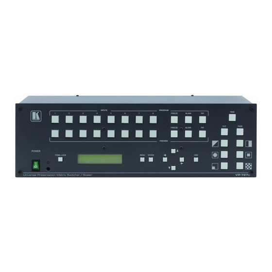
VP-727xl away from moisture, excessive sunlight and dust Your VP-727xl Universal Presentation Matrix Switcher / Scaler Figure 1 and Table 1 define the front panel of the VP-727xl: KRAMER: SIMPLE CREATIVE TECHNOLOGY... -
Page 11: Figure 1: Vp-727Xl Universal Presentation Matrix Switcher / Scaler Front Panel
Your VP-727xl Universal Presentation Matrix Switcher / Scaler Figure 1: VP-727xl Universal Presentation Matrix Switcher / Scaler Front Panel... -
Page 12: Table 1: Front Panel Vp-727Xl Universal Presentation Matrix Switcher / Scaler Features
Your VP-727xl Universal Presentation Matrix Switcher / Scaler Table 1: Front Panel VP-727xl Universal Presentation Matrix Switcher / Scaler Features Feature Function POWER Switch Illuminated switch for turning the unit ON or OFF IR Receiver / LED Green when the unit will accept IR remote commands; red in standby mode... -
Page 13: Figure 2: Vp-727Xl Universal Presentation Matrix Switcher / Scaler Rear Panel
Your VP-727xl Universal Presentation Matrix Switcher / Scaler Figure 2: VP-727xl Universal Presentation Matrix Switcher / Scaler Rear Panel... -
Page 14: Table 2: Rear Panel Vp-727Xl Universal Presentation Matrix Switcher / Scaler Features
Your VP-727xl Universal Presentation Matrix Switcher / Scaler Table 2: Rear Panel VP-727xl Universal Presentation Matrix Switcher / Scaler Features Feature BNC Connector G/Y BNC Connector BNC Connector BNC Connector BNC Connector BNC Connector G/Y BNC Connector BNC Connector BNC Connector... -
Page 15: Installing On A Rack
Installing on a Rack Installing on a Rack This section describes what to do before installing on a rack and how to rack mount. -
Page 16: Connecting The Vp-727Xl
RS-485 port, see section 7.3 The ETHERNET port, see section 7.4 1 Switch OFF the power on each device before connecting it to your VP-727xl. After connecting your VP-727xl, switch on its power and then switch on the power on each device... - Page 17 Connecting the VP-727xl Figure 3: Connecting the VP-727xl...
- Page 18 1 Figure 4 and Figure 5 show how to connect several sources, and the PREVIEW/PROGRAM OUT connectors, respectively 2 As this particular example describes. As the VP-727xl is universal, you can connect any type (format) of video to the inputs 3 Switch OFF the power on each device before connecting it to your VP-727xl.
-
Page 19: Figure 4: Connecting The Inputs (An Example)
HDMI connector to an LCD display VGA 15-pin HD computer graphics video connector to an analog display R/PR, G/Y, B/PB, HS and VS BNC OUTPUT connectors to a display Connecting the VP-727xl Betacam Set Top Box Video Player Source DVD Player... -
Page 20: Figure 3: Connecting The Vp-727Xl
4. Connect the power cord 5. If required, connect: A PC via RS-232, see section 7.1 The Kramer VP-727A Audio Switcher via the AUDIO CONTROL port, see section 7.2 The Kramer VP-727T Presentation Switcher Control Panel via the RS-485 port, see section 7.3 The ETHERNET port, see section 7.4... -
Page 21: Connecting The Vp-727Xl Control Ports
ETHERNET port, see section 7.4 7.1 Connecting a PC (via RS-232) You can connect a PC (or other controller) to the VP-727xl via the RS-232 port for remote control, and for upgrading the firmware. To connect a PC to a VP-727xl unit, using the Null-modem adapter provided... -
Page 22: Connecting The Audio Control Port
Connect the “ A” (+) PIN on the AUDIO CONTROL RS-485 rear panel port of the VP-727xl to the A (+) PIN on the RS-485 rear panel port of the VP-727A unit Connect the “ B” (-) PIN on the AUDIO CONTROL RS-485 rear panel... -
Page 23: Connecting Via Rs-485
A (+) PIN on the RS-485 rear panel port of the VP-727T unit Connect the “ B” (-) PIN on the RS-485 rear panel port of the VP-727xl to the B (-) PIN on the RS-485 rear panel port of the VP-727T unit If shielded twisted pair cable is used, the shield may be connected to the “... -
Page 24: Connecting The Vp-727Xl Via The Ethernet Port
7.4 Connecting the VP-727xl via the ETHERNET port To connect the VP-727xl via the ETHERNET port, do the following: Connect the ETHERNET port of the VP-727xl to the LAN port of your PC, via a crossover cable with RJ-45 connectors. -
Page 25: Understanding The Vp-727Xl
RGB/YUV, RGBS, RGsB, or RGBHV. INPUT 1 and INPUT 2 can also accept HDMI inputs. The VP-727xl is a universal presentation matrix switcher / scaler: you choose what type of source to connect to each input. You can connect different video types or the same or similar video types. -
Page 26: Figure 9: Example Showing The Use Of The Preview And Program Output
(not illuminated) momentarily (until the unit successfully locks to this input). The TAKE button should not be pressed until it lights up again, otherwise there will be a period of black during the transition Understanding the VP-727xl input 3. Set the OSD Settings as follows... -
Page 27: The Transition From Preview To Program
PROGRAM screen and the HD Component source is displayed on the PREVIEW screen. 8.3 Switching/Scaling of an Input The VP-727xl scales the selected sources VGA simultaneously. It switches seamlessly between sources using the selected special effects, which include cuts, fades, and wipes. Select the... -
Page 28: Activating The Pip
8.5 Locking and Unlocking the Front Panel To prevent changing the settings accidentally or tampering with the unit via the front panel buttons, lock your VP-727xl. Unlocking releases the protection mechanism. When the front panel is locked, control is still available via RS-232, the ETHERNET, and/or the CONTROL connector. -
Page 29: Using Text Overlay
8.6 Using Text Overlay The text overlay feature is accessed via the Application Program (AP) Running this AP with the PC connected to the VP-727xl lets you display text over the screen, with a rich feature set including text color and speed, transparency, text position and repetition. -
Page 30: Table 3: Features And Functions Of The Textoverlay Application
RS-232 connector Select VP725 when connected to a VP-725 series machine Select VP727 when connected to a VP-727xl (or VP-727) machine Type the desired text in the Message box Set the number of times that the text message will scroll across the screen... -
Page 31: Downloading The Textoverlay Program
If required, select the Buffer option 1 Go to http://www.kramerelectronics.com 2 This option can be used only if the Number of Buffer is other than 1 Understanding the VP-727xl Maximum Display Height According to Number of Buffers (0 to 2) to send varying text messages... -
Page 32: Connecting And Disconnecting The Textoverlay Program
To connect the TextOverlay program, do the following: 1. Open the TextOverlay program. The TextOverlay application screen appears 2. Select the VP-727xl check box. 3. Select the type of connection to be used RS-232, in the COM port box select the COM port you want to use... -
Page 33: Saving And Loading Settings
You can save current settings at any time or load a previously saved setting. When loading a setting and you need to reconnect it. 1 A saved setting also includes the connection type (TCP/IP or RS-232) Understanding the VP-727xl , the TextOverlay program automatically disconnects... -
Page 34: Operating The Vp-727Xl
The OSD superimposes a menu on the Preview screen from which you can control your VP-727xl. When the OSD front panel button is on, pressing the MENU button on the front panel or the Menu key on the infra-red remote control transmitter displays the first OSD screen screen. -
Page 35: Table 6: Preview And Program Setting Osd Menus
Confirm/Discard Confirms the action / cancels the action User Mode Setting Values will be used when user define is selected as output resolution (see section 9.1.1.3) 1 Independent Color Control Operating the VP-727xl Range Default 0 to 30 0 to 30... -
Page 36: Preview / Program Setting Calibration Screens
H-Position V-Position Saturation Frequency Phase Auto Gain Auto Image Figure 14: Program Setting Calibration Menu Operating the VP-727xl Level 3 Adjust the contrast Adjust the brightness Adjust the H-position Adjust the V-position Adjust the saturation Adjust the frequency Adjust the pixel phase... -
Page 37: Preview / Program Setting Output Test Pattern Screens
Figure 15 illustrates the Test Pattern screens 32 Gray Ramp Green Black Aspect Ratio 1 When selected, the test pattern is displayed after exiting from the OSD menu Operating the VP-727xl Level 3 Adjust the contrast Adjust the brightness Adjust the H-position Adjust the V-position... -
Page 38: Preview / Program User Mode Output Setting
Delay: Delay Set Current: Import the values of the currently selected output 1 These values will be used when “ User Define” is selected as the output resolution Operating the VP-727xl Figure 16: User Mode Setting User Mode Setting Definitions... -
Page 39: Transition Commands
Damping Range: 0 - 4 Effect Diagonal Option Wipe Circle Square Corner Chessboard Take Operating the VP-727xl Figure 17: Transition OSD Level 3 Top left, Bottom left, Top right, Bottom right Left to right, Right to left, Up, Down In, Out... -
Page 40: Audio Settings Commands
Audio-Follow-Video Audio follow video: follow, audio Fade Take Pressing causes the transition from preview to program (SWAP or FOLLOW) Operating the VP-727xl Figure 18: Audio Setting OSD Table 11: Audio Setting OSD Menus Level 3 Channel 1 to 8 (selects the input... -
Page 41: Utility Commands
1 For configuring the parameters of the OSD (on-screen display) window 2 Setting the Time Out to OFF will display the OSD continuously, until you manually close it Operating the VP-727xl Figure 19: Utility OSD Table 12: Utility OSD Setting... -
Page 42: Tcp/Ip Setting Commands
(9600/115200) commands. 9.1.4.2.1 Logo You can set the Kramer logo On or Off. When set to On (the default), it is displayed for 20 seconds upon initialization. If set to Off, it is disabled. 1 Dynamic Host Configuration Protocol Operating the VP-727xl... -
Page 43: Save Lock
Off, then you can still access the 8x2 Input buttons and the TAKE button, even if the Panel Lock is On 4 This is useful, for example, for configuring the machine for multiple presentations. Up to 8 presentation configurations can be saved in the machine’s memory Operating the VP-727xl . All parameters are saved/recalled, including the Information... -
Page 44: Operating Via The Front Panel Lcd Display
For example, to set the time out to 60 seconds via the LCD Display, using the front panel buttons, do the following: 1. Turn the VP-727xl unit ON, and press the OSD ON button (if selected). 2. Press the appropriate front panel OSD buttons (as defined in Figure 23). -
Page 45: Operating Via The Infra-Red Remote Control Transmitter
9.3 Operating via the Infra-red Remote Control Transmitter You can control the VP-727xl remotely, from the infra-red remote control transmitter (that has a range of up to 15 meters and is powered by two AAA size 1.5V DC batteries), as defined in Figure 24 and Table 14:... -
Page 46: Operating Via Ethernet
Figure 25: VP727xl Ethernet Application Main Dialog Box (Configuration Tab) 1 Or connect the serial port of your VP-727xl to the serial port of your PC (see section 7.1) 2 Or download the software from our Web site on http://www.kramerelectronics.com... -
Page 47: Figure 26: Vp727Xl Control Application Search Panel Screen
Figure 26: VP727xl Control Application Search Panel Screen Check your machine IP number, and click Insert to accept it. 1 You can also set the IP address via the OSD menu, see section 9.1.4.1 Operating the VP-727xl Figure 27: Configuration Tab... -
Page 48: Control The Vp-727Xl Via The Ethernet/Serial Port
The new IP address will appear on the screen 9.4.3 Control the VP-727xl via the Ethernet/Serial Port To control the VP-727xl via the Ethernet, do the following: 1. On the VP727xl Control Application screen, click the Control tab. The Control screen appears (see Figure 29). -
Page 49: Operating Via Rs-232
IP number or COM port A Message area, recording all the operations performed on the machine When clicking the Kramer icon, on the top right, the AP information appears, including the version number. By pressing the Remote Control button on the Control tab, you can operate the machine via the virtual remote controller interface, for your convenience. -
Page 50: Technical Specifications
19” (W), 9.3” (D), 3RU (H) rack mountable WEIGHT: 5.5 kg. (12.2 lbs.) approx. ACCESSORIES: IR remote control, power cord OPTIONS: Control panel 1 Specifications are subject to change without notice Technical Specifications of the VP-727xl KRAMER: SIMPLE CREATIVE TECHNOLOGY... -
Page 51: Vp-727Xl Communication Protocol
11 VP-727xl Communication Protocol This addendum includes the Communication Protocol for the VP-727xl: Set and Get command: Set Command: Y Control_Type Function Param 1 ... Param N CR Reply: Z Control_Type Function Param 1 ... Param N CRDoneCR Get Command:... -
Page 52: Table 17: Set Commands
0: Auto; 1: NTSC; 2: PAL; 3: PAL-M; 4: PAL-N; 5: NTSC 4.43; 6: SECAM; 7: PAL 60 -32 ~ 32 -32 ~ 32 1 F = Function VP-727xl Communication Protocol Table 17: Set Commands KRAMER: SIMPLE CREATIVE TECHNOLOGY Function Description Power... - Page 53 0: -; 1: + 1 ~ 4095 1 ~ 31 1 ~ 127 1 ~ 2047 0: -; 1: + VP-727xl Communication Protocol Function Description Preview Calibration H-Position Preview Calibration V-Position Preview Calibration Saturation Preview Calibration Frequency Preview Calibration Phase...
- Page 54 1365x1024; 10: 1400x1050; 11: 1600x1200; 12: 480p; 13: 576p; 14: 720p; 15: 1080i; 16: 1080p; 17: User define 131 0: 50; 1: 60; 2: 75 1 Param 2 = 0 ~ 999 VP-727xl Communication Protocol KRAMER: SIMPLE CREATIVE TECHNOLOGY Function Description Preview Output User Mode OCLK...
- Page 55 179 - 1 Param 2 = 0 ~ 999 2 Param 2 = 0 ~ 255, Param 3 = 0 ~ 255, and Param 4 = 0 ~ 255 VP-727xl Communication Protocol Function Description Program Output Test Pattern Program Output User Mode HT...
- Page 56 0: Swap 1: Follow 0: Black 1: Blue 0: Black 1: Blue 0: Off 1: On VP-727xl Communication Protocol Param2 0~32767 1->ON, 0->OFF bit 0: Program Channel 8 bit 1: Preview Freeze bit 2: Program Freeze bit 3: Preview Blank...
- Page 57 1: Audio Breakaway 0: Off 1: On 228 0 ~ 127 229 0 ~ 127 230 0 ~ 127 231 0 ~ 31 232 0 ~ 16 VP-727xl Communication Protocol Param2 Param3 Function Description Preview De- Interlace mode selection * only affects HDMI...
- Page 58 Control Type Param1 233 0 ~ 12 234 0 ~ 12 235 0 ~ 20 236 0 ~ 127 237 - VP-727xl Communication Protocol Param2 KRAMER: SIMPLE CREATIVE TECHNOLOGY Function Param3 Description Audio Bass Audio Treble 0 Audio Balance Audio Program...
-
Page 59: Vp-727Xl Text Overlay Protocol
12 VP-727xl Text Overlay Protocol Table 18 includes the Text Overlay Protocol. Each command includes three parameters: P1, P2 and P3. Table 18: Text Overlay Protocol of the VP-727xl Functions Command Display Buffer T12ED ** ** Configuration V-Position T13EC **... - Page 60 EXCLUSION OF DAMAGES The liability of Kramer for any effective products is limited to the repair or replacement of the product at our option. Kramer shall not be liable for: 1. Damage to other property caused by defects in this product, damages based upon inconvenience, loss of use of the product, loss of time, commercial loss;...
- Page 61 For the latest information on our products and a list of Kramer distributors, visit our Web site: www.kramerelectronics.com, where updates to this user manual may be found. We welcome your questions, comments and feedback. Safety Warning: Disconnect the unit from the power supply before opening/servicing.
Need help?
Do you have a question about the VP-727XL and is the answer not in the manual?
Questions and answers