
Related Manuals for Kramer VP-772


Summary of Contents for Kramer VP-772
- Page 1 USER MANUAL MODEL: VP-772 Presentation Matrix Switcher / Dual Scaler P/N: 2900-300295 Rev 2 www.kramerAV.com...
-
Page 4: Table Of Contents
Achieving the Best Performance Safety Instructions Recycling Kramer Products Overview HDCP Compliance for HDMI inputs Defining the VP-772 Presentation Matrix Switcher / Dual Scaler Installing in a Rack Connecting the VP-772 Wiring the RJ-45 Connectors Connecting the Balanced Stereo Audio Input and Outputs... - Page 5 Figures Figure 1: VP-772 Presentation Matrix Switcher / Dual Scaler Front Panel Figure 2: VP-772 Presentation Matrix Switcher / Dual Scaler Rear Panel Figure 3: Connecting the VP-772 Presentation Matrix Switcher / Dual Scaler Figure 4: TP PINOUT Figure 5: Balanced Stereo Audio Connection...
-
Page 6: Introduction
Room Connectivity; GROUP 10: Accessories and Rack Adapters; GROUP 11: Sierra Video Products; GROUP 12: Digital Signage; GROUP 13: Audio; and GROUP 14: Collaboration. Congratulations on purchasing your Kramer VP-772 Presentation Matrix Switcher / Dual Scaler. This product, which incorporates HDMI™ technology, is ideal for: ... -
Page 7: Getting Started
Avoid interference from neighboring electrical appliances that may adversely influence signal quality Position your Kramer VP-772 away from moisture, excessive sunlight and dust This equipment is to be used only inside a building. It may only be connected to other equipment that is installed inside a building. -
Page 8: Recycling Kramer Products
Kramer Electronics has made arrangements with the European Advanced Recycling Network (EARN) and will cover any costs of treatment, recycling and recovery of waste Kramer Electronics branded equipment on arrival at the EARN facility. For details of Kramer’s recycling arrangements in your particular country go to our recycling pages at http://www.kramerelectronics.com/support/recycling/. -
Page 9: Overview
Overview The Kramer VP-772 is an eight input high quality dual scaler with special effect transitions for the Rental and Staging and the Live Events market, and for other applications where a dual scaler is needed. It features DVI-U inputs (including analog, DVI and HDMI support) and stereo balanced audio signals. - Page 10 By RS-232 serial commands transmitted by a touch screen system, PC, or other serial controller The VP-772 is housed in a 19” 1U rack mountable enclosure, with handles and rack “ears” included, and is fed from a 100-240 VAC universal switching power supply.
-
Page 11: Hdcp Compliance For Hdmi Inputs
If an HDMI signal is HDCP protected, it can only appear on HDMI outputs that are connected to HDCP compliant displays. The VP-772 will not output a picture on an HDMI display that is not HDCP compliant; instead it will show a green screen. -
Page 12: Figure 1: Vp-772 Presentation Matrix Switcher / Dual Scaler Front Panel
Figure 1: VP-772 Presentation Matrix Switcher / Dual Scaler Front Panel Feature Function Metal handles (x2) Rigid handles IR Receiver Accepts IR remote commands IR LED Lights red when the unit accepts IR remote commands MODE Button Select the operation mode: AFV (audio follow video), Video or audio... -
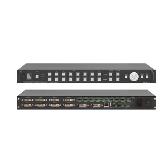
Page 13: Figure 2: Vp-772 Presentation Matrix Switcher / Dual Scaler Rear Panel
Ground connection; pins B (-) and A (+) are for RS-485. Set the TERM switch down if the VP-772 is the last unit on the RS-485 line. The ground connection is sometimes connected to the shield of the RS-485 cable. -
Page 14: Installing In A Rack
Installing in a Rack This section provides instructions for rack mounting the unit. VP-772 - Installing in a Rack... -
Page 15: Connecting The Vp-772
Kramer C-HM/DM 6’ or 10’). For lower resolutions you can connect the HDMI connector on a device to the DVI connector on the VP-772 via a HDMI-DVI adapter 5. Connect the AUDIO OUT 1 and OUT 2 Terminal Block connectors to up to two balanced analog audio acceptors, see Section 5.2... -
Page 16: Figure 3: Connecting The Vp-772 Presentation Matrix Switcher / Dual Scaler
7. Connect the power cord (not shown in Figure Figure 3: Connecting the VP-772 Presentation Matrix Switcher / Dual Scaler VP-772 - Connecting the VP-772... -
Page 17: Wiring The Rj-45 Connectors
This section defines the TP pinout, using a straight pin-to-pin cable with RJ-45 connectors. Figure 4: TP PINOUT EIA /TIA 568B Wire Color Orange / White Orange Green / White Blue Blue / White Green Brown / White Brown VP-772 - Connecting the VP-772... -
Page 18: Connecting The Balanced Stereo Audio Input And Outputs
Connecting the Balanced Stereo Audio Input and Outputs Figure 5: Balanced Stereo Audio Figure 6: Unbalanced Stereo Audio Output Connection Connection Figure 8: Unbalanced Stereo Audio Input Figure 7: Balanced Stereo Audio Input Connection Connection VP-772 - Connecting the VP-772... -
Page 19: The Osd Menu
The OSD Menu The OSD menu lets you set the VP-772 operation parameters. The OSD sub-menu operations appear in the OSD title, as shown in the example in Section 6.1: When in the main menu, the OSD title appears empty ... - Page 20 Data is saved per window and per input (to a dedicated input + window memory), as applicable The control buttons let you control the VP-772 via the OSD menu. Press the: MENU button to enter the menu and exit the menu ...
-
Page 21: The Input Menu
The Input Menu The Input menu lets you set each of the VP-772 input connector parameters (from 1 to 8): Figure 10: Input Menu Setting Function INPUT 1 to INPUT 8 Type Set the input type to HDMI, YUV, VGA or CV... -
Page 22: The Layout Menu
(see Section 7.2) (SbS) – dual window mode operation, both images are placed Split side-by-side with the same height (see Section 7.2) Customized Single Customized Dual VP-772 - The OSD Menu... - Page 23 Main or PiP window is HDCP encrypted. Note that the VP-772 will output a green screen if the output acceptor to which it is connected is not HDCP compliant, in the case that the video on the Main or PiP window is HDCP encrypted.
-
Page 24: The Program / Preview Menus
Set the vertical position of the image within the window (note that this is a volatile parameter when selecting Ratio Shift Mode > Auto) Window Customization Picture Brightness Set the brightness level Contrast Set the contrast level H Sharpness Select the horizontal sharpness level VP-772 - The OSD Menu... - Page 25 Any change in the input source may cancel the freeze and blank settings Set Mute to On to mute the audio output A mute icon appears on screen Power Save VP-772 - The OSD Menu...
- Page 26 Selecting the Correct Aspect Ratio You can configure the aspect ratio of any output image to fit your application. The VP-772 offers four different aspect ratio settings: Follow Input, Follow Output, Best Fit and Letterbox. Here is how each of these settings works.
-
Page 27: The Misc Menu
Note that the combination of threshold values (for red, green and blue) determines the chroma keying threshold. Any image with combined values of red, green and blue that are below this threshold will become transparent when chroma keying is enabled (see below). VP-772 - The OSD Menu... - Page 28 Program window show through. To use this feature it is recommended to set the Preview image as follows: use low-luminance colors for the background (the key image portion) and high-luminance colors for the logo. VP-772 - The OSD Menu...
-
Page 29: The Layout
In the transition mode you can setup the input, view it via the preview output and then switch it to the PROGRAM output. The VP-772 has two outputs: a PREVIEW output, and a PROGRAM output. Each of these outputs functions independently. An input is routed to the PROGRAM OUTPUT by pressing that PROGRAM INPUT front panel button. - Page 30 To set the Program input, repeat the above procedures using the Program menu If the transition mode is set to Swap, the Preview and Program inputs switch places. If Follow was selected, the Program input setting will follow the Preview setting and both will display the same input. VP-772 - The Layout...
-
Page 31: The Overlay Mode
The preset PiP configurations are available: Picture-in-Picture, with a smaller PiP window superimposed over a full main window image Picture + Picture, where both images appear side-by-side and the aspect ratios of both images are maintained VP-772 - The Layout... -
Page 32: Figure 14: Vga Superimposed Over Hdmi
When in the Overlay mode (set only via the OSD menu, see Section 6.3), select the main window by pressing a Program input front panel button and select the PiP window by pressing a Preview front panel button (see Figure 14). Figure 14: VGA superimposed over HDMI VP-772 - The Layout... - Page 33 4. In the Program/Preview menu, select Source. 5. Select an input (from 1 to 8). 6. Press the ENTER button. 7. Press the MENU a few times until you exit the OSD menu (changes are saved upon exit). VP-772 - The Layout...
-
Page 34: Controlling The Vp-772
8.2) The infrared remote control transmitter (see Section 8.3) Controlling via the Front Panel Buttons The VP-772 includes the following front panel buttons: Mode button to select AFV, Video or Audio switching (see Section 8.1.1) Program and Preview input selector buttons (see Section 8.1.1) - Page 35 (AFV with analog audio signal) An orange button indicates that only the video signal of that input is selected A red button indicates that only the audio signal of that input is selected VP-772 - Controlling the VP-772...
- Page 36 INPUT 1 and the video remains in INPUT 4. Press Preview INPUT 8 – the audio only switches to INPUT 8 and the video remains in INPUT 8 so that audio follows video and the button light green VP-772 - Controlling the VP-772...
- Page 37 Preview and Program inputs as follows, from: When in the Transition mode, pressing the ENTER front panel button in the Follow mode will switch the Program inputs to follow the Preview inputs: VP-772 - Controlling the VP-772...
- Page 38 8.1.3 Button Behavior in the Overlay Mode When in the overlay mode, the VP-772 does not pass the Preview audio to the output. In the Overlay dual mode the preview audio input button is dimmed: When in the Overlay mode, in the Single Window setting (see Section 6.3), the...
-
Page 39: Controlling Via The Osd Menu
You can connect to the VP-772 via an RS-232 connection using, for example, a PC. To connect the RS-232 terminal block on the rear panel of the VP-772 to a PC/controller connect the RS-232 9-pin D-sub port on your device to controller as... -
Page 40: Figure 16: Local Area Connection Properties Window
8.2.2.1 Connecting the Ethernet Port Directly to a PC You can connect the Ethernet port of the VP-772 directly to the Ethernet port on your PC using a crossover cable with RJ-45 connectors. This type of connection is recommended for identifying the VP-772 with the factory configured default IP address. -
Page 41: Figure 17: Internet Protocol Version 4 Properties Window
Protocol Version 4 (TCP/IPv4) depending on the requirements of your IT system. 5. Click Properties. The Internet Protocol Properties window relevant to your IT system appears as shown in Figure 17 Figure Figure 17: Internet Protocol Version 4 Properties Window VP-772 - Controlling the VP-772... -
Page 42: Figure 18: Internet Protocol Version 6 Properties Window
6. Select Use the following IP Address for static IP addressing and fill in the details as shown in Figure For TCP/IPv4 you can use any IP address in the range 192.168.1.1 to 192.168.1.255 (excluding 192.168.1.39) that is provided by your IT department. VP-772 - Controlling the VP-772... -
Page 43: Figure 19: Internet Protocol Properties Window
Connecting the Ethernet Port via a Network Hub or Switch You can connect the Ethernet port of the VP-772 to the Ethernet port on a network hub or using a straight-through cable with RJ-45 connectors. VP-772 - Controlling the VP-772... -
Page 44: Controlling Via The Infrared Remote Control Transmitter
Controlling via the Infrared Remote Control Transmitter You can control the VP-772 from the infrared remote control transmitter: Keys Function POWER Toggle the power save mode ON or RESET Press to reset to the default resolution (toggles between RESET TO XGA and... - Page 45 This distance can be extended to up to 60 meters when used with three extension cables (Model: C-A35M/A35F-50). Before using the external IR receiver, be sure to arrange for your Kramer dealer to insert the internal IR connection cable (P/N: 505-70434010-S) with the 3.5mm connector that fits into the REMOTE IR opening on the rear panel.
-
Page 46: Firmware Upgrade
The Firmware Upgrade Process Unzip the firmware files on your desktop to a folder named “VP-772” and then copy that folder to an empty, FAT32-formated USB memory stick (with at least 30Mb of free space) as a root folder. After copying the “VP-772” folder as a single root folder, the USB memory stick is ready to be used by attaching it into the device. -
Page 47: Figure 21: Firmware Upgrade - List Of Files To Upgrade
3. Click the ENTER button on the front panel. Wait for the completion of the upgrade process: Figure 22: Firmware Upgrade – Upgrade Process When the firmware upgrade is complete, the list of upgraded files appears: Figure 23: Firmware Upgrade – Upgrade Complete VP-772 - Firmware Upgrade... -
Page 48: Rollback
Figure 24: Firmware Upgrade – list of Files to Rollback 2. Press the ENTER button or the left arrow to proceed. Wait for completion of the procedure. 3. Reboot the machine by turning it off and then on again. VP-772 - Firmware Upgrade... -
Page 49: Technical Specifications
Power cord, rack “ears”, IR remote control, 2 DVI-A (M) to 5 BNC (F) Adapter INCLUDED ACCESSORIES: Cables (ADC-DMA/5BF-1), 2 DVI (M) to 15-pin HD (F) Adapters (AD-DM/GF) Specifications are subject to change without notice For the most updated resolution list, go to our Web site at http://www.kramerelectronics.com VP-772 - Technical Specifications... -
Page 50: Default Communication Parameters
Default gateway: 000.000.000.000 TCP Port #: 5000 UDP Port #: 50000 Maximum UDP Connections: Unlimited Maximum TCP Connections: Unlimited Full Factory Reset Factory Reset through the Misc menu item Use “Factory” command or #Y 0,561,1<CR> Protocol 3000 VP-772 - Technical Specifications... -
Page 51: Input Resolutions
10.2 Input Resolutions The VP-772 features eight DVI-U inputs. This section defines the input resolutions for each input. 10.2.1 CV Input Resolutions NTSC and PAL 10.2.2 Component Analog Video (YPbPr) Input Resolutions PC Input Resolutions NTSC 720_P50 1080_P30 1080_P50 720_P60... -
Page 52: Output Resolutions
10.3 Output Resolutions The VP-772 features two DVI-I outputs. This section defines the output resolutions for each output. 10.3.1 HDMI Digital Video Output Resolutions Technical Specifications of the HDMI Output Signal 640x480@60 1280x1024@50 1680x1050@60 1080p30 640x480@75 1280x1024@60 1920x1200@60 1080p50 800x600@50... -
Page 53: The Vp-772 Rs-232 Communication Protocol
® software (for example, the Windows HyperTerminal Application). 11.1 Using the Communication Protocol There are three different methods to control the VP-772 RS-232 or the Ethernet: Protocol commands mimicking the OSD, see Section 11.2 The button functions mimicking the remote controller buttons (as well as the front panel buttons), see Section 11.3... - Page 54 Main menu and the 3 item in the Layout submenu (see also Section 6.1). When navigating in the OSD MENU you will be able to see the Overlay Settings valid parameters. VP-772 - The VP-772 RS-232 Communication Protocol...
- Page 55 From Top Left / entry of the Inbound transition will be available Right to Left / depending on From Bottom Left the selected / Outbound effect Up / From Top Right / Horizontal VP-772 - The VP-772 RS-232 Communication Protocol...
- Page 56 800x600p60 800x600p75 1024x768p50 1024x768p60 1024x768p75 1280x768p50 1280x768p60 1280x800p60 1280x1024p50 1280x1024p60 1280x1024p75 1360x768p60 1366x768p50 1366x768p60 1400x1050p50 1400x1050p60 1600x900p60 1600x1200p50 1600x1200p60 1680x1050p60 1920x1200p60RB 480p60 576p50 720p50 720p59_94 720p60 1080p23_976 1080p24 1080p25, 1080p29_97 1080p30 1080p50 1080p59_94 VP-772 - The VP-772 RS-232 Communication Protocol...
- Page 57 H Image Shift [-50:+1023] 325 The value range is [-10:+1023] 326 dynamic, FW prevents V Image Shift exceeding of boundaries Picture Brightness [-512:+512] 341 Contrast [10:160] H Sharpness [-10:+10] V Sharpness [-10:+10] VP-772 - The VP-772 RS-232 Communication Protocol...
- Page 58 On / Off [0:1] 3833 Test Pattern Slide Bar Color Bar No Signal Gray Blue Black Auto Switching Audio Source [1-8] [1-8] AFV Source Embedded Analog Output [-80:+20] Volume Bass [-18:+18] [-18:+18] Treble [-18:+18] VP-772 - The VP-772 RS-232 Communication Protocol...
- Page 59 PALNC returns the Input video NTSC_8 format only 525p60 625p50 720p60 720p50 720p24 720p25 720p30 1080i60 1080i50 1080i100 1080p60 1080p50 1080p30 1080p23_976 1080p24 1080p25 2k50 2k60 640X480@60 640x480@72 640x480@75 848x480@60 640x480@85 800x600@56 800x600@60 VP-772 - The VP-772 RS-232 Communication Protocol...
- Page 60 Keying Chroma [0:240] In steps of 16 Keying Red Chroma [0:240] Keying Green Chroma [0:240] Keying Blue Chroma On / Off [0:1] Keying Luma Keying On / Off [0:1] FW Upgrade Upgrade Rollback VP-772 - The VP-772 RS-232 Communication Protocol...
-
Page 61: Protocol Table: Mimicking Remote And Front Panel Buttons
PROGRAM PREVIEW INPUT 3 INPUT 5 RESET PROGRAM PREVIEW INPUT 4 INPUT 6 PANEL LOCK PROGRAM PREVIEW INPUT 5 INPUT 7 MODE PROGRAM PREVIEW INPUT 6 INPUT 8 PREVIEW PROGRAM BLANK INPUT 7 VP-772 - The VP-772 RS-232 Communication Protocol... -
Page 62: The Protocol 3000 Common Operation Commands
.MINOR .BUILD .REVISION Read device build date BUILD-DATE? BUILD-DATE YYYY/MM/DD HH:MM:SS Read device protocol PROT-VER? PROT-VER 3000:MAJOR version .MINOR Set machine name NAME MACHINE_NAME NAME MACHINE_NAME RESULT Read machine name NAME? NAME MACHINE_NAME VP-772 - The VP-772 RS-232 Communication Protocol... - Page 63 PROTOCOL = TCP / UDP (transport layer protocol) PORT = Ethernet port to enter protocol 3000 commands. 1-65535 = User defined port 0 - reset port to factory default (50000 for UDP, 5000 for TCP) VP-772 - The VP-772 RS-232 Communication Protocol...
- Page 65 SAFETY WARNING Disconnect the unit from the power supply before opening and servicing For the latest information on our products and a list of Kramer distributors, visit our Web site where updates to this user manual may be found. We welcome your questions, comments, and feedback.
Need help?
Do you have a question about the VP-772 and is the answer not in the manual?
Questions and answers