Kramer VP-8x8 User Manual
8x8 vga / uxga matrix switcher
Hide thumbs
Also See for VP-8x8:
- User manual (41 pages) ,
- Quick start manual (2 pages) ,
- User manual (31 pages)
Table of Contents
Advertisement
Quick Links
Advertisement
Table of Contents

Related Manuals for Kramer VP-8x8


Summary of Contents for Kramer VP-8x8
- Page 1 Kramer Electronics, Ltd. USER MANUAL Model: VP-8x8 8x8 VGA / UXGA Matrix Switcher...
-
Page 2: Table Of Contents
Contents Contents Introduction Getting Started Overview Your VP-8x8 8x8 VGA / UXGA Matrix Switcher Connecting the VP-8x8 Connecting the VP-8x8 Rear Panel Controlling via RS-232 (for example, using a PC) Controlling via RS-485 Control Configuration via the Ethernet Port Setting the Ethernet Port and Utilities 5.5.1... - Page 3 Contents Figures Figure 1: VP-8x8 8x8 VGA / UXGA Matrix Switcher – Front and Rear View Figure 2: VP-8x8 8x8 VGA / UXGA Matrix Switcher – Underside View Figure 3: Connecting the VP-8x8 8x8 VGA / UXGA Matrix Switcher Figure 4: Connecting a PC without using a Null-modem Adapter...
- Page 4 Contents Tables Table 1: Front Panel VP-8x8 8x8 VGA / UXGA Matrix Switcher Features Table 2: Rear Panel VP-8x8 8x8 VGA / UXGA Matrix Switcher Features Table 3: VP-8x8 Underside Panel Features Table 4: Crossover Cable RJ-45 PINOUT Table 5: Straight-through Cable RJ-45 PINOUT...
-
Page 5: Introduction
2 Downloadable from our Web site at http://www.kramerelectronics.com 3 Previously known as the IR-1 / IR-1-01 4 Download up-to-date Kramer user manuals from our Web site at http://www.kramerelectronics.com 5 The complete list of Kramer cables is on our Web site at http://www.kramerelectronics.com... -
Page 6: Overview
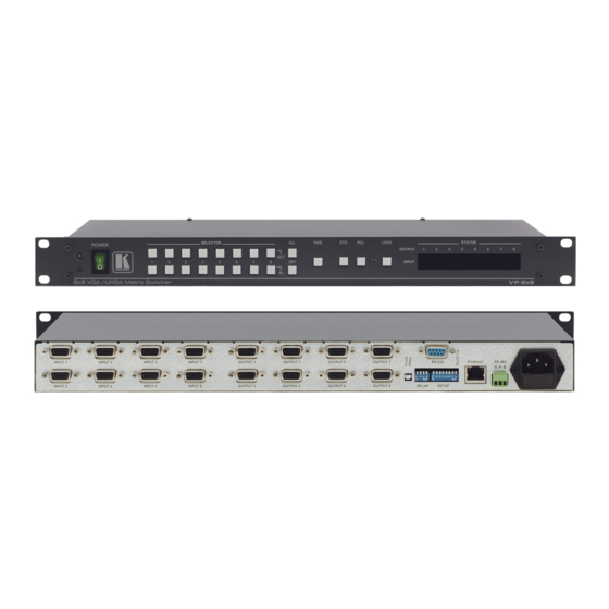
Your VP-8x8 8x8 VGA / UXGA Matrix Switcher Figure 1, Table 1 and Table 2 define the VP-8x8 8x8 VGA / UXGA Matrix Switcher. Figure 2 illustrates the underside of the VP-8x8 unit, and Table 3 defines the underside features. -
Page 7: Figure 1: Vp-8X8 8X8 Vga / Uxga Matrix Switcher - Front And Rear View
Your VP-8x8 8x8 VGA / UXGA Matrix Switcher Figure 1: VP-8x8 8x8 VGA / UXGA Matrix Switcher – Front and Rear View Enlarged View Figure 2: VP-8x8 8x8 VGA / UXGA Matrix Switcher – Underside View... -
Page 8: Table 1: Front Panel Vp-8X8 8X8 Vga / Uxga Matrix Switcher Features
Your VP-8x8 8x8 VGA / UXGA Matrix Switcher Table 1: Front Panel VP-8x8 8x8 VGA / UXGA Matrix Switcher Features Feature Function IR Receiver The red LED is illuminated when receiving signals from the Infra-red remote control transmitter POWER Switch... -
Page 9: Connecting The Vp-8X8
Table 2) and DO NOT push in the underside Flash Program “Reset” button. These are only used for upgrading to the latest Kramer firmware (see section 7) 2 When less than eight outputs are required, connect only those outputs of the VP-8x8 that are required, and leave the other outputs unconnected... -
Page 10: Figure 3: Connecting The Vp-8X8 8X8 Vga / Uxga Matrix Switcher
Connecting the VP-8x8 RS-232 Computer Graphics Source 1 Display 1 Computer Display 8 Graphics Source 8 Figure 3: Connecting the VP-8x8 8x8 VGA / UXGA Matrix Switcher KRAMER: SIMPLE CREATIVE TECHNOLOGY... -
Page 11: Controlling Via Rs-232 (For Example, Using A Pc)
Connecting the VP-8x8 5.2 Controlling via RS-232 (for example, using a PC) To connect a PC to the VP-8x8 unit, using the Null-modem adapter provided with the machine (recommended): Connect the RS-232 DB9 rear panel port on the Master VP-8x8 unit to... -
Page 12: Controlling Via Rs-485
“ G” (Ground) PIN on one of the units (for example, on the RC-3000) 2. Set the VP-8x8 unit as Machine # 1, according to Table 10 (that is, DIP 1, DIP 2, DIP 3, and DIP 4 OFF), and set the other dipswitches on the... -
Page 13: Control Configuration Via The Ethernet Port
5.5.1.1) or a straight through cable (see section 5.5.1.2). 5.5.1.1 Connecting via a Crossover Cable Connect the Ethernet port of the VP-8x8 to the LAN port on your PC, via a crossover cable with RJ-45 connectors, as Table 4 defines. -
Page 14: Figure 6: Local Area Connection Properties Window
Connecting the VP-8x8 After connecting the Ethernet port, configure your PC as follows: 1. Right-click the My Network Places icon on your desktop. Select Properties. Right-click Local Area Connection Properties. Select Properties. The Local Area Connection Properties window appears. Select the Internet Protocol (TCP/IP) and click the Properties Button (see Figure 6). -
Page 15: Installing And Running The Xport Configuration Software
Connecting the VP-8x8 5.5.1.2 Connecting via a Straight-Through Cable If connecting the Ethernet port of the VP-8x8 to the LAN port on a network hub or network router, use a straight-through cable with RJ-45 connectors, as Table 5 defines: Table 5: Straight-through Cable RJ-45 PINOUT... -
Page 16: Figure 8: Xport™ Installer Main Dialog Box
Connecting the VP-8x8 5.5.2.2 Run XPort™ Installer Click the Start button on the Task Bar and select Programs\XPort Installer\XPort Installer. The XPort™ Installer main dialog box displays (Figure 8). Figure 8: XPort™ Installer Main Dialog Box To search for devices, click the Search icon or select Search Network from the Action menu. -
Page 17: Figure 10: Ip Address Assignment Dialog Box
Connecting the VP-8x8 To change the IP address, first select the device from the list, then click the Assign IP icon or select Assign IP Address from the Action menu. The hardware address and IP address are loaded into the Assign IP Address dialog box (Figure 10). -
Page 18: Configuring The Ethernet Port
Connecting the VP-8x8 5.5.3 Configuring the Ethernet Port You must configure the Ethernet Port so that it can communicate on a network with your serial device. For example, you must set the way the unit will respond to serial and network traffic, how it will handle serial packets, and when to start or close a connection. -
Page 19: Figure 12: Server Configuration In The Unit Configuration Window
Connecting the VP-8x8 Table 6 describes the Web Manager window buttons. Table 6: Web Manager Window Buttons Button Function Unit Configuration Press to enter the Server Configuration and the Port Configuration settings (section 5.5.4.1) Server Properties Press to enter the Server Properties and change the server properties by editing any of the fields (section 5.5.4.2) -
Page 20: Figure 13: Port Configuration In The Unit Configuration Window
Connecting the VP-8x8 Figure 13: Port Configuration in the Unit Configuration Window 5.5.4.2 Server Properties Button Click the Server Properties button to display the following dialog box (see Figure 14). You can change the server properties by editing any of the fields. Hold the cursor over one of the fields to display Help messages. -
Page 21: Figure 15: Serial Port Settings Window
Connecting the VP-8x8 5.5.4.3 Port Properties Button Click the Port Properties button to display the following dialog boxes. Make sure that the Serial Port Settings window is set according to Figure 15 Figure 15: Serial Port Settings Window Make sure that the Local Port in the Dedicated Connection window is set according to Figure 16. -
Page 22: Controlling A Machine Using The Com Port Redirector
Connecting the VP-8x8 5.5.5 Controlling a Machine using the Com Port Redirector The Com Port Redirector allows any PC running Windows to use ports on a network server as if they were connected directly to the PC. The Redirector creates a virtual COM port within Windows, which for most purposes acts just like the selected serial port on the server. -
Page 23: Figure 19: Setup Complete Dialog Box
Connecting the VP-8x8 Figure 19: Setup Complete Dialog Box 4. Click Finish to complete the installation and restart your computer. 5. Click the Start button in the Windows Taskbar, point to Programs, point to Lantronix Redirector, and click Configuration. The Com Port Redirector Configuration window appears (see Figure 20). -
Page 24: Figure 21: Port Setup Window
Com Port Redirector installs virtual Windows communication ports. These virtual communication ports are redirected over a network to the serial port of the VP-8x8. Configuration Guidelines Observe the following general guidelines when preparing the VP-8x8 for use... -
Page 25: Figure 22: Ip Service Setup Dialog Box
VP-8x8 must have a correct gateway address configured in their TCP/IP settings Redirector Configuration Before using the Com Port Redirector, you have to configure the VP-8x8 Ethernet Port. To do so, do the following: Assign a compatible IP address to the device server... -
Page 26: Figure 23: Port Settings Window
PC to the server. When using Raw Mode, configure the Com Port Redirector and your VP-8x8 to use the same port number 1 When auto-reconnecting, the Com Port Redirector tries to reconnect until the connection succeeds or you click the Cancel button in the pop-up connection dialog box. -
Page 27: Using The Com Port Redirector
Connecting the VP-8x8 Verify Connectivity After configuring the Com Port Redirector and the VP-8x8, use a terminal emulation program such as HyperTerminal to verify connectivity from the Com Port Redirector to the VP-8x8. To verify connectivity between the Com Port Redirector and the VP-8x8 using HyperTerminal: 1. -
Page 28: Setting The Dipswitches
Connecting the VP-8x8 5.6 Setting the Dipswitches By default, all dipswitches are set to OFF. Figure 25 illustrates the VP-8x8 dipswitches: 1 2 3 4 1 2 3 4 5 6 7 8 DELAY SETUP Figure 25: VP-8x8 Dipswitches Table 8: Dipswitch Settings... -
Page 29: Setting The Machine # Dipswitches
The Machine # determines the position of a VP-8x8 unit, specifying which VP-8x8 unit is being controlled when several VP-8x8 units connect to a PC or serial controller. Set the Machine # on a VP-8x8 unit via Setup DIPS 1, 2, 3 and 4, according to Table 10. -
Page 30: Operating The Vp-8X8
Units Machine # 16 Figure 26: Control Configuration via RS-232 and RS-485 Operating the VP-8x8 You can operate your VP-8x8 via: The front panel buttons RS-232/RS-485 serial commands transmitted by a touch screen system, PC, or other serial controller The Kramer RC-IR1 Infra-Red Remote Control Transmitter... -
Page 31: Displaying Unit Characteristics
Operating the VP-8x8 6.1 Displaying Unit Characteristics The VP-8x8 unit characteristics are displayed in the following circumstances: Immediately (and automatically) after switching on the power; and When simultaneously pressing, for 3 seconds, the 3 “ IN” buttons 1, 2 and 3 The following information is displayed in the 7-segment Display The number of IN and OUT ports (shown during the “... -
Page 32: Toggling Between The At Once And Confirm Modes
Operating the VP-8x8 6.2.1 Toggling between the At Once and Confirm Modes To toggle between the At Once and Confirm modes, do the following: 1. Press the dim TAKE button to toggle from the At Once mode (in which the TAKE button is dim) to the Confirm mode (in which the TAKE button illuminates). -
Page 33: Storing An Input/Output Configuration
The memory recalls the stored data from that reference. Tip: If you cannot remember which of the 16 input/output configurations is the one that you want, set the VP-8x8 to the Confirm mode and manually scan all the input/output configurations until you locate it. -
Page 34: Locking The Front Panel
LOCK button is no longer illuminated The front panel unlocks 1 Nevertheless, even though the front panel is locked you can still operate via RS-232 or RS-485, as well as via the Kramer RC-IR1 Infra-Red Remote Control Transmitter 2 Warning that you need to unlock to regain control via the front panel... -
Page 35: Flash Memory Upgrade
Before installing the latest Kramer firmware version on a VP-8x8 unit, do the following: 1. Connect the RS-232 DB9 rear panel port on the VP-8x8 unit to the Null-modem adapter and connect the Null-modem adapter with a 9-wire flat cable to the RS-232 DB9 COM port on your PC (see section 5.2). -
Page 36: Figure 29: Splash Screen
3. Press the keyboard shortcut key F2 (or select the “ Select” command from the Device menu, or press the integrated circuit icon in the upper right corner of the window). The “ Device Selection” window appears: KRAMER: SIMPLE CREATIVE TECHNOLOGY... -
Page 37: Figure 31: Device Selection Window
Flash Memory Upgrade Figure 31: Device Selection Window 4. Click the button next to the name of the device and select from the list: AT89C51RD2: AT89C51RD2 T89C51RD2 Figure 32: Selecting the Device from the Selection Window 5. Click OK and select “ Load Hex” from the File menu. -
Page 38: Figure 33: Loading The Hex
Figure 33: Loading the Hex 6. The Open File window opens. Select the correct HEX file that contains the updated version of the firmware for VP-8x8 (for example 8x8M_V1p2.hex) and click Open. 7. Press the keyboard shortcut key F3 (or select the “ Communication / RS232”... -
Page 39: Figure 35: Atmel - Flip Window (Connected)
Flash Memory Upgrade Verify that in the Buffer Information column, the “ HEX File: VP8x8.hex” appears. VP8x8.hex Figure 35: Atmel – Flip Window (Connected) 9. Click Run. After each stage of the operation is completed, the check-box for that stage becomes colored green When the operation is completed, all 4 check-boxes will be colored green and the status bar message: Memory Verify Pass appears 1 See also the blue progress indicator on the status bar... -
Page 40: Figure 36: Atmel - Flip Window (Operation Completed)
Figure 36: Atmel – Flip Window (Operation Completed) 10. Close the “ Atmel – Flip” window. 11. Disconnect the power on the VP-8x8. 12. Disconnect the RS-232 rear panel port on the VP-8x8 unit from the Null-modem adapter. 13. Release FLASH PROG button on rear panel ( Figure 1 14. -
Page 41: Technical Specifications
Technical Specifications Technical Specifications Table 11 includes the technical specifications: Table 11: Technical Specifications of the VP-8x8 8x8 Video Audio Matrix Switcher INPUTS: 8 VGA on HD15 connectors (VGA through UXGA) OUTPUTS: 8 VGA on HD15 connectors (VGA through UXGA) MAX. -
Page 42: Table Of Hex Codes For Serial Communication
Table of Hex Codes for Serial Communication Table 12 lists the Hex values for a single machine (MACHINE # 1): Table 12: VP-8x8 Hex Codes for Switching via RS-232/RS-485 Switching Video Channels OUT 1 OUT 2 OUT 3 OUT 4 OUT 5 OUT 6 OUT 7 OUT 8... -
Page 43: Kramer Protocol 2000
Kramer Protocol 2000 10 Kramer Protocol 2000 The VP-8x8 is compatible with Kramer’ s Protocol 2000 (version 0.46) (below). This RS-232/RS-485 communication protocol uses four bytes of information as defined below. For RS-232, a null-modem connection between the machine and controller is used. The default data rate is 9600 baud, with no parity, 8 data bits and 1 stop bit. -
Page 44: Table 14: Instruction Codes For Protocol 2000
2 - for VGA SET HIGHEST 0 - for video Set equal to highest machine MACHINE ADDRESS 1 - for audio address REQUEST HIGHEST 0 - for video MACHINE ADDRESS 1 - for audio KRAMER: SIMPLE CREATIVE TECHNOLOGY... - Page 45 Kramer Protocol 2000 INSTRUCTION DEFINITION FOR SPECIFIC INSTRUCTION NOTE DESCRIPTION INPUT OUTPUT REQUEST WHETHER SETUP # 0 - for checking if setup is defined SETUP IS DEFINED / 1 - for checking if input is valid VALID INPUT IS Input #...
- Page 46 OUTPUT is assigned the value of the requested parameter. The replies to instructions 10 and 11 are as per the definitions in instructions 7 and 8 respectively. For example, if the present status of machine number 5 is breakaway setting, then the reply to the HEX code would be HEX codes KRAMER: SIMPLE CREATIVE TECHNOLOGY...
- Page 47 Kramer Protocol 2000 NOTE 5 – For the OUTPUT byte set as 6, the VIS source is the input selected using the OUTPUT byte. Similarly, for the OUTPUT byte set as 7, the VIS source is the output selected using the OUTPUT byte. Note also, that on some machines the sync source is not software selectable, but is selected using switches, jumpers, etc! NOTE 6 –...
- Page 48 (in real-time). For example, if input 3 is detected as invalid, the unit will send the HEX codes If input 7 is detected as valid, then the unit will send HEX codes KRAMER: SIMPLE CREATIVE TECHNOLOGY...
- Page 49 EXCLUSION OF DAMAGES The liability of Kramer for any effective products is limited to the repair or replacement of the product at our option. Kramer shall not be liable for: Damage to other property caused by defects in this product, damages based upon inconvenience, loss of use of the product, loss of time, commercial loss;...
- Page 50 For the latest information on our products and a list of Kramer distributors, visit our Web site: www.kramerelectronics.com, where updates to this user manual may be found We welcome your questions, comments and feedback. Kramer Electronics, Ltd. Web site: www.kramerelectronics.com E-mail: info@kramerel.com...
Need help?
Do you have a question about the VP-8x8 and is the answer not in the manual?
Questions and answers