Table of Contents
Advertisement
Quick Links
Download this manual
See also:
User Manual
Advertisement
Table of Contents

Related Manuals for Kramer VP-729


Summary of Contents for Kramer VP-729
- Page 1 Kramer Electronics, Ltd. USER MANUAL Model: Presentation Switcher / Scaler...
-
Page 2: Table Of Contents
7.2.4 Quick Selection of the PIP Source via the Front Panel Buttons Locking and Unlocking the Front Panel The Infrared Remote Control Transmitter Configuring the VP-729 via the OSD MENU Screens The Input Screen The Picture Screen The Output Screen... - Page 3 Contents Figures Figure 1: VP-729 Presentation Switcher / Scaler Front Panel Figure 2: VP-729 Presentation Switcher / Scaler Rear Panel Figure 3: Connecting the VP-729 Rear Panel Figure 4: Connecting the PC Figure 5: PIP Source Over Background Figure 6: OSD SWAP Status...
- Page 4 Table 18: Features and Functions of the TextOverlay Application Table 19: RS-232 PINOUT Connection Table 20: Technical Specifications of the VP-729 Presentation Switchers / Scaler Table 21: Technical Specifications of the RGBHV / RGBS (PC) / RGsB (PC) Input Signal...
-
Page 5: Introduction
2 We recommend that you use only the power cord that is supplied with this machine 3 Download up-to-date Kramer user manuals from our Web site at http://www.kramerelectronics.com 4 The complete list of Kramer cables is on our Web site at http://www.kramerelectronics.com... - Page 6 Getting Started KRAMER: SIMPLE CREATIVE TECHNOLOGY...
-
Page 7: Overview
Overview Overview The Kramer VP-729 is a 9-input Proscale™ Presentation Switcher / Scaler with unbalanced stereo and digital S/PDIF audio. The VP-729 scales any composite, s-Video (Y/C), component video (YUV), HDMI or computer graphics video signal, as well as jpeg files (via USB) up or down to a selectable graphics or HDTV output resolution and provides glitch-free switching between sources through FTB™... - Page 8 Remotely, from the infrared remote control transmitter (with on-screen menus) Via the Ethernet The VP-729 is housed in a 19” 1U rack mountable enclosure, with rack “ears” included, and is fed from a 100-240 VAC universal switching power supply. 1 The front panel blank, freeze and lock buttons can be programmed via the OSD menu (see Table 15) 2 To check if firmware upgrades are available, go to our Web site at http://www.kramerelectronics.com...
-
Page 9: About Hdmi
High-Definition Multimedia Interface (HDMI) is an uncompressed all-digital audio/video interface, widely supported in the entertainment and home cinema industry. It delivers the maximum high-definition image and sound quality in use today. Note that Kramer Electronics Limited is an HDMI Adopter and an HDCP Licensee... -
Page 10: Recommendations For Best Performance
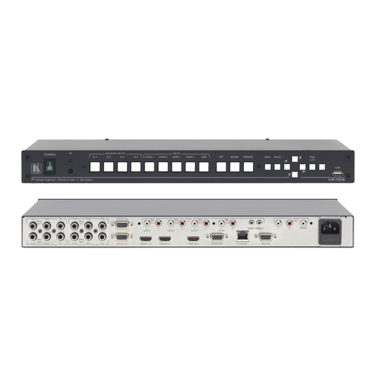
Avoid interference from neighboring electrical appliances and position your Kramer VP-729 away from moisture, excessive sunlight and dust Your Presentation Switcher / Scaler Figure 1, and Table 1 define the front panel of the VP-729; Figure 2 and Table 2 define the rear panel. KRAMER: SIMPLE CREATIVE TECHNOLOGY... -
Page 12: Table 1: Front Panel Presentation Switcher / Scaler Features
2 When selected, button illuminates. See section 7.1 for details of how to program the INPUT SELECTOR buttons 3 JPEG files in on a USB memory stick 4 Can be programmed to mute the audio signal at the same time (see Table 15) 5 Toggles between reset to XGA and reset to 720p KRAMER: SIMPLE CREATIVE TECHNOLOGY... -
Page 13: Table 2: Rear Panel Presentation Switcher / Scaler Features
Your Presentation Switcher / Scaler Table 2: Rear Panel Presentation Switcher / Scaler Features Feature Function Y/CV Connect to the video acceptor which can be either composite UNIV. IN RCA Connectors video (Y/CV), s-Video (Y/CV, P /C ) or component video (from 1 to 4) (Y/CV, P /C, P... -
Page 14: Installing In A Rack
5. The machine is earthed (grounded) in a reliable way power and is connected only to an electricity socket with If you are using a Kramer rack grounding. Pay particular attention to situations where adapter kit (for a machine that is not electricity is supplied indirectly (when the power cord 19"), see the Rack Adapters user... -
Page 15: Connecting Your Presentation Switcher / Scaler
1 Although this example shows only several inputs that are connected, you can connect all the inputs simultaneously 2 Switch OFF the power on each device before connecting it to your VP-729. After connecting your VP-729, switch on its power and then switch on the power on each device... -
Page 16: Figure 3: Connecting The Vp-729 Rear Panel
A PC via RS-232, see section 6.1 The ETHERNET port, see section 6.2 Figure 3: Connecting the VP-729 Rear Panel 1 We recommend that you use only the power cord that is supplied with this machine KRAMER: SIMPLE CREATIVE TECHNOLOGY... -
Page 17: Connecting A Pc
Connecting your Presentation Switcher / Scaler 6.1 Connecting a PC You can connect a PC (or other controller) to the VP-729 via the RS-232 port for remote control. To connect a PC to a VP-729 unit, using the Null-modem adapter provided... -
Page 18: Presentation Switcher / Scaler Buttons
Presentation Switcher / Scaler Buttons Presentation Switcher / Scaler Buttons The VP-729 includes the following front panel buttons: Nine INPUT selector buttons, see section 7.1 A PIP button, see section 7.2 BLANK and FREEZE buttons Six OSD buttons A RESET TO XGA/720p button A PANEL LOCK button, see section 7.3... -
Page 19: Activating The Pip Feature
Presentation Switcher / Scaler Buttons 7.2.1 Activating the PIP Feature You can activate the PIP by: Pressing the PIP button Pressing the PIP key on the infrared remote control transmitter (see section 7.4, Figure 7) Switching on the PIP functionality via the OSD Menu (see Figure 12 and Table 8) 7.2.2 Selecting the PIP Source... -
Page 20: Toggling Between The Pip And The Screen Source (Swap)
PIP source on all the video displays and the selected video source on all the graphic displays, compliant to Table 3. 1 Even if the input signal is not connected. In this case the PIP appears over a blank screen KRAMER: SIMPLE CREATIVE TECHNOLOGY... -
Page 22: Locking And Unlocking The Front Panel
7.3 Locking and Unlocking the Front Panel To prevent changing the settings accidentally or tampering with the unit via the front panel buttons, lock your VP-729. Unlocking releases the protection mechanism. When the front panel is locked, control is still available via RS-232 and/or the ETHERNET connector. -
Page 23: Figure 7: Infrared Remote Control Transmitter
Presentation Switcher / Scaler Buttons Figure 7 and Table 4 define the infrared Remote Control Transmitter: Table 4: Infrared Remote Control Transmitter Functions Function Freeze Pauses the output video Blank Toggles between a blank screen (blue or black screen) and the display POWER Cycles power Main Source... -
Page 24: Configuring The Vp-729 Via The Osd Menu Screens
Configuring the VP-729 via the OSD MENU Screens The OSD superimposes a menu on the screen from which you can configure and control each input signal on your VP-729, using the MENU, ENTER, OSD buttons on the front panel and the remote transmitter. -
Page 25: The Input Screen
Configuring the VP-729 via the OSD MENU Screens 8.1 The Input Screen Figure 9 and Table 5 define the Input screen. Figure 9: Input Screen Table 5: Input Screen Functions Setting Function Selection Default Source Select the source Input 1, Input 2, Input 3, Input 4, VGA 1, VGA 2,... -
Page 26: The Picture Screen
Configuring the VP-729 via the OSD MENU Screens 8.2 The Picture Screen The Brightness, Contrast, Color and Hue picture settings are saved individually for each input (except USB). Figure 10 and Table 6 define the Picture screen. Figure 10: Picture Screen... -
Page 27: The Output Screen
Configuring the VP-729 via the OSD MENU Screens 8.3 The Output Screen Figure 11 and Table 7 define the Output screen. Figure 11: Output Screen Table 7: Output Screen Functions Setting Function Selection/Range Default Resolution Set the resolution Native HDMI, 640x480x60Hz, 640x480x75Hz,... -
Page 28: The Pip Screen
Configuring the VP-729 via the OSD MENU Screens 8.4 The PIP Screen Figure 12 and Table 8 define the PIP screen. Figure 12: PIP Screen Table 8: PIP Screen Functions Setting Function Selection/Range Default On/Off Activate/deactivate the PIP On/Off feature... -
Page 29: The Audio Screen
Configuring the VP-729 via the OSD MENU Screens 8.5 The Audio Screen Figure 13 and Table 9 define the Audio screen. Figure 13: Audio Screen Table 9: Audio Screen Functions Setting Function Selection/Range Default Type Select the audio input type... -
Page 30: The Geometry Screen
Configuring the VP-729 via the OSD MENU Screens 8.6 The Geometry Screen Figure 14 and Table 10 define the Geometry screen, allowing the user flexibility in positioning his projector relative to the screening surface. Figure 14: Geometry Screen Table 10: Geometry Screen Functions... -
Page 31: The Setup Screen
Configuring the VP-729 via the OSD MENU Screens 8.7 The Setup Screen Figure 15 and Table 10 define the Setup screen. Figure 15: Setup Screen Table 12: Setup Screen Functions Setting Function Selection/Range Default Save Save a profile From Profile 1 to Profile 8... -
Page 32: The Slideshow Feature
Configuring the VP-729 via the OSD MENU Screens 8.7.1 The Slideshow Feature The VP-729 lets you run a slideshow via the USB input and set the slideshow speed via the slideshow feature. To prepare a slideshow: 1. Load the slideshow JPEG images to a USB memory stick. -
Page 33: Figure 17: Misc Setup Screen
Configuring the VP-729 via the OSD MENU Screens The Mode Set functions define the desired working resolution and refresh rate when the system cannot distinguish between similar resolutions and refresh rate values (see Table 13). Table 13: Mode Set Functions... -
Page 34: Table 15: Misc Functions
Configuring the VP-729 via the OSD MENU Screens Table 15: Misc Functions Setting Function Selection/Range Default Logo Choose ON for the start up logo to appear on On, Off or Custom Kramer the screen Logo OFF for it not to appear... -
Page 35: Table 16: Input Functions
Configuring the VP-729 via the OSD MENU Screens Table 16: Input Functions Setting Function Range Default Custom Input Custom Input Custom 1 to custom 4 Custom 1 Horizontal Total 1344 Horizontal sync pulse width Horizontal active start point Horizontal active region... -
Page 36: Verifying Configuration Details Via The Info Screen
Configuring the VP-729 via the OSD MENU Screens 8.8 Verifying Configuration Details via the Info Screen From the Information screen (see Figure 18), you can verify the main source, PIP source, the output resolution, the SYNC mode, as well as the firmware revision and the audio board firmware version (for example, 2.2 in Figure... -
Page 37: Using Text Overlay
Using Text Overlay The text overlay feature is accessed via the Application Program (AP) Running this AP with the PC connected to the VP-729 lets you display text over the screen, with features including text color and speed, transparency, text position and repetition. Current text overlay settings can be saved and loaded to the AP. -
Page 38: Table 18: Features And Functions Of The Textoverlay Application
Click to save the current setting 1 Or search the IP address 2 You have to select the connection type before connecting the software to the machine 3 For example, set to 2 to repeat the text twice KRAMER: SIMPLE CREATIVE TECHNOLOGY... -
Page 39: Audio Flash Memory Upgrade
Audio Flash Memory Upgrade 10 Audio Flash Memory Upgrade The VP-729 audio firmware is located in FLASH memory, which lets you upgrade to the latest Kramer firmware version in minutes! The process involves: Downloading from the Internet (see section 10.1) Connecting the PC to the AUDIO PROG. -
Page 40: Upgrading The Audio Firmware
1. Double click the desktop icon: “Shortcut to FLIP.EXE” . The Splash screen appears as follows: Figure 21: Splash Screen 2. After a few seconds, the Splash screen is replaced by the “Atmel – Flip” window: KRAMER: SIMPLE CREATIVE TECHNOLOGY... -
Page 41: Figure 22: Atmel - Flip Window
Audio Flash Memory Upgrade Figure 22: Atmel – Flip Window 3. Press the keyboard shortcut key F2 (or select the “Select” command from the Device menu, or press the integrated circuit icon in the upper right corner of the window). The “Device Selection”... -
Page 42: Figure 24: Selecting The Device Window
Audio Flash Memory Upgrade AT89C51RD2 T89C51RD2 Figure 24: Selecting the Device Window 5. Click OK and select “Load Hex” from the File menu. Figure 25: Loading the Hex KRAMER: SIMPLE CREATIVE TECHNOLOGY... -
Page 43: Figure 26: Rs-232 Window
Audio Flash Memory Upgrade 6. The Open File window opens. Select the correct HEX file that contains the updated version of the firmware for VP-729 (for example 44M_V1p2.hex) and click Open. 7. Press the keyboard shortcut key F3 (or select the “Communication / RS232”... -
Page 44: Figure 28: Atmel - Flip Window (Operation Completed)
13. Release the rear panel AUDIO PROG. button, using a small screwdriver. 14. Connect the power to the VP-729. Upon initialization, the new VP-729 audio software version shows in the Information menu (see section 8.8). 1 See also the blue progress indicator on the status bar 2 If an error message: “Not Finished”... -
Page 45: Technical Specifications
Technical Specifications 11 Technical Specifications Table 20 includes the technical specifications: Table 20: Technical Specifications of the VP-729 Presentation Switchers / Scaler INPUTS: 4 x universal Y/CV, Pb/C, Pr (composite, s-Video and component) 1 Vpp/75 on RCA connectors; 2 x UXGA on an 15-pin HD connector (VGA through UXGA) -
Page 46: Table 21: Technical Specifications Of The Rgbhv / Rgbs (Pc) / Rgsb (Pc) Input Signal
800x600 1280x1024 800x600 1280x1024 800x600 1280x1024 832x624 Mac16 1280x1024 1024x768 1400x1050 1024x768 1400x1050 1024x768 1440x900 1024x768 Mac19 1600x1200 1024x768 1680x1050 1024x800 1920x1200 1 For the most updated resolution list, go to our Web site at http://www.kramerelectronics.com KRAMER: SIMPLE CREATIVE TECHNOLOGY... -
Page 47: Table 23: Technical Specifications Of The Y/C, Video Signal
Technical Specifications Table 23: Technical Specifications of the Y/C, Video Signal NTSC, NTSC4.43, PAL, PAL-M, PAL-N, SECAM, PAL-60 Standard Table 24: Technical Specifications of the HDMI input Signal (for RGB or YUV Colorspace) Resolution Vertical Frequency (Hz) Remark 1080i YPbPr 1080i YPbPr 1080p... -
Page 48: Table 26: Technical Specifications Of The Rgbhv/Comp/Ypbpr Output Signal
Resolution Vertical Frequency (Hz) 640x480 640x480 800x600 800x600 800x600 1024x768 1024x768 1024x768 1280x720 1280x768 1280x768 1280x800 1280x1024 1280x1024 1280x1024 1366x768 1366x768 1400x1050 1400x1050 1600x1200 1600x1200 1920x1080 1920x1200 1680x1050 1080i 1080i 720p 720p 480p 576p 1080p 1080p KRAMER: SIMPLE CREATIVE TECHNOLOGY... -
Page 49: Table 27: Technical Specifications Of The Hdmi/Dvi/Rgb Output Signal
Technical Specifications Table 27: Technical Specifications of the HDMI/DVI/RGB Output Signal Resolution Vertical Frequency (Hz) 640x480 640x480 800x600 800x600 800x600 1024x768 1024x768 1024x768 1280x720 1280x768 1280x768 1280x800 1280x1024 1280x1024 1280x1024 1366x768 1366x768 1400x1050 1400x1050 1600x1200 1600x1200 1920x1080 1920x1200 1680x1050 1080i 1080i 720p 720p... -
Page 50: Vp-729 Communication Protocol
VP-729 Communication Protocol 12 VP-729 Communication Protocol Serial Configuration: Baud rate: 9600 (Bits per second) Data bits: 8bits Parity: None Stop bits: 1bit Communication confirmation: Send: CR Reply: CR> Set Command: Send: Y Control_Type Function Param CR Reply: Z Control_Type Function Param CR>... - Page 51 VP-729 Communication Protocol Control Type Function Parameter Description 0: Input 1 1: Input 2 2: Input 3 3: Input 4 4: VGA 1 Input Source 5: VGA 2 6: HDMI 1 7: HDMI 2 8: USB 0: Component 1: YC...
- Page 52 VP-729 Communication Protocol Control Type Function Parameter Description 0: Off 1: Low Picture Temporal NR 2: Medium 3: High 0: Off 1: Low Picture Mosquito NR 2: Medium 3: High 0: Off Picture Block NR 1: On 0: Off 1: Low...
- Page 53 VP-729 Communication Protocol Control Type Function Parameter Description 32: 1080p@60Hz 96: Custom1 97: Custom2 98: Custom3 99: Custom4 0: Auto 1: HDMI Output HDMI Type 2: DVI 0: Best Fit 1: Letterbox 2: Follow Output Aspect Ratio 3: Virtual Wide...
- Page 54 VP-729 Communication Protocol Control Type Function Parameter Description 1 ~ 256 PIP H-Size 1 ~ 256 PIP V-Size 0: Off PIP Frame 1: On 0: Red 1: Green PIP Frame Color 2: Blue 0: Analog Audio Input Type 1: S/PDIF...
- Page 55 VP-729 Communication Protocol Control Type Function Parameter Description 0: Profile 1 1: Profile 2 2: Profile 3 3: Profile 4 Save Setting 4: Profile 5 5: Profile 6 6: Profile 7 7: Profile 8 0: Profile 1 1: Profile 2...
- Page 56 VP-729 Communication Protocol Control Type Function Parameter Description 2: Mute 0: Freeze & Mute 1: Freeze Freeze key function 2: Mute 0: Off Freeze 1: On 0: Off Blank 1: On 0: Off Power 1: On Info Menu Down Left...
- Page 57 VP-729 Communication Protocol Control Type Function Parameter Description 28: 1280x1024 76 Sun 29: 1280x1024 85 30: 1400x1050 60 31: 1400x1050 75 32: 1600x1200 60 33: 1680x1050 60 34: 1080i 60 35: 1080i 50 36: 1080p 60 37: 1080p 50 38: 720p...
- Page 58 VP-729 Communication Protocol Control Type Function Parameter Description 13: 1024x768 60 14: 1024x768 70 15: 1024x768 75 16: 1024x768 75 Mac19 17: 1024x768 85 18: 1024x800 84 Sun 19: 1152x864 75 20: 1152x870 75 Mac21 21: 1152x900 66 Sun 22: 1152x900 76 Sun...
- Page 59 VP-729 Communication Protocol Control Type Function Parameter Description 512~3071 Advance Input Mode: HT 32~(HS-48) Advance Input Mode: HW 80~(HT-HA-12) Advance Input Mode: HS 640~1920 Advance Input Mode: HA <= (HT-92) 0: Negative polarity Advance Input Mode: HP 1: Positive polarity...
-
Page 60: Error Codes Description
VP-729 Communication Protocol Control Type Function Parameter Description 3:Custom4 0: Off Overscan 1: On 0: Seamless Switching Mode 1: Fast 0: Manual Auto Image Mode 1: Auto Slideshow Start Slideshow Stop Slideshow Pause Slideshow Next Slideshow Previous 0: Min 1: Low... - Page 61 EXCLUSION OF DAMAGES The liability of Kramer for any effective products is limited to the repair or replacement of the product at our option. Kramer shall not be liable for: 1. Damage to other property caused by defects in this product, damages based upon inconvenience, loss of use of the product, loss of time, commercial loss;...
- Page 62 For the latest information on our products and a list of Kramer distributors, visit our Web site: www.kramerelectronics.com, where updates to this user manual may be found. We welcome your questions, comments and feedback. Safety Warning: Disconnect the unit from the power supply before opening/servicing.
Need help?
Do you have a question about the VP-729 and is the answer not in the manual?
Questions and answers