
Subscribe to Our Youtube Channel
Related Manuals for Kramer VP-729


Summary of Contents for Kramer VP-729
- Page 1 K R A ME R E LE CT R O N IC S L T D . USER MANUAL MODEL VP-729 Presentation Switcher/Scaler P/N: 2900-000362 Rev 9...
-
Page 4: Table Of Contents
Presentation Switcher / Scaler Buttons Switching an Input The PIP Button Feature Locking and Unlocking the Front Panel The Infrared Remote Control Transmitter Configuring the VP-729 via the OSD MENU Screens The Input Screen The Picture Screen The Output Screen The PIP Screen... - Page 5 Figures Figure 1: VP-729 Presentation Switcher/Scaler Front Panel Figure 2: VP-729 Presentation Switcher/Scaler Rear Panel Figure 3: Connecting to the VP-729 Rear Panel Figure 4: Crossed Cable RS-232 Connection Figure 5: Straight Cable RS-232 Connection with a Null Modem Adapter...
-
Page 6: Introduction
GROUP 7: Scan Converters and Scalers; GROUP 8: Cables and Connectors; GROUP 9: Room Connectivity; GROUP 10: Accessories and Rack Adapters and GROUP 11: Sierra Products. Congratulations on purchasing your Kramer VP-729 Presentation Switcher / Scaler, which is ideal for the following typical applications: •... -
Page 7: Getting Started
Avoid interference from neighboring electrical appliances that may adversely influence signal quality • Position your Kramer VP-729 away from moisture, excessive sunlight and dust Recycling Kramer Products The Waste Electrical and Electronic Equipment (WEEE) Directive 2002/96/EC aims to reduce the amount of WEEE sent for disposal to landfill or incineration by requiring it to be collected and recycled. -
Page 8: Overview
Overview The Kramer VP-729 is a 9-input Proscale™ Presentation Switcher / Scaler with unbalanced stereo and digital S/PDIF audio. The VP-729 scales any composite, s-Video (Y/C), component video (YUV), HDMI or computer graphics video signal, as well as JPEG files (via USB) up or down to a selectable graphics or HDTV output resolution. - Page 9 Firmware upgrade performed via the USB port • Slideshow option, letting you run a slideshow via the USB port • An OSD (On-Screen Display) – for making adjustments – that can be located anywhere on the screen VP-729 - Contents...
-
Page 10: Defining The Vp-729 Presentation Switcher/Scaler
Remotely, from the infrared remote control transmitter (with on-screen menus) • Via the Ethernet The VP-729 is housed in a 19” 1U rack mountable enclosure, with rack “ears” included and is fed from a 100-240 VAC universal switching power supply. D efining the VP-729 Presentation Switcher/Scaler 1 3 B This section defines the VP-729. -
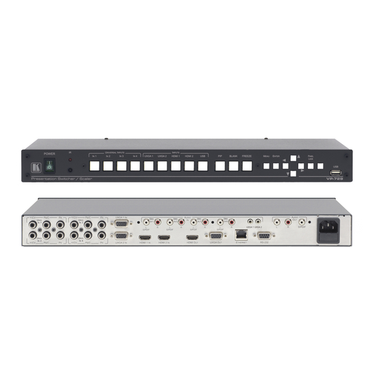
Page 11: Figure 1: Vp-729 Presentation Switcher/Scaler Front Panel
Figure 1: VP-729 Presentation Switcher/Scaler Front Panel Feature Function POWER Switch Illuminated switch for turning the machine ON or OFF IR Receiver / LED Lights red when the unit accepts IR remote commands UNIVERSAL INPUT Selector Buttons Press to select the composite video / s-Video / component video source and the appropriate audio source (from 1 to 4) -
Page 12: Figure 2: Vp-729 Presentation Switcher/Scaler Rear Panel
Connectors S/PDIF Connects to a digital audio acceptor AUDIO PROG Program Button Push to upgrade to the latest Kramer audio firmware. Release for normal operation Terminal Block Connector Connects to a PC for audio firmware upgrade HDMI 1 IN Connector... -
Page 13: Installing In A Rack
Installing in a Rack This section provides instructions for rack mounting the unit. VP-729 - Installing in a Rack... -
Page 14: Connecting The Vp-729
Connecting the VP-729 Always switch off the power to each device before connecting it to your VP-729. After connecting your VP-729, connect its power and then switch on the power to each device. To connect the VP-729 as illustrated in the example in... -
Page 15: Figure 3: Connecting To The Vp-729 Rear Panel
A PC via RS-232, (see Page The ETHERNET port, see Section 5.2 The USB connector, audio sources and acceptors, and power cord are not shown in Figure Figure 3: Connecting to the VP-729 Rear Panel VP-729 - Connecting the VP-729... -
Page 16: Connecting A Pc
Figure 5: Straight Cable RS-232 Connection with a Null Modem Adapter Connecting the VP-729 via the ETHERNET Port To connect and configure the Ethernet port of the VP-729, refer to the ETHERNET Configuration (Lantronix) GUIDE on our Web site: http://www.kramerelectronics.com. -
Page 17: Presentation Switcher / Scaler Buttons
Presentation Switcher / Scaler Buttons The VP-729 includes the following front panel buttons: • Nine INPUT selector buttons • A PIP button • BLANK and FREEZE buttons • Six OSD buttons • A RESET TO XGA/720p button • A PANEL LOCK button Switching an Input Each INPUT SELECTOR button can be used to select the source. -
Page 18: The Pip Button Feature
Press and hold the PIP front panel button while pressing the input button of the required PIP source • Press the PIP key on the IR remote control transmitter (see Section 6.4) • Access the OSD PIP menu (see Figure 13) and selecting PIP On VP-729 - Presentation Switcher / Scaler Buttons... -
Page 19: Figure 6: Pip Source Over Background
Use the buttons to select the PIP Source from the drop-down list box, and press ENTER (see Figure 13). To exit the OSD menu, press the MENU button. Figure 6: PIP Source over Background VP-729 - Presentation Switcher / Scaler Buttons... -
Page 20: Figure 7: The Swap Status
Input menu and a new PIP source through the PIP menu. Figure 7: The SWAP Status When selecting one PIP source, the VP-729 automatically recognizes and displays the selected graphic PIP source on all the video displays and the selected video... - Page 21 USB* means Yes; means No *For a USB source with the PIP enabled, the output image size is limited to 960 horizontal pixels VP-729 - Presentation Switcher / Scaler Buttons...
-
Page 22: Locking And Unlocking The Front Panel
Press the illuminated PANEL LOCK button on the front panel The front panel unlocks and the PANEL LOCK button is no longer illuminated The Save Lock and Input Lock OSD functions are defined in the table on Page VP-729 - Presentation Switcher / Scaler Buttons... -
Page 23: The Infrared Remote Control Transmitter
The Infrared Remote Control Transmitter You can control the VP-729 remotely from the infrared remote control transmitter which is powered by two AAA size 1.5V DC batteries. The IR remote control transmitter: • Has a range of up to 15 meters •... -
Page 24: Configuring The Vp-729 Via The Osd Menu Screens
The VP-729 uses an on-screen display (OSD) menu for system configuration. The menu appears as an overlay over any images that are output from the VP-729. There are eight sub-menus that are used to configure the VP-729. You can activate and navigate these menus from the front panel buttons, or from the IR remote control. -
Page 25: The Input Screen
Adjust the frequency: 0 to 50 For UXGA inputs Phase Adjust the phase: 0 to 31 Auto image Assesses the image and improves the quality accordingly, by automatically adjusting the phase, frequency and position VP-729 - Configuring the VP-729 via the OSD MENU Screens... - Page 26 2048x1536) to the route directory of a USB memory stick. Connect the Memory stick to the USB connector on the front panel. Select the USB INPUT button on the front panel. Select the desired image. VP-729 - Configuring the VP-729 via the OSD MENU Screens...
-
Page 27: The Picture Screen
If the USB input is selected, Detail Enhancement is set to Off Luma Transition Enhance Set the luminance transition enhance level: Off, Low, High Chroma Transition Enhance Set the chrominance transition enhance level: Off, Low, High VP-729 - Configuring the VP-729 via the OSD MENU Screens... -
Page 28: The Output Screen
V-Pan Vertical pan: -16 to 16 This feature is available when selecting Custom aspect ratio H-Zoom Horizontal zoom: -8 to 8 This feature is available when selecting Custom aspect ratio VP-729 - Configuring the VP-729 via the OSD MENU Screens... - Page 29 You can configure the aspect ratio of any output image to fit your application. The VP-729 offers six different aspect ratio settings: Best Fit, Letterbox, Follow Output, Virtual Wide, Follow Input, and Custom. Here is how each of these settings works.
-
Page 30: The Pip Screen
The actual range depends upon the input resolution Frame Turn the PIP frame on or off: On/Off Frame Color Select the color of the PIP frame: Red, Green or Blue Blue VP-729 - Configuring the VP-729 via the OSD MENU Screens... -
Page 31: The Audio Screen
Select the audio signal to follow the USB signal: No No Audio Audio, Input 1, Input 2, Input 3, Input 4, VGA 1, VGA 2, HDMI 1 or HDMI 2 VP-729 - Configuring the VP-729 via the OSD MENU Screens... -
Page 32: The Geometry Screen
The settings available for each application are defined in the following table: Application Available Settings Keystone Location, horizontal keystone, vertical keystone, pincushion/barrel and Reset all Anyplace Location, Diagonal Projection and Reset all Rotation Location, pincushion/barrel, Rotation and Reset all VP-729 - Configuring the VP-729 via the OSD MENU Screens... -
Page 33: The Setup Screen
Mode switching which is faster but may cause glitches on the output (applies when switching between analog inputs) Factory Select Yes to reset your VP-729 to its preset default settings Reset Advanced Opens the advanced setup menu screen (see Figure... - Page 34 HDCP signal if required (for example, when working with a Mac computer) 7.7.1 The Slideshow Feature The VP-729 lets you run a slideshow via the USB input and set the slideshow speed via the slideshow feature. To prepare a slideshow: Load the slideshow JPEG images to a USB memory stick.
-
Page 35: The Advanced Setup Screen
Set the location of Center, Top Left, Top Center Position the OSD menu Right, Bottom Left, Bottom Right Time Out Set the OSD menu 5, 10, 20, 30, 60, 90 or (sec) timeout VP-729 - Configuring the VP-729 via the OSD MENU Screens... -
Page 36: Figure 18: Misc Screen
3. The PIP must be off in order to use the capture feature The machine prompts “Cannot Capture with PIP” If PIP is on VP-729 - Configuring the VP-729 via the OSD MENU Screens... - Page 37 This ensures smooth switching, regardless of the input Overscan Select On or Off Set to On to Allow stretching of the outputted picture This feature is enabled only for HD input resolutions VP-729 - Configuring the VP-729 via the OSD MENU Screens...
-
Page 38: Figure 19: Input Functions
Horizontal polarity Vertical Total Vertical sync pulse width Vertical active start point Vertical active region Vertical polarity OCLK Output clock Enable Set to On to enable parameter change Save Apply settings VP-729 - Configuring the VP-729 via the OSD MENU Screens... -
Page 39: Figure 20: Output Functions
Reads the EDID file from the acceptor that is connected to the HDMI output. The EDID is stored as a custom output resolution. This allows automatic handling of LED screens that support very low non-standard resolutions VP-729 - Configuring the VP-729 via the OSD MENU Screens... -
Page 40: The Info Screen
(for example, 2.9 in Figure 22): Figure 22: Information Screen When the output resolution is 1920x1080 or 1920x1200, “No Embedded Audio” will appear in brackets next to the resolution. VP-729 - Configuring the VP-729 via the OSD MENU Screens... -
Page 41: Using Text Overlay
Using Text Overlay The text overlay feature is accessed via the Application Program (AP). Running this AP with the PC connected to the VP-729 lets you display text over the screen, with features including text color and speed, transparency, text position and repetition. - Page 42 Click to display the text on screen Stop Button Click to stop scrolling on screen Quit Button Click to quit the program Load Setting Button Click to load a previously saved setting Save Setting Button Click to save the current setting VP-729 - Using Text Overlay...
-
Page 43: Audio Flash Memory Upgrade
Audio Flash Memory Upgrade The VP-729 audio firmware is located in FLASH memory, which lets you upgrade to the latest Kramer firmware version in minutes! Upgrade should be carried out by skilled technical personnel. Failure to upgrade correctly will result in the malfunction of the machine The process involves: •... -
Page 44: Connecting The Pc To The Rs-232 Port
Connecting the PC to the RS-232 Port Before installing the latest Kramer audio firmware version on a VP-729 unit, do the following: Connect the PC to the AUDIO PROG. terminal block connector, as defined below: RS-232 PINOUT Connect this PIN on... -
Page 45: Figure 25: Atmel - Flip Window
Device menu, or press the integrated circuit icon in the upper right corner of the window). The “Device Selection” window appears: Figure 26: Device Selection Window Click the button next to the name of the device and select from the list: AT89C51RD2: VP-729 - Audio Flash Memory Upgrade... -
Page 46: Figure 27: Selecting The Device Window
AT89C51RD2 T89C51RD2 Figure 27: Selecting the Device Window Click OK and select “Load Hex” from the File menu. Figure 28: Loading the Hex VP-729 - Audio Flash Memory Upgrade... -
Page 47: Figure 29: Rs-232 Window
The Open File window opens. Select the correct HEX file that contains the updated version of the firmware for VP-729 (for example 44M_V1p2.hex) and click Open. Press the keyboard shortcut key F3 (or select the “Communication / RS232” command from the Settings menu, or press the keys: Alt SCR). -
Page 48: Figure 31: Atmel - Flip Window (Operation Completed)
13. If required, disconnect the rear panel AUDIO PROG. terminal block connector on the VP-729. 14. Release the rear panel AUDIO PROG. button, using a small screwdriver. 15. Connect the power to the VP-729. Upon initialization, the new VP-729 audio software version shows in the Information menu (see Figure 22). -
Page 49: Technical Specifications
Null-modem adapter, rack “ears”, IR remote control, 2 sets of C-SF/2RVM-0.5 cables, power cord, control application program via RS-232 (PC) and via Ethernet (i-Phone® and PC) Specifications are subject to change without notice For the most updated resolution list, go to our Web site at http://www.kramerelectronics.com VP-729 - Technical Specifications... - Page 50 640x480 1280x720 640x480 1280x800 720x400 1280x960 720x400 1280x960 800x600 1280x768 800x600 1280x1024 800x600 1280x1024 800x600 1280x1024 800x600 1280x1024 832x624 Mac16 1366x768 1024x768 1400x1050 1024x768 1400x1050 1024x768 1440x900 1024x768 Mac19 1600x1200 1024x768 1680x1050 1024x800 1920x1080 1152x864 1920x1200 VP-729 - Technical Specifications...
- Page 51 576i YPbPr 576p YPbPr Technical Specifications of the Component Input Signal Resolution Vertical Frequency (Hz) Remark 1080i YPbPr 1080i YPbPr 1080p YPbPr 1080p YPbPr 720p YPbPr 720p YPbPr 480i YPbPr 480p YPbPr 576i YPbPr 576p YPbPr VP-729 - Technical Specifications...
- Page 52 1280x720 1280x768 1280x768 1280x800 1280x1024 1280x1024 1280x1024 1366x768 1366x768 1400x1050 1400x1050 1600x1200 1600x1200 1920x1080 1920x1200 1680x1050 1080i 1080i 720p 720p 480p 576p 1080p 1080p 480p 59.94 720p 59.94 1080i 59.94 1080p 23.98 1080p 29.97 1080p 59.94 VP-729 - Technical Specifications...
- Page 53 1280x768 1280x768 1280x800 1280x1024 1280x1024 1280x1024 1366x768 1366x768 1400x1050 1400x1050 1600x1200 1600x1200 1920x1080 1920x1200 1680x1050 1080i 1080i 720p 720p 480p 576p 1080p 1080p 1080p 480p 59.94 720p 59.94 1080i 59.94 1080p 23.98 1080p 29.97 1080p 59.94 VP-729 - Technical Specifications...
-
Page 54: Vp-729 Communication Protocol
Example: get current Input 1 Source Type Send: Y10CR Reply: Z100CR > Definition: : ASCII Code 0x20 CR: Ascii Code 0x0D Go to our Web site at http://www.kramerelectronics.com to check for the latest VP-729 communication protocol. VP-729 - VP-729 Communication Protocol... - Page 55 Picture Color 0~360 Picture Hue 0~100 Picture Sharpness 0: Gamma 1 1: Gamma 2 2: Gamma 3 Picture Output Gamma 3: Gamma 4 4: Gamma 5 0: Auto 1: Video Picture Film Mode 2: Film VP-729 - VP-729 Communication Protocol...
- Page 56 14: 1280x1024@60Hz 15: 1280x1024@75Hz Output Resolution 16: 1366x768@50Hz 17: 1366x768@60Hz 18: 1400x1050@50Hz 19: 1400x1050@60Hz 20: 1600x1200@50Hz 21: 1600x1200@60Hz 22: 1680x1050@60Hz 23: 1920x1080@60Hz 24: 1920x1200@60Hz 25: 480p@60Hz 26: 576p@60Hz 27: 720p@50Hz 28: 720p@60Hz 29: 1080i@50Hz 30: 1080i@60Hz VP-729 - VP-729 Communication Protocol...
- Page 57 1: On 0: Picture-In-Picture 1: Picture + Picture PIP Type 2: Split 0: Input 1 1: Input 2 2: Input 3 PIP Source 3: Input 4 4: VGA 1 5: VGA 2 6: HDMI 1 VP-729 - VP-729 Communication Protocol...
- Page 58 1: Ceiling Geometry Location 2: Rear 3: Rear ceiling -40 ~ 40 Geometry Horizontal Keystone -30~30 Geometry Vertical Keystone -2000~2000 Geometry Diagonal Projection – Top Left H -2000~2000 Geometry Diagonal Projection – Top Left V VP-729 - VP-729 Communication Protocol...
- Page 59 3: Bottom Left 4: Bottom Right 0: 5 sec 1: 10 sec 2: 20 sec 3: 30 sec OSD Time Out 4: 60 sec 5: 90 sec 6: Off 0: Off 1: On Logo 2: Custom VP-729 - VP-729 Communication Protocol...
- Page 60 2: 640x480 72 3: 640x480 75 4: 640x480 85 5: 720x400 70 6: 720x400 85 Main Input status 7: 800x600 56 8: 800x600 60 9: 800x600 72 10: 800x600 75 11: 800x600 85 12: 832x624 75 Mac16 VP-729 - VP-729 Communication Protocol...
- Page 61 48: 1080p 24 49: 1280x800 60 50: 1440x900 60 51: 1440x900 60(Reduced blanking) 52: 1280x768_60 (Reduced blanking) 53: 1680x1050 60(Reduce blank) 54: 1366x768 60 55: 1366x768_60 (Reduce blank) 94: Custom1 95: Custom2 96: Custom3 97: Custom4 VP-729 - VP-729 Communication Protocol...
- Page 62 30: 1400x1050 60 31: 1400x1050 75 32: 1600x1200 60 33: 1680x1050 60 34: 1080i 60 35: 1080i 50 36: 1080p 60 37: 1080p 50 38: 720p 60 39: 720p 50 40: 480i 41: 480p 42: 576i VP-729 - VP-729 Communication Protocol...
- Page 63 Advance Input Mode: VP 1: Positive polarity 25 < OCLK < 165 Advance Input Mode: OCLK(Integer) 25 < OCLK < 165 Advance Input Mode: OCLK(Decimal) 0: Off Advance Input Mode: Enable 1: On Advance Input Mode: Save VP-729 - VP-729 Communication Protocol...
- Page 64 1: On 0: Seamless Switching Mode 1: Fast 0: Manual Auto Image Mode 1: Auto Slideshow Start Slideshow Stop Slideshow Pause Slideshow Next Slideshow Previous 0: Min 1: Low 2: Mid Slideshow 3: Long 4: Max VP-729 - VP-729 Communication Protocol...
-
Page 65: Error Codes Description
ERR 1 Unknown command ERR 2 Unknown function ERR 3 Unavailable function ERR 4 Unknown control type ERR 5 Unavailable get function ERR 6 Unavailable set function ERR 7 Unavailable parameter ERR 8 Too few arguments VP-729 - VP-729 Communication Protocol... - Page 66 VP-729 - VP-729 Communication Protocol...
- Page 67 For the latest information on our products and a list of Kramer distributors, visit our Web site where updates to this user manual may be found. We welcome your questions, comments, and feedback. Web site: www.kramerelectronics.com E-mail: info@kramerel.com SAFETY WARNING...
Need help?
Do you have a question about the VP-729 and is the answer not in the manual?
Questions and answers