Table of Contents
Advertisement
Quick Links
Download this manual
See also:
User Manual
Advertisement
Table of Contents

Subscribe to Our Youtube Channel
Related Manuals for Kramer VP-747


Summary of Contents for Kramer VP-747
- Page 1 Kramer Electronics, Ltd. USER MANUAL Model: VP-747 Universal Presentation Matrix Switcher / Scaler...
-
Page 2: Table Of Contents
Introduction About the VP-747 Getting Started Quick Start Overview About HDMI Your VP-747 Universal Presentation Matrix Switcher / Scaler Installing on a Rack Connecting the VP-747 Connecting Different Source Types Connecting the Outputs Connecting the VP-747 Control Ports Connecting a PC (via RS-232) - Page 3 Figure 19: Remote Transmitter Figure 20: VP-747 Control Application Screen Tables Table 1: Front Panel VP-747 Universal Presentation Matrix Switcher / Scaler Features Table 2: Rear Panel VP-747 Universal Presentation Matrix Switcher / Scaler Features Table 3: Connecting the Different Source Types...
-
Page 4: Introduction
GROUP 10: Accessories and Rack Adapters; GROUP 11: Sierra Products 2 The HDMI connector connects to a DVD source via the Kramer ADC DM/HF adapter 3 We recommend that you use only the power cord that is supplied with the machine 4 Download up-to-date Kramer user manuals from the Internet at this URL: http://www.kramerelectronics.com... -
Page 5: Quick Start
Getting Started 2.1 Quick Start This quick start chart summarizes the basic steps when connecting a VP-747: KRAMER: SIMPLE CREATIVE TECHNOLOGY... -
Page 6: Overview
2 Sometimes called YUV, or Y, B-Y, R-Y, or Y, Pb, Pr. The component input type (HDTV or YCbCr) may be set as HD or SD 3 The HDMI connector connects to a DVD source via the Kramer ADC DM/HF adapter... - Page 7 3 See Section 8.5 4 The direction of the wipe may be selected by the user. The speed of each transition can be adjusted 5 Processing amplification enables adjustment of different video and audio signal parameters KRAMER: SIMPLE CREATIVE TECHNOLOGY...
-
Page 8: About Hdmi
It delivers the highest high-definition image and sound quality. Note that Kramer Electronics Limited is an HDMI Adopter and an HDCP Licensee. In particular, HDMI • Provides a simple... -
Page 9: Your Vp-747 Universal Presentation Matrix Switcher / Scaler
(often associated with low quality cables) • Avoiding interference from neighboring electrical appliances, making sure not to block the ventilation holes, and positioning your VP-747 away from moisture, excessive sunlight and dust Your VP-747 Universal Presentation Matrix Switcher / Scaler... -
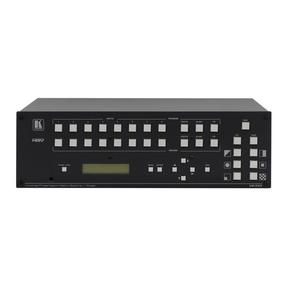
Page 10: Figure 1: Vp-747 Universal Presentation Matrix Switcher / Scaler Front Panel
Your VP-747 Universal Presentation Matrix Switcher / Scaler Figure 1: VP-747 Universal Presentation Matrix Switcher / Scaler Front Panel... -
Page 11: Table 1: Front Panel Vp-747 Universal Presentation Matrix Switcher / Scaler Features
Your VP-747 Universal Presentation Matrix Switcher / Scaler Table 1: Front Panel VP-747 Universal Presentation Matrix Switcher / Scaler Features Feature Function 1 IR Receiver / LED Green when ON; red when OFF INPUTS Selects the video source (from 1 to 8) -
Page 12: Figure 2: Vp-747 Universal Presentation Matrix Switcher / Scaler Rear Panel
Your VP-747 Universal Presentation Matrix Switcher / Scaler Figure 2: VP-747 Universal Presentation Matrix Switcher / Scaler Rear Panel... -
Page 13: Table 2: Rear Panel Vp-747 Universal Presentation Matrix Switcher / Scaler Features
3 Using a DVI/HDMI adapter or the Kramer C-HDMI/DVI HDMI to DVI Single Link (18 +1 pin) cable 4 Made up of the Y on the G/Y/CV connector together with the C on the B/Pb/C connector... -
Page 14: Installing On A Rack
5. The machine is earthed (grounded) in a reliable way power and is connected only to an electricity socket with • If you are using a Kramer rack grounding. Pay particular attention to situations where adapter kit (for a machine that is not electricity is supplied indirectly (when the power cord 19"), see the Rack Adapters user... -
Page 15: Connecting The Vp-747
, see Section 7.4 1 Switch OFF the power on each device before connecting it to your VP-747. After connecting your VP-747, switch on its power and then switch on the power on each device 2 We recommend that you use only the power cord that is supplied with this machine... -
Page 16: Figure 3: Connecting The Vp-747
Connecting the VP-747 Figure 3: Connecting the VP-747... -
Page 17: Connecting Different Source Types
Connecting the VP-747 6.1 Connecting Different Source Types As the VP-747 is universal, you can connect any type (format) of video to the inputs. Figure 4 Table 3 show an example of how to connect eight sources to the rear panel of the VP-747: an RGBHV source, an HDMI source, a CV source, a Y/C source, a component video source, an HDTV source, an RGBCs source and an RGB source. -
Page 18: Connecting The Outputs
Connecting the VP-747 6.2 Connecting the Outputs Figure 5 illustrates an example of the different connection types available for the Preview and Program outputs: For PROGRAM OUT, connect the: • R/PR, G/Y, B/PB, (PR, Y, PB) BNC OUTPUT connectors to the YUV acceptor, for example, a projector •... -
Page 19: Connecting The Vp-747 Control Ports
• ETHERNET port, see Section 7.4 7.1 Connecting a PC (via RS-232) You can connect a PC (or other controller) to the VP-747 via the RS-232 port for remote control. To connect a PC to a VP-747 unit, using the Null-modem adapter provided with the machine (recommended): •... -
Page 20: Connecting The Audio Control Port
• Connect the “A” (+) PIN on the AUDIO CONTROL RS-485 rear panel port of the VP-747 to the A (+) PIN on the RS-485 rear panel port of the VP-727A unit • Connect the “B” (-) PIN on the AUDIO CONTROL RS-485 rear panel... -
Page 21: Connecting The Vp-747 To The Kramer Vp-727T
• Connect the “A” PIN on the TO CONTROLLER mini XLR connector of the VP-747 to the A (+) PIN on the RS-485 rear panel port of the VP-727T unit • Connect the “B” (-) PIN on the TO CONTROLLER mini XLR connector... -
Page 22: Connecting The Vp-747 Via The Ethernet Port
7.4 Connecting the VP-747 via the ETHERNET port To connect the VP-747 via the ETHERNET port, do the following: Connect the ETHERNET port of the VP-747 to the LAN port of your PC, via a crossover cable with RJ-45 connectors. - Page 23 Understanding the VP-747 Using the PREVIEW output, you can: • See how the scaled output will look before displaying live during a presentation. As the example in Figure 9 illustrates, after seeing how the RGB source looks when scaled to HDMI, it can be interchanged with the YUV source, seamlessly, using an elaborate (in this case chessboard) transition effect •...
-
Page 24: Figure 9: Example Showing The Use Of The Preview And Program Output
Understanding the VP-747 Figure 9: Example showing the use of the PREVIEW and PROGRAM Output... -
Page 25: The Transition From Preview To Program
1 As selected via the Transition OSD Menu, see Section 9.1.2 2 Swap mode is the default for the VP-747 3 Composite video, s-Video, component video (sometimes called YUV or Y, B-Y, R-Y or Y, Pb, Pr ), RGB/YUV, RGBS,... -
Page 26: Understanding The Pip Button Feature
Understanding the VP-747 8.4 Understanding the PIP Button Feature The Picture-in-Picture inserter (PIP) is used for the simultaneous display of video and graphic sources , and lets you display an inserted video PIP source over a graphic source , or an inserted graphic PIP source over a video source... -
Page 27: Locking And Unlocking The Front Panel
8.5 Locking and Unlocking the Front Panel To prevent changing the settings accidentally or tampering with the unit via the front panel buttons, lock your VP-747. Unlocking releases the protection mechanism. When the front panel is locked, control is still available via RS-232, the ETHERNET, and/or the CONTROL connector. -
Page 28: Operating The Vp-747
The OSD superimposes a menu on the Preview screen from which you can control your VP-747. When the OSD front panel button is on, pressing the MENU button on the front panel or the Menu key on the infrared remote control transmitter displays the first OSD screen , the “Preview Setting”... -
Page 29: Table 5: Preview And Program Setting Osd Menus
Operating the VP-747 Table 5: Preview and Program Setting OSD Menus Setting Function Selection/Range Default Input Sub-menu Source Select the input source Channel 1 to 8 Channel 1 Type Set the video type RGBHV, RGBS RGBHV (PC/Video), RGsB (PC/Video), YCbCr, Y/C or... - Page 30 Operating the VP-747 Setting Function Selection/Range Default Scale Aspect Ratio Set the aspect ratio Best Fit , Letterbox, Best fit Follow Output , Virtual Wide, Follow Input Custom H-Pan Horizontal pan -16 to 16 V-Pan Vertical pan -16 to 16...
- Page 31 Operating the VP-747 Setting Function Selection/Range Default Output 640x480x60Hz, 640x480x75Hz, 1024x768x 800x600x50Hz, 800x600x60Hz, 60Hz 800x600x75Hz, 832x624x60Hz, 852x480x60Hz, 1024x768x50Hz, 1024x768x60Hz, 1024x768x75Hz, 1280x768x50Hz, 1280x768x60Hz, 1280x720x60Hz, 1280x800x60Hz, 1280x1024x50Hz, 1280x1024x60Hz, 1280x1024x75Hz, 1366x768x50Hz, Resolution 1366x768x60Hz, 1400x1050x50Hz, 1400x1050x60Hz, 1440x900x60Hz, 1600x1200x50Hz, 1600x1200x60Hz, 1680x1050x60Hz, 1920x1080x50Hz, 1920x1080x60Hz, 1920x1200x60Hz, 480px60Hz, 576px60Hz, 720px50Hz,...
-
Page 32: Preview And Program Input And Output Settings
Operating the VP-747 9.1.1.1 Preview and Program Input and Output Settings Figure 12 Table 6 define the input Mode Setting: Figure 12: Input Mode Setting Screen Table 6: Input Mode Functions Setting Function Range Default Custom Input Set custom values... -
Page 33: Figure 13: Output Mode Setting Screen
Operating the VP-747 Figure 13 Table 7 define the output Mode Setting: Figure 13: Output Mode Setting Screen Table 7: Output Mode Functions Setting Function Range Default Custom Output Set custom values Custom 1 to 4 Horizontal total 1344 Horizontal sync pulse width... -
Page 34: The Transition Menu Items
0 to 4 Effect Option Diagonal: Top Left Wipe: Left to Right Circle: Square Corner Bottom Left Chessboard Take Pressing causes the transition from preview to program (SWAP or FOLLOW) 1 When using the VP-747 together with the T-bar controller... -
Page 35: The Audio Menu Items
1 If the resolutions of Preview and Program are different, pressing the TAKE button when in the Freeze mode, will disable the Freeze mode 2 Download up-to-date Kramer user manuals from the Internet at this URL: http://www.kramerelectronics.com 3 Sets the pipeline delay of the audio (to compensate the delay in the video processing) -
Page 36: The Utility Menu Items
Operating the VP-747 9.1.4 The Utility Menu Items Figure 16 Table 10 define the screen. Figure 16: Utility Screen Table 10: Utility Screen Functions Setting Function Selection/Range Default TCP/IP Setting DHCP Off or On IP Address 192.168.1.39 Subnet Mask 255.255.255.0 Gateway 192.168.1.254... -
Page 37: Save Lock
Operating the VP-747 9.1.4.1 Save Lock The Save Lock qualifies the Panel Lock . When set to On, the status of the Panel lock is saved on power down, and then recalled when the unit is turned on again 9.1.4.2 Input Lock The Input Lock qualifies the Panel Lock . -
Page 38: Operating Via The Front Panel Lcd Display
For example, to set the time out to 60 seconds via the LCD Display, using the front panel buttons, do the following: 1. Turn the VP-747 unit ON, and press the OSD ON button (if selected). 2. Press the appropriate front panel OSD buttons (as defined in Figure 18). -
Page 39: Operating Via The Infrared Remote Control Transmitter
Operating the VP-747 9.3 Operating via the Infrared Remote Control Transmitter You can control the VP-747 remotely, from the infrared remote control transmitter (that has a range of up to 15 meters and is powered by two AAA size 1.5V DC batteries), as defined in... -
Page 40: Operating Via The Ethernet
• RS-232 communication between the PC and the VP-747, and setting the IP Address through the Com port menu in the Control Application 1 Or connect the serial port of your VP-747 to the serial port of your PC (see Section 7.1) -
Page 41: Control The Vp-747 Via The Ethernet/Serial Port
About 9.4.3 Control the VP-747 via the Ethernet/Serial Port To control the VP-747 via the Ethernet/serial port click the buttons on the virtual VP-747 front panel and/or open the Menu item and use the OSD menus. KRAMER: SIMPLE CREATIVE TECHNOLOGY... -
Page 42: Technical Specifications
10 Technical Specifications Table 13 includes the technical specifications: Table 13: Technical Specifications of the VP-747 INPUTS: 2 HDMI/DVI inputs connectors (HDMI version 1.2 and HDCP version 1.2) on DVI connectors 8 sets of universal BNC connectors: R/Pr, G/Y/CV, B/Pb/C, Hs/Cs, and Vs, each... -
Page 43: Vp-747 Communication Protocol
VP-747 Communication Protocol 11 VP-747 Communication Protocol This section includes the Communication Protocol for the VP-747: Communication Confirm: Send Reply CR> Set Command Send YControl_TypeFunctionParamCR Reply ZControl_TypeFunctionParamCR> Get Command Send YControl_TypeFunctionCR Reply ZControl_TypeFunctionParamCR> Example: set Preview Source Type of Current Channel = RGBHV Send Y0430CR... -
Page 44: Table 14: Set Commands
VP-747 Communication Protocol Table 14: Set Commands Control Type Function Param1 Param2 Param3 Param4 Description 0:Off Power 1:On 0:Off Panel Lock 1:On Take Fade Diagonal Wipe Circle Square Corner Chessboard Preview Picture 0:Off Preview Freeze 1:On 0:Off Preview Blank 1:On... - Page 45 VP-747 Communication Protocol Control Type Function Param1 Param2 Param3 Param4 Description Preview Input Main Source H-Position 1 ~ N N: unfixed, will change with Input Mode Preview Input Main Source V- Position 2 ~ N N: unfixed, will change with Input...
- Page 46 VP-747 Communication Protocol Control Type Function Param1 Param2 Param3 Param4 Description Preview Picture 0: Off Chroma 1: Low Transition 2: High Enhance 0: Best Fit 1: Letterbox 2: Follow Output Preview Scale Aspect Ratio 3: Virtual Wide 4: Follow Input...
- Page 47 VP-747 Communication Protocol Control Type Function Param1 Param2 Param3 Param4 Description 0:Red Preview PIP 1:Green Frame Color 2:Blue 0: 640x480 60Hz 1: 640x480 75Hz 2: 800x600 50Hz 3: 800x600 60Hz 4: 800x600 75Hz 5: 832x624 75Hz 6: 852x480 60Hz 7: 1024x768 50Hz...
- Page 48 VP-747 Communication Protocol Control Type Function Param1 Param2 Param3 Param4 Description Preview Input 32 ~ (HS-48) Setting User Mode HW Preview Input 80~(HT-HA-12) Setting User Mode HS Preview Input 640~1920 Setting User <= (HT-92) Mode HA Preview Input 0: -...
- Page 49 VP-747 Communication Protocol Control Type Function Param1 Param2 Param3 Param4 Description Preview Output 480 ~ 1200 Setting User Mode VA Preview Output 0: - Setting User 1: + Mode VP Preview Output 25 ~ 165 (Integer 0 ~ 999 Setting User...
- Page 50 VP-747 Communication Protocol Control Type Function Param1 Param2 Param3 Param4 Description 0: Auto 1: NTSC 2: PAL 3: PAL-M Program Input 4: PAL-N Video Standard 5: NTSC 4.43 6: SECAM 7: PAL 60 Program Input Main Source H-Position 1 ~ N...
- Page 51 VP-747 Communication Protocol Control Type Function Param1 Param2 Param3 Param4 Description 0: Off Program Picture 1: Low Detail 2: Medium Enhancement 3: High 0: Off Program Picture 1: Low Luma Transition Enhance 2: High Program Picture 0: Off Chroma 1: Low...
- Page 52 VP-747 Communication Protocol Control Type Function Param1 Param2 Param3 Param4 Description Program PIP 0 ~ 128 V-Position Program PIP 1 ~ 255 H-Size Program PIP 1 ~ 255 V-Size 0: Off Program PIP Frame 1: On 0:Red Program PIP 1:Green...
- Page 53 VP-747 Communication Protocol Control Type Function Param1 Param2 Param3 Param4 Description Program Yellow -100 ~ 100 Saturation 0: Custom 1 1: Custom 2 Program Custom Input Target 2: Custom 3 3: Custom 4 Program Input 512~3071 Setting User Mode HT...
- Page 54 VP-747 Communication Protocol Control Type Function Param1 Param2 Param3 Param4 Description Program Output 384~2047 Setting User Mode VT Program Output 2~(HS-13) Setting User Mode VW Program Output 15~(VT-VA-1) Setting User Mode VS Program Output 480~1200 Setting User <= (VT-16) Mode VA...
- Page 55 VP-747 Communication Protocol Control Type Function Param1 Param2 Param3 Param4 Description 0:Swap Transition Mode 1:Follow 1 ~ 5 Transition Speed 0 = no damping 1 = damping with a maximum jump size of 10 steps 2 = damping with a...
- Page 56 VP-747 Communication Protocol Control Type Function Param1 Param2 Param3 Param4 Description Audio 0: Preview headphone 1: Program source Audio Headphone -12 ~ 4 Volume, -12 = Mute -6 ~ 6 Audio Bass -6 ~ 6 Audio Treble0 -10 ~ 10...
- Page 57 VP-747 Communication Protocol Control Type Function Param1 Param2 Param3 Param4 Description 0: Off Misc Setting 1: On (Kramer) Logo 0: Off Misc Setting 1: On Save Lock 0: Off Misc Setting 1: On Input Lock 0:Blank 1:Blue Misc Setting Background...
- Page 58 EXCLUSION OF DAMAGES The liability of Kramer for any effective products is limited to the repair or replacement of the product at our option. Kramer shall not be liable for: 1. Damage to other property caused by defects in this product, damages based upon inconvenience, loss of use of the product, loss of time, commercial loss;...
- Page 59 For the latest information on our products and a list of Kramer distributors, visit our Web site: www.kramerelectronics.com, where updates to this user manual may be found. We welcome your questions, comments and feedback. Safety Warning: Disconnect the unit from the power supply before opening/servicing.
Need help?
Do you have a question about the VP-747 and is the answer not in the manual?
Questions and answers