Advertisement
Quick Links
Installation and Instruction Manual
HF
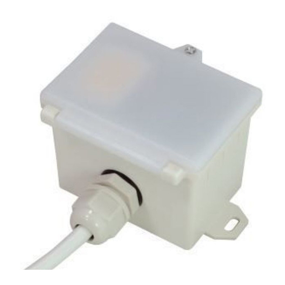
HIGH BAY RF WIRELESS MICROWAVE DALI SENSOR HMW39/RF + HC034RF
1. Technical Specifications
HMW39/RF
Product type
RF wireless microwave DALI sensor (tri-level control)
Operating voltage
120~277VAC 50/60Hz
Rated load
Maximum 20pcs DALI devices, Maximum 40mA
Power consumption
< 1.5W
o
Detection angle
360
Detection area (DxH)
10 x 12m (Maximum)
Mounting height
12m (Maximum)
Detection range
10% / 50% / 75% / 100%
Hold time
2s / 30s / 1min / 5min / 10min / 15min / 20min / 30min
Stand-by time
0s / 10s / 1min / 5min / 10min / 30min / 1h / +
Stand-by dimming level
10% / 20% / 30% / 50%
Daylight threshold
2 ~ 500Lux, Disable
RF transmission distance
30 meters in the open area
RF frequency
868MHz (FSK mode)
Warming up time
20s
o
Operating temperature
-20
C ~ +50
IP rating
IP65
HC034RF
Product type
RF wireless receiver
Operating voltage
220-240V 50Hz
Rated load
Capacitive:400W; Resistive:1200W
IP rating
IP20
3. Rotary Switch for RF grouping
commander
15 channels are available for fast grouping via rotary switch on both HMW39/RF and HC034RF.
Simply selecting the same channel on each unit, the grouping is automatically completed.
Noted:channel "0" is not for fast grouping, and sensors can only be grouped by remote control.
4. Functions
4.1 Tri-level Control (Corridor Function)
Hytronik builds this function inside the motion sensor to achieve tri-level control, for some areas
require a light change notice before switch-off.
It offers 3 levels of light: 100%-->dimmed light-->off; and 2 periods of selectable waiting time:
motion hold-time and stand-by period; Selectable daylight threshold and freedom of detection
area.
4.2 Lux Off Function
The built-in daylight sensor can read ambient natural light and switch off the fixture automatically
whenever artificial light is not required (natural light lux level exceeds daylight threshold).
Note: if the stand-by time is preset at "+∞", the fixture never switches off even when natural light
is sufficient.
o
C
receiver
2. Installation
Warnings:
1. Installation qualified engineer must be carried out by a in accordance with local
regulations.
2. Disconnect supply before installing.
3. Install to a solid surface - vibrations may cause mis-triggering.
4. Ensure environmental conditions are suitable for electronic equipment
A. Surface Mounting
Sensor module
LED indicator
Photocell
Infrared receiver
Cable entry
Rotary switch
for RF grouping
Installation rack
B. Conduit Fixing
Sensor module
LED indicator
Photocell
Infrared receiver
Rotary switch
for RF grouping
C. Clamp Fixing
Sensor module
LED indicator
Photocell
Infrared receiver
Angle adjustment
Rotary switch
for RF grouping
HC034RF (RF receiver)
RF antenna
Rotary switch
for RF grouping
1-10V+
L'
Infrared remote receiver
1-10V-
59.6
53
4.1
66.6
81.5
61.4
53
Cable entry
59.6
89.9
66.6
59.6
Luminaire clamp
53
146.6
Installation hole
71.5
78.2
87
N N L
HMW39/RF-20170510-A1
0.825"
Advertisement

Related Manuals for Hytronik HMW39/RF


Summary of Contents for Hytronik HMW39/RF
- Page 1 Rotary switch for RF grouping 15 channels are available for fast grouping via rotary switch on both HMW39/RF and HC034RF. Simply selecting the same channel on each unit, the grouping is automatically completed. Noted:channel "0" is not for fast grouping, and sensors can only be grouped by remote control.
-
Page 2: Wiring Diagram
DALI Short press “Learn/Erase” button on RC to the receiver to activate pairing mode, and the receiver unit will beep once every second for 3min. HMW39/RF Note: up to 30 units can be paired. LED indicator flash 3 times Beeper beeps rapidly beep 3 times in 1s... -
Page 3: Trouble Shooting
The fixture is on when it should not Adjust zone, change installation site or air expelled from fans, open windows Hytronik Industrial Ltd. | www.hytronik.com 3rd Floor, block C, complex building, 155#, Bai'gang road south, Bai'gang village, Xiao Jin Kou town, Huicheng district, Huizhou 516023...
Need help?
Do you have a question about the HMW39/RF and is the answer not in the manual?
Questions and answers