Table of Contents
Advertisement
Quick Links
Advertisement
Table of Contents
Troubleshooting

Related Manuals for GYROZEN 416


Summary of Contents for GYROZEN 416
- Page 1 Low Speed Centrifuge, 416 – Service manual # C01DC00304-11 1. Model: Low speed Centrifuge, 416 2. Manufacturer: Gyrozen Co., Ltd. 3. Service: BMS Co., Ltd. Technical Service Team, 82-2-3471-8171 Gyrozen Co., Ltd Customer Service Team, 82-70-8620-5350...
-
Page 2: Table Of Contents
Low Speed Centrifuge, 416 – Service manual CONFIDENTIAL Table fo Contents 1 Operating Instruction .......................4 1.1 About this manual......................4 1.2 Safety Label and safety precaution ................4 1.2.1 Safety label .......................4 1.2.2 Safety Precaution .....................5 2. Installation ...........................6 2.1 Unpacking ..........................6 2.2 Location ..........................7... - Page 3 Low Speed Centrifuge, 416 – Service manual 4.7 Imbalance sensor assembly..................... 15 4.8 RPM sensor assembly....................... 16 5. Service Mode and Adjustment .................... 17 5.1 Transition into service mode ..................17 5.2 Handling values ......................17 5.3 Procedure for Imbalance adjustment..............18 5.4 Door lock ass’y adjustment..................
-
Page 4: Operating Instruction
Low Speed Centrifuge, 416 – Service manual 1. Operating Instruction 1.1 About this manual This service manual should be used by specialized engineers authorized by Gyrozen Co., Ltd. Any repairing work operated by non-authorized personnel cannot be protected and ... -
Page 5: Safety Precaution
Supply proper voltage power according to device’s power requirement. • Let all repairing works done by authorized or qualified personnel. • Use rotors or accessories which are approved by Gyrozen. • Not try to open the lid and or move the device while the rotor is running. •... -
Page 6: Installation
Low Speed Centrifuge, 416 – Service manual 2. Installation 2.1 Unpacking 1) Check if the box contains such parts as; ① Power cable, 1ea ② Emergency door open tool, 1ea ③ User’s manual, 1ea ④ Rotor (Optional) ⑤ Rotor coupling device 2) Open the box and lift out the device carefully together with the safety padding. -
Page 7: Location
4) Install the device at the place without any kinds of corrosive gases. 2.3 Supply the power 1) 416 model uses 110V or 220V. Check proper voltage of the device and connect to adequate power outlet. 2) If the power input is more than +/- 10% of the recommended voltage or fluctuating frequently, it may affect some functions of the device. -
Page 8: Device Information
Low Speed Centrifuge, 416 – Service manual 3. Device Information 3.1 Special qualities High safety and low noise Fixed angle rotor and Swing-out Rotor available Simultaneous display of rpm and rcf speed Automatic Alarm function for Imbalance, Door open, Speed trouble ... -
Page 9: Outer Description
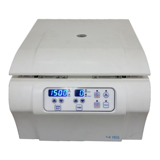
Low Speed Centrifuge, 416 – Service manual 3.3 Outer Description Angle Rotor, Swing Rotor, Main Body GRA-S-15-16 GRS-S-50-4 Swing Rotor, GRS-S-mw-2 3.4 Operating Function of Control Panel 1) RPM/RCF: to show the RPM/RCF display 2) TIME: to show pre-set time up to 99 min 59 sec (00: continuous) 3) SOFT START &... -
Page 10: Operating System
Low Speed Centrifuge, 416 – Service manual 3.5 Operating System Main board 1) DSPIC 30F4011, MICOM; It controls all devices. 2) SMPS; distributes inlet power to each part as appropriate form. 3) Inverter; transforms the single phase power to the 3 phase for running the AC induction motor. -
Page 11: Main Controller Board
3.6 Main Controller Board 3.7 Display Controller Board... -
Page 12: Disassembling
4. Disassembling 4.1 Front panel and controller board 1) Remove the 2 ea of screws at the front part of the bottom plate. 2) Detach the front panel with pushing the front panel upward. 3) Detach all of the connector.(be sure to make a mark of position) 4) Remove 6 ea of screws at the main board bracket. -
Page 13: Door Assembly
4.2 Door Assembly Remove the 2 ea of M6x10 screws at the hinge part of the door assy. Detach the door assy from the device. If needed, the 2 hinges can be detached. 4.3 Motor cover & Chamber 1) Detach the motor cover. 2) Detach the Chamber. -
Page 14: Door Lock Assembly
4.4 Door Lock Assembly 1) Detach the connectors of solenoid and door sensor from the main board. 2) Remove 4ea of M5x10 screws at the door lock assembly 3) If needed, door sensor or solenoid can be replaced. 4) Apply grease to the blue circled area for its durability. 4.5 Motor assembly <Ver 1>... -
Page 15: Anti-Vibration Rubber
4.6 Anti-vibration rubber 1) Remove 3 ea of nuts from the motor bracket. 2) Detach the motor bracket. 3) If needed, detach the anti-vibration rubber assy to replace them. 4.7 Imbalance sensor assembly <Ver 1> <Ver 2>... -
Page 16: Rpm Sensor Assembly
1) Remove the 2 ea of screws. 2) Detach the imbalance sensor assy. 3) Remove the 4 ea of screws. 4) Detach the imbalance sensor (Hall sensor). 5) In the case of adjusting the imbalance sensor, refer to 5.3 4.8 RPM sensor assembly 1) Detach 2 ea of screws at the bottom of the motor assy. -
Page 17: Service Mode And Adjustment
5. Service Mode and Adjustment 5.1 Transition into service mode On the Control panel 1) Power ON while pushing the RPM key and TIME key at the same time 2) When beep sounds push the UP( ) key and push the DOWN( ) key of left side(RPM) until “Set Window”... -
Page 18: Procedure For Imbalance Adjustment
5.3 Procedure for Imbalance adjustment 1) Press ▲ or ▼ above RPM/RCF until the number of right side becomes “8” as the picture below. Displayed Value(176) means HALL i.e. the physical distance status of the hall sensor. The normal value of imbalance sensor lies between 180 and 190. If it lies ... -
Page 19: Door Lock Ass'y Adjustment
5.4 Door lock ass’y adjustment By some reason when the door does not fit, so it does not open or close normally, the Door lock ass’y can be adjusted.(position moved). 1) Detach the front panel. 2) Loosen the 4 screws fixing the Door lock.(red circle) 3) Reposition the Door lock 4) Fasten the screws. -
Page 20: Error Code And Troubleshooting
6. Error code and Troubleshooting 6.1 Error code In the event of a malfunction, an error message with code number appears indicating the possible causes and the device is forced to stop. Turn off the power immediately, identify the causes and follow the corrective actions as recommended below. Error Problem Possible Cause/Co... - Page 21 If some trouble of firmware is confirmed; • Update the firmware • Device is not positioned on a flat, level, and vibration free surface • Relocate instrument to a flat, level, and vibration free Corrective Action surface. • Rotor is loaded with samples not evenly weighted symmetrically •...
-
Page 22: Troubleshooting
6.2 Troubleshooting If other malfunctions without error code indication occur, turn off the power immediately. Then identify the causes and carry out the corrective action as indicated below. If the device stops due to the error indication, it cannot be restarted until error is cleared. After the problem is fixed, restart the device to check if the error occurs again. -
Page 23: Maintenance
7. Maintenace 7.1 Cleaning and disinfection 1) Outer part of device ① Clean the outside of the device with a dry soft cloth. If necessary, dip the cloth with neutral detergents and clean contaminated parts. Keep dry completely after cleaning. ②... -
Page 24: Device Test For Centrifuge
7.2 Device test for centrifuge 7.2.1 Validation of actual RPM 1. Prepare a RPM speed tachometer (hand tachometer) and fluorescent light tape. 2. Attach some fluorescent light tape on a grip of a rotor lid. 3. Set the specific rpm and start the operation. 4. -
Page 25: Parts Information
8. Parts Information 8.1 Assembly Drawing 1) All parts... - Page 26 2) Top & Bottom Case...
- Page 27 3) Front Panel & Door lock...
- Page 28 4) Door...
- Page 29 5) Motor...
-
Page 30: Part List
* The grey colored letters are old version parts. Part No. Name Remark C04DR90100-00 Door Ass'y C99DR00420-03 Center window C01DR00120-04 Door(TOP) - 416 C01DR05023-00 Hinge spring (Left) - 416 An instrument requires C02DR04420-01 Hinge pin 2ea. An instrument requires C02DR00623-01 Hinge 2ea. An instrument requires C02RB01720-00 Hinge rubber 2ea. - Page 31 Motor Assembly (220V) - 416 C01MT80100-01 Motor Assembly (110V) - 416 62-1 C01MT80200-01 Motor Assembly (220V) - 416 C01MT80700-00 RPM sensor holder Assembly - 416 C01CS02733-06 Bracket for Motor C99RB00620-00 Magnet packing for Imbalance sensing One set is composed C01RB00120-00 Anti-vibration Damper of three dampers.
Need help?
Do you have a question about the 416 and is the answer not in the manual?
Questions and answers