Table of Contents
Advertisement
Quick Links
Advertisement
Table of Contents

Related Manuals for Icom IC-M412


Summary of Contents for Icom IC-M412
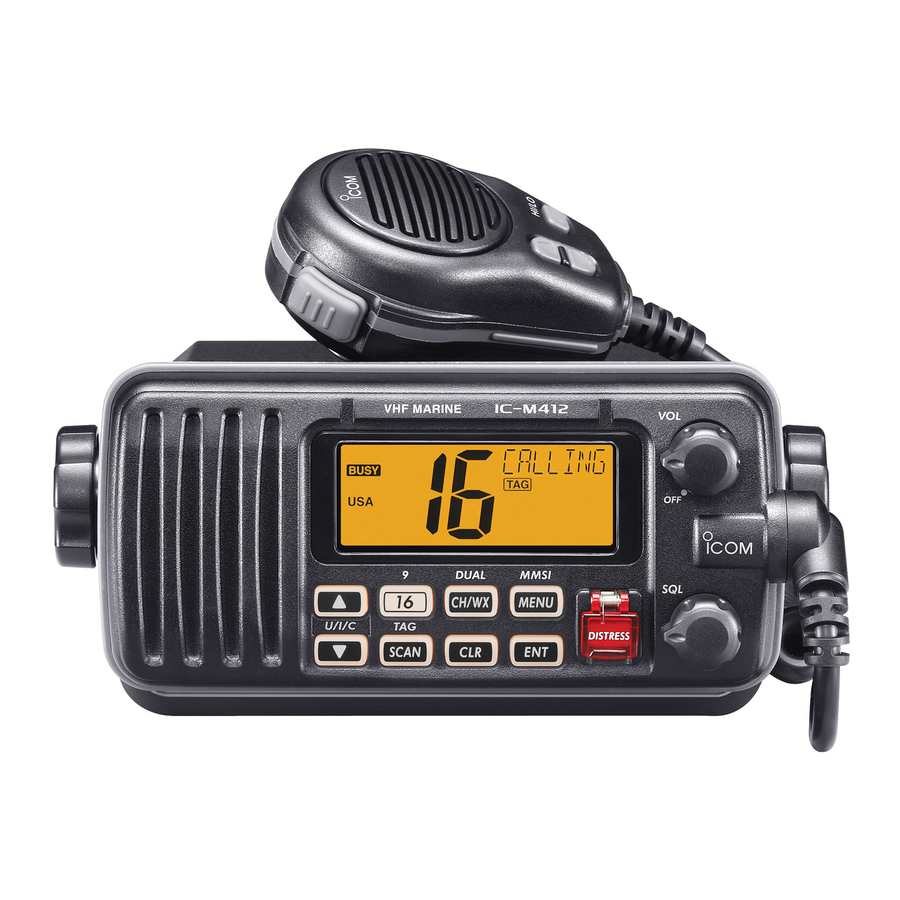
- Page 1 INSTRUCTION MANUAL VHF MARINE TRANSCEIVER iM412...
-
Page 2: Foreword
Icom, Icom Inc. and the Icom logo are registered trademarks of Icom Incor- porated (Japan) in Japan, the United States, the United Kingdom, Germany, tion. -
Page 3: In Case Of Emergency
IN CASE OF EMERGENCY NOTE A WARNING STICKER is supplied with the transceiver. If your vessel requires assistance, contact other vessels and To comply with FCC regulations, this sticker must be affixed in the Coast Guard by sending a Distress call on Channel 16. such a location as to be readily seen from the operating controls of the radio as in the diagram below. -
Page 4: Radio Operator Warning
RADIO OPERATOR WARNING Icom requires the radio operator to meet the FAILURE TO OBSERVE THESE LIMITS MAY ALLOW FCC Requirements for Radio Frequency THOSE WITHIN THE MPE RADIUS TO EXPERIENCE RF Exposure. An omnidirectional antenna with RADIATION ABSORPTION WHICH EXCEEDS THE FCC gain not greater than 9 dBi must be mounted a MAXIMUM PERMISSIBLE EXPOSURE (MPE) LIMIT. -
Page 5: Table Of Contents
TABLE OF CONTENTS 6 DSC OPERATION ...............13–40 FOREWORD ..................i IMPORTANT ..................i n MMSI code programming ............13 EXPLICIT DEFINITIONS ..............i n DSC address ID ..............14 IN CASE OF EMERGENCY ............. ii n Position and time programming ..........17 NOTE ....................ii n Position indication ..............18 RADIO OPERATOR WARNING ............ -
Page 6: Precautions
3.3 ft (1 m) performance when used with an Icom transceiver. away from the ship’s navigation compass. Icom is not responsible for the destruction or damage to an DO NOT use or place the transceiver in areas with tem- Icom transceiver in the event the Icom transceiver is used peratures below –4°F (–20°C) or above +140°F (+60°C), or... -
Page 7: Operating Rules
OPERATING RULES D PRIORITIES (2) OPERATOR’S LICENSE A Restricted Radiotelephone Operator Permit is the license • Read all rules and regulations pertaining to priorities and most often held by small vessel radio operators when a radio keep an up-to-date copy handy. Safety and Distress calls is not required for safety purposes. -
Page 8: Panel Description
PANEL DESCRIPTION n Front panel y SCAN • TAG CHANNEL KEY Speaker Function display (p. 4) [SCAN] • [TAG](SCAN) (p. 11) ➥ Push to start and stop the Normal or Priority scan. ➥ Hold down for 1 second to set or clear the displayed channel as a tag (scanned) channel. -
Page 9: Microphone
PANEL DESCRIPTION n Microphone i CHANNEL 16/CALL CHANNEL KEY [16] • [9](16) ➥ Push to select Channel 16. (p. 5) Microphone ➥ Hold down for 1 second to select Call channel. (p. 5) • “CALL” appears when Call channel is selected. ➥... -
Page 10: Function Display
PANEL DESCRIPTION n Function display y DSC ICONS Indicates the DSC status. • “DSC” appears when a DSC call is received. (pp. 23, 34) • “POS REPLY” appears when a Position Reply call is received. (p. 37) u GPS INDICATOR ➥... -
Page 11: Basic Operation
BASIC OPERATION n Channel selection ï Channel 9 (Call channel) ï Channel 16 Each regular channel group has a separate leisure-use Call Channel 16 is the distress and safety channel. It is used for channel. The Call channel is monitored during Tri-watch. The establishing initial contact with a station and for emergency Call channels can be programmed (p. - Page 12 The IC-M422 has 10 weather channels. These are used for monitoring broadcasts from NOAA (National Oceanic and The IC-M412 is pre-programmed with 57 USA, 57 interna- Atmospheric Administration.) tional and 61 Canadian channels. These channel groups may be specified for the operating area.
-
Page 13: Receiving And Transmitting
BASIC OPERATION n Receiving and transmitting IMPORTANT: To maximize the readability of your trans- CAUTION: Transmitting without an antenna may dam- age the transceiver. mitted signal, pause a few seconds after holding down [PTT], hold the microphone 5 to 10 cm from your mouth q Rotate [VOL] to turn ON the power. -
Page 14: Call Channel Programming
BASIC OPERATION n Call channel programming n Channel comments Call channel is used to select Channel 9 (default), however, The channels can be labeled with a unique alphanumeric ID you can program the Call channel with your most often-used of up to 10 characters. channels in each channel group for quick recall. -
Page 15: Microphone Lock Function
• The backlight is adjustable in 4 levels and OFF. n AquaQuake water draining function [Y]/[Z] The IC-M412 uses a technology to clear water away from [HI/LO] the speaker grill: AquaQuake. AquaQuake helps drain water away from the speaker housing (water that might otherwise muffle the sound coming from the speaker). -
Page 16: Scan Operation
SCAN OPERATION n Scan types Set the TAG channels (scanned channel) before scanning. Scanning is an efficient way to locate signals quickly over a wide frequency range. The transceiver has Priority scan and Clear the TAG channels which inconveniently stop scanning, such as those for digital communication use. -
Page 17: Setting Tag Channels
SCAN OPERATION n Setting TAG channels n Starting a scan For more efficient scanning, add a desired channels as TAG Set scan type (Priority or Normal scan) and scan resume channels or clear the TAG for unwanted channels. timer in advance, using the Set mode. (p. 42) Channels that are not tagged will be skipped during scan- q Push [U/I/C] (both [Y] and [Z]) to select a desired chan- ning. -
Page 18: Dualwatch/Tri-Watch
DUALWATCH/TRI-WATCH n Description n Operation Dualwatch monitors Channel 16 while you are receiving on q Select Dualwatch or Tri-watch in the Set mode. (p. 42) another channel; Tri-watch monitors Channel 16 and the w Push [Y] or [Z] to select a desired channel. Call channel while receiving another channel. -
Page 19: Dsc Operation
DSC OPERATION n MMSI code programming i Push [ENT], then input the same MMSI code as step y The 9-digit MMSI (Maritime Mobile Service Identity: DSC self ID) code can be programmed at power ON. for the confirmation. o Push [ENT] to set the code. This function is not available when the MMSI code has •... -
Page 20: Dsc Address Id
DSC OPERATION n DSC address ID t Push [Y] or [Z] to set up to a 10-character ID name. A total of 100 DSC address IDs (9-digit) can be programmed • Push [CH/WX] or [16] to move the cursor forward or backward. and named with up to 10 characters. - Page 21 DSC OPERATION D Deleting Address ID D Programming Group ID q Push [MENU] to enter the DSC menu. q Push [MENU] to enter the DSC menu. w Push [Y] or [Z] to select “ADDRESS,” and push [ENT]. w Push [Y] or [Z] to select “ADDRESS,” push [ENT]. e Push [Y] or [Z] to select “DEL INDV ID,”...
- Page 22 DSC OPERATION D Deleting Group ID n DSC address ID D Programming Group ID (Continued) q Push [MENU] to enter the DSC menu. t Push [Y] or [Z] to set up to a 10-character ID name. w Push [Y] or [Z] to select “ADDRESS,” and push [ENT]. •...
-
Page 23: Position And Time Programming
DSC OPERATION n Position and time programming A Distress call should include the ship’s position and time r After setting the longitude data, push [ENT] to set the data. If no GPS is connected, your position and UTC (Uni- current UTC time using [s] or [t]. versal Time Coordinated) time should be input manually. -
Page 24: Position Indication
DSC OPERATION n Position indication When a GPS receiver (NMEA0183 ver. 2.0 or 3.01) is con- nected, the transceiver displays the current position data in seconds of accuracy. A NMEA0183 ver. 2.0 or 3.01 (sentence formatters RMC, GGA, GNS, GLL) compatible GPS receiver is required. Ask your dealer about suitable GPS receivers. -
Page 25: Distress Call
DSC OPERATION n Distress call A Distress call should be transmitted, if in the opinion of the Master, the ship or a person is in distress and requires im- mediate assistance. Scrolls NEVER USE THE DISTRESS CALL WHEN YOUR SHIP OR A PERSON IS NOT IN AN EMERGENCY. r After receiving the acknowledgment, reply using the mi- A DISTRESS CALL CAN BE USED ONLY WHEN crophone. - Page 26 DSC OPERATION n Distress call (Continued) D Regular call r Push [s] or [t] to set your latitude data. After setting the The nature of the Distress call should be included in the Dis- latitude data, push [ENT] to set your longitude data. tress call.
- Page 27 DSC OPERATION y Push [DISTRESS] for 3 seconds to transmit the Distress ➥A distress alert contains (default); • Nature of distress: Selected nature of the distress call. • Position data : GPS or manual input position data is held • While pushing [DISTRESS], the key backlighting is blinking. for 23.5 hrs or until the power is turned OFF.
-
Page 28: Transmitting Dsc Calls
DSC OPERATION n Transmitting DSC calls About Manual Inputting: To ensure correct operation of the DSC function, please Push [Y] or [Z] to input the 9-digit Individual ID, then make sure you set the squelch correctly. (p. 7) push [ENT]. D Transmitting an Individual call •... - Page 29 DSC OPERATION t Push [ENT] to transmit the Individual call. u When the acknowledgement is received, “DSC” appears • If Channel 70 is busy, the transceiver stands by until the chan- and “RCV ABLE ACK” or “RCV UNABLE ACK” scrolls at nel becomes clear.
- Page 30 DSC OPERATION n Transmitting DSC calls (Continued) D Transmitting an Individual acknowledgement r Push [Y] or [Z] to select the acknowledgement “ABLE” When receiving an Individual call, you can transmit an ac- or “UNABLE,” then push [ENT]. knowledgement (‘Able to comply’ or ‘Unable to comply’) by using the on screen prompts (Quick ACK.) Also, you can UNABLE •...
- Page 31 DSC OPERATION D Transmitting a Group call y After the Individual acknowledgement call has been trans- The Group call function allows you to transmit a DSC signal mitted, the specified channel (specified by the calling sta- to a specific group only. tion) is selected automatically when “ABLE”...
- Page 32 DSC OPERATION n Transmitting DSC calls D Transmitting a Group call (Continued) About Manual Inputting: t Push [ENT] to transmit the Group call. Push [Y] or [Z] to input the 8-digit Group ID, then push • If Channel 70 is busy, the transceiver stands by until the chan- [ENT].
- Page 33 DSC OPERATION D Transmitting an All Ships call r Push [Y] or [Z] to select a desired ITU channel, then Large ships use Channel 70 as their ‘listening channel.’ push [ENT]. When you want to announce a message to these ships •...
- Page 34 DSC OPERATION n Transmitting DSC calls (Continued) D Transmitting a Position Request call Transmit a Position Request call when you want to know a r After step e, Channel 70 is automatically selected and specified ship’s current position, etc. “READY” appears at the channel comment indicator. q Push [MENU] to enter the DSC menu.
- Page 35 DSC OPERATION D Transmitting a Position Reply call t After editing the position data, push [ENT] to set. Then Transmit a Position Reply call when a Position Request call is received. edit the current UTC time directly with [Y] or [Z] (p. 17), then push [ENT].
- Page 36 DSC OPERATION n Transmitting DSC calls (Continued) D Transmitting a Polling Request call r After step e, Channel 70 is automatically selected and Transmit a Polling Request call when you want to know a “READY” appears at the channel comment indicator. specific ship is in the communication area, etc.
- Page 37 DSC OPERATION D Transmitting a Polling Reply call r Push [ENT] to transmit the Polling Reply call. Transmit a Polling Reply call when a Polling Request call is received. q Push [MENU] to enter the DSC menu. w Push [Y] or [Z] to select “POLL REPLY,” then push [ENT].
- Page 38 DSC OPERATION n Transmitting DSC calls (Continued) D Test Call r After step e, Channel 70 is automatically selected and Testing on the exclusive DSC distress and safety calling “READY” appears at the channel comment indicator. channels should be avoided as much as possible by using other methods.
- Page 39 DSC OPERATION D Transmitting a Test Ack call r Push [ENT] to transmit the Test Ack call. Transmit a Test Acknowledgement call when a Test call is received. q Push [MENU] to enter the DSC menu. w Push [Y] or [Z] to select “TEST ACK,” then push [ENT]. •...
-
Page 40: Receiving Dsc Calls
DSC OPERATION n Receiving DSC calls D Receiving a Distress call D Receiving a Distress Relay call While monitoring Channel 70 and a Distress call is received: While monitoring Channel 70 and a Distress Relay is received: ➥ The emergency alarm sounds for 2 minutes. ➥... - Page 41 DSC OPERATION D Receiving an Individual call D Receiving a Group call While monitoring Channel 70 and an Individual call is received: While monitoring Channel 70 and a Group call is received: ➥ The emergency alarm or beeps sound for 2 minutes de- ➥...
- Page 42 DSC OPERATION n Receiving DSC calls (Continued) D Receiving an All Ships call D Receiving a Geographical Area call While monitoring Channel 70 and an All Ships call is received: While monitoring Channel 70 and a Geographical Area call ➥ The emergency alarm sounds for 2 minutes depending (for the area you are in) is received: on the received categories.
- Page 43 DSC OPERATION D Receiving a Position Request call D Receiving a Position Reply call While monitoring Channel 70 and a Position Request call is While monitoring Channel 70 and a Position Request Reply received: call is received: ➥ “DSC” appears and “RCV POS REQUEST” scrolls at the ➥...
- Page 44 DSC OPERATION n Receiving DSC calls (Continued) D Receiving a Test call D Auto switch function While monitoring Channel 70 and a Test call is received: By regulation, after receiving a Distress call, the transceiver ➥ “DSC” appears and “RCV TEST CALL” scrolls at the basically switches the operating channel to CH 16.
- Page 45 DSC OPERATION D Auto tune timer This is the amount of time after receiving a Distress call The action of the transceiver may differ, depending on the before the transceiver switches to CH 16. combination of the Auto Switch function and the Auto Tune timer settings.
-
Page 46: Received Messages
DSC OPERATION n Received messages The transceiver automatically stores up to 20 distress mes- t The message information scrolls. sages and 20 other messages. The messages can be used • The stored message has various information. • Push [CLR] to exit the condition. as an assistance to the logbook. - Page 47 DSC OPERATION r Push [s] or [t] to select a desired message, push [ENT]. • “ ” appears when the unread messages is selected. Scrolls t The message information scrolls. • The stored message has various information. • Push [CLR] to exit the condition. •...
-
Page 48: Automatic Acknowledgement
DSC OPERATION n Automatic acknowledgement n Offset time This item sets the automatic acknowledgement function ON This item sets the offset time from the UTC (Universal Time or OFF. Coordinated) time. When a position request or polling request call is received, transceiver automatically transmits a position request reply q Push [MENU] to enter the DSC menu. - Page 49 DSC OPERATION...
-
Page 50: Set Mode
SET MODE n Set mode programming Set mode is used to change the conditions of the trans- q Turn power OFF. w While pushing [16], turn ON the power to enter the Set mode. ceiver’s functions: Scan type, Scan resume timer, Dual/Tri- •... -
Page 51: Set Mode Items
SET MODE n Set mode items D Weather alert D Scan type A NOAA broadcast station transmits a weather alert tone The transceiver has two scan types: Normal scan and Prior- before important weather information. When the Weather ity scan. Normal scan searches all TAG channels in the se- Alert function is turned ON, the transceiver detects the alert, lected channel group. - Page 52 SET MODE D Dual/Tri-watch D LCD backlight This item can be selected as Dualwatch or Tri-watch. (p. 12) The LCD backlight brightness can be adjusted from OFF, 1 (dark) to 4 (bright.) LCD backlight is also adjustable via [SCAN•TAG] key. (p. 9) •...
- Page 53 [VOL]. The Remote ID is included in the sentence of the format for Select the time period for the beep emission from 2, 5, 8, 10 the Icom own NMEA. (seconds) or OFF. Scrolls Remote ID 14 (default)
-
Page 54: Connections And Maintenance
CONNECTIONS AND MAINTENANCE n Connections t NMEA OUT LEAD (White) Connects to a PC or navigation equipment (NMEA0183 ver. 3.01 sentence formatters DSC, DSE compatible) for plotting position data received from other ships. CAUTION: After connecting the DC power cable, NMEA IN/OUT leads, external speaker lead (and clone lead), cover the connector and leads with a rubber vulcanzing tape as shown below, to prevent water seeping into the... -
Page 55: Antenna
CONNECTIONS AND MAINTENANCE n Antenna n Supplied accessories A key element in the performance of any communication The following accessories are supplied; system is the antenna. Ask your dealer about antennas and Mounting bracket For mounting bracket the best place to mount them. Knob bolts Flat washers (M5) n Fuse replacement... -
Page 56: Mounting The Transceiver
CONNECTIONS AND MAINTENANCE n Mounting the transceiver D Using the supplied mounting bracket EXAMPLE The universal mounting bracket supplied with your trans- ceiver allows overhead or dashboard mounting. • Mount the transceiver securely with the 2 supplied screws (5 × 20) to a surface which is more than 10 mm thick and Flat washer can support more than 5 kg. -
Page 57: Optional Mb-69 Installation
CONNECTIONS AND MAINTENANCE n Optional MB-69 installation e Attach the clamps on either side of the transceiver with 2 An optional MB-69 is available for mounting flush mount supplied bolts (5 × 8 mm). the transceiver to a flat surface such as an instrument panel. •... -
Page 58: Troubleshooting
TROUBLESHOOTING PROBLEM POSSIBLE CAUSE SOLUTION REF. The transceiver does • Bad connection to the power supply. • Check the connection to the transceiver. p. 44 not turn ON. No sound from speaker. • Squelch level is too high. • Set [SQL] to the threshold point. p. -
Page 59: Specifications And Option
SPECIFICATIONS AND OPTION n Specifications D Transmitter D General • RF output power : 25 W (High)/1 W (Low) • Frequency coverage : Tx 156.025–157.425 MHz • Modulation system : Variable reactance frequency Rx 156.050–163.275 MHz modulation • Mode : FM (16K0G3E), •... - Page 60 SPECIFICATIONS AND OPTION D Dimensions Unit: mm 28.3 111.2 14.2...
- Page 61 SPECIFICATIONS AND OPTION n Option • MB-69 flush mount kit For mounting the transceiver to a panel.
-
Page 62: Channel List
CHANNEL LIST Channel number Frequency (MHz) Channel number Frequency (MHz) Channel number Frequency (MHz) Channel number Frequency (MHz) CAN Transmit Receive CAN Transmit Receive CAN Transmit Receive CAN Transmit Receive 156.050 160.650 19A 156.950 156.950 64A 156.225 156.225 83A 157.175 157.175 156.050 156.050 157.000 161.600 156.275 160.875... -
Page 63: Template
NOTE: The solid line is the line to use when cutting into the dash/helm. The dotted line shows the outline of the IC-M412’s front panel once the radio is fitted into the hole. Do not follow the dotted line when making the hole in your dash/helm. - Page 65 MEMO...
- Page 66 A-6865?-1US Printed in Japan 2010 Icom Inc. © 1-1-32 Kamiminami, Hirano-ku, Osaka 547-0003, Japan Printed on recycled paper with soy ink.
Need help?
Do you have a question about the IC-M412 and is the answer not in the manual?
Questions and answers