Advertisement
Quick Links
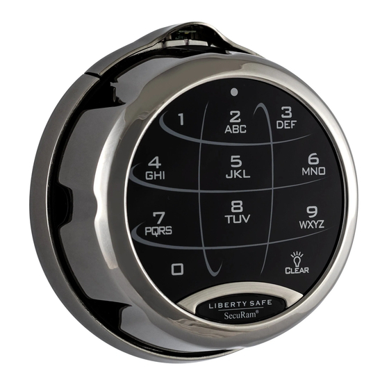
SafeLogic Xtreme Installation and Operation Instructions
SafeLogic Xtreme - Electromechanical Redundant Safe Lock System - Instructions
Please visit the website below by scanning the QR code with your smartphone or by typing in the
address below for video instructions on SafeLogic Xtreme Install Instructions.
Important:
1. Do not remove the back cover of the lock case.
2. Modifications of the lock are not recommended and will void product warranty.
3. Use a brand new 9V ALKLINE battery only. Recommend batteries: Energizer
brand.
4. Note that the 4-wire cable connectors have lock-tabs attached to ensure that the cable is
securely connected and locked into place. To prevent damage to this connector, it is required
to pinch the lock-tab when disconnecting the 4-wire cable connector from the socket.
5. Package consists of:
SecuRam Systems Inc.
http://goo.gl/3pZ16W
Doc. No. XU-EC1501A-X151123
TM
or Duracell
Page 1
TM
Advertisement

Related Manuals for Securam SafeLogic Xtreme


Summary of Contents for Securam SafeLogic Xtreme
- Page 1 SafeLogic Xtreme Installation and Operation Instructions Doc. No. XU-EC1501A-X151123 SafeLogic Xtreme - Electromechanical Redundant Safe Lock System - Instructions Please visit the website below by scanning the QR code with your smartphone or by typing in the address below for video instructions on SafeLogic Xtreme Install Instructions.
- Page 2 7. DialRing Mounting Bolt: 4 PCS. Used to install the EntryPad to the front of the safe door. 8. Clear Plastic Spindle Tube IMPORTANT: Do NOT use power tools to install the SafeLogic Xtreme. 1.0 Preparing to Install the DialRing and EntryPad Separate the DialRing from the EntryPad: Step 1: Pull up on the SpinDial release to disengage the electronics.
- Page 3 SafeLogic Xtreme Installation and Operation Instructions Doc. No. XU-EC1501A-X151123 the 6 o’clock position on the EntryPad. Step 3: Loosen the screw to disconnect the EntryPad from the DialRing. Step 4: Remove the EntryPad from the DialRing by pulling the EntryPad away from the DialRing.
- Page 4 SafeLogic Xtreme Installation and Operation Instructions Doc. No. XU-EC1501A-X151123 The mounting hole at the bottom of the DialRing is covered by the rotating dial. First pull up on the Spin Dial Release then turn the dial to expose the mounting hole and install the DialRing Mounting bolt (Part# M4 Bolt).
- Page 5 SafeLogic Xtreme Installation and Operation Instructions Doc. No. XU-EC1501A-X151123 Step 3: Use the three lock mounting bolts provided to fasten the lock body to the mounting plate. Run the cable through the channel provided on the lock body as pictured below. Ensure the cable is not crimped or folded against itself under the lock as you prepare to fasten the lock body to the mounting plate.
- Page 6 SafeLogic Xtreme Installation and Operation Instructions Doc. No. XU-EC1501A-X151123 Step 2: Take note of the 3 ports (holes) surrounding the spindle insertion point on the lock cover as pictured below. These “Locator Ports” will be used to position the cam inside the lock correctly for SpinDial access.
- Page 7 SafeLogic Xtreme Installation and Operation Instructions Doc. No. XU-EC1501A-X151123 Step 5: Now that the cam is oriented correctly, remove the spindle (Part# MSP-15A-6IN). Step 6: The spindle (Part# MSP-15A-6IN) has one end that is drill and tapped to receive the Spindle Bolt (Part# M4*16).
- Page 8 SafeLogic Xtreme Installation and Operation Instructions Doc. No. XU-EC1501A-X151123 c. IMPORTANT: Double check to make sure that the Dial Ring is locked down at “00” and that the small Phillips head screws are aligned correctly with the Locator Ports. Step 9: Mark the spindle length flush to the lock cover.
- Page 9 SafeLogic Xtreme Installation and Operation Instructions Doc. No. XU-EC1501A-X151123 Step 15: IMPORTANT: Now from the Lock body side, tighten the small Phillips head screws to lock the spindle into place at the cam. 5.0 Check the Installation of the DialRing Step 1: Pull up on the SpinDial release, so the dial can now be rotated.
- Page 10 SafeLogic Xtreme Installation and Operation Instructions Doc. No. XU-EC1501A-X151123 Step 1: Install the 9V ALKALINE battery in the back of the EntryPad. Embossed in the bottom of battery compartment you will see the battery orientation markings: “+” and “-“. Install the battery with the correct orientation as indicated by the “+”...
- Page 11 SafeLogic Xtreme Installation and Operation Instructions Doc. No. XU-EC1501A-X151123 Step 4: Tighten the EntryPad screw as seen below. Step 5: Now rotate the SpinDial back to “00” and lock down the SpinDial release. 7.0 Test after installation ALWAYS PERFORM THE TEST WITH THE SAFE DOOR OPEN.
- Page 12 (Fig. 7) and close the SpinDial release. (Fig. 8) 8.0 Electronic Lock Operating Instructions The SafeLogic Xtreme comes with the user code set to the factory default of 1-2-3-4-5-6. 8.1 To Open the Lock with a Code Step 1: Press 1-2-3-4-5-6.
- Page 13 SafeLogic Xtreme Installation and Operation Instructions Doc. No. XU-EC1501A-X151123 9.1 First SpinDial Combination Opening Step 1: Pull up on the SpinDial Release to disengage the electronics Step 2: Now rotate the SpinDial 4 full revolutions to the left (or counter clockwise) stop when you see 50 at the Dialing Index the fourth time.
-
Page 14: Change Index
SafeLogic Xtreme Installation and Operation Instructions Doc. No. XU-EC1501A-X151123 VERY IMPORTANT: The last number of your new combination cannot be set between 95 and 99 or between 0 and 20 - this is called the “Forbidden Zone”. If the last number is set within the Forbidden Zone, it will cause a condition that prevents the mechanism from operating correctly. - Page 15 SafeLogic Xtreme Installation and Operation Instructions Doc. No. XU-EC1501A-X151123 lock case. You may have to wiggle the change key to get it to engage all 3 wheels. You will know that the key is fully inserted when the Change Key tab is fully inside the lock case.
- Page 16 SafeLogic Xtreme Installation and Operation Instructions Doc. No. XU-EC1501A-X151123 Step 15: Commit the new combination to memory. 9.3 Opening with a Mechanical Combination For this example, we will assume the combination is set to 53-23-67 Step 1: Pull up on the SpinDial Release to disengage the electronics Step 2: Now rotate the SpinDial 4 full revolutions to the left (or counter clockwise) stop when you see 53, the first number in our combination, at the Dialing Index the fourth time.
- Page 17 SafeLogic Xtreme Installation and Operation Instructions Doc. No. XU-EC1501A-X151123 Step 1: Disconnect the 4-wire cable from the lock. Step 2: Insert a U-type tool (paper clip or other) into the Reset holes and slide through the inner holes also. Step 3: Connect the EntryPad to the DialRing and reconnect the cable to the lock.
Need help?
Do you have a question about the SafeLogic Xtreme and is the answer not in the manual?
Questions and answers