Subscribe to Our Youtube Channel
Summary of Contents for Hirschmann PAT TRS 05 / PATB3
- Page 1 TRS 05 / PATB3 (A2B only) INSTALLATION / SETUP MANUAL P/N 190203 Revision – 03/09/2006...
-
Page 3: Table Of Contents
Installation NOTICE Hirschmann makes no warranty of any kind with regard to this material, including, but not limited to, the implied warranties of merchantability and/or its fitness for a particular purpose. Hirschmann will not be liable for errors contained in this manual or for incidental or consequential damages in connection with the furnishing, performance, or use of this manual. -
Page 4: Installation
For jib installations, locate the switch close to the jib head. Remove the lynch pin from the standoff. Slide the A2B switch onto the standoff. Replace the lynch pin into the standoff. Install the weight and chain onto the A2B switch. © Hirschmann Rev. -03/09/2006 190203_-... -
Page 5: Receiver Mounting
The TRS 05 receiver will mount in the same place as the A2B receiver. Attach the 13ft long antenna base and whip to the TRS 05; and mount the magnetic antenna parallel to the ground, as shown below. © Hirschmann Rev. -03/09/2006 190203_-... -
Page 6: System Description
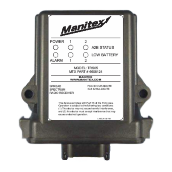
Sensor #2 batteries are low and need replaced. Note that the sensor is still operating correctly. Green Heartbeat LED This will flash during normal operation. If it is a solid or off, the receiver has a software error or the board has a component failure. © Hirschmann Rev. -03/09/2006 190203_-... -
Page 7: Control Identification
Heartbeat LED: When blinking, this small surface board mounted green LED indicates the system is operation properly. ID button: The red ID button, located below the software chip on the receiver board, is used to setup the sensor transmitter to the receiver. © Hirschmann Rev. -03/09/2006 190203_-... -
Page 8: Operation
Use any off-the-shelf alkaline C-cells; Duracell, Eveready, etc. After replacing the transmitter batteries, the receiver should clear the low battery indication. ALARM LED This LED will light simultaneously with the engaging of the lock out solenoids (if installed). © Hirschmann Rev. -03/09/2006 190203_-... -
Page 9: Setup A Sensor/Menu Options
Green LED 1 Blinking: Search for / Install sensor 1. LED will turn solid when the sensor is found. NOTE: A new sensor or transmitter maybe install over an existing link, when this occurs the previous link and code are removed from memory and the new one stored. © Hirschmann Rev. -03/09/2006 190203_-... -
Page 10: Uninstall Sensor / Transmitter
LED 1 Install/setup sensor on channel 2 blinking green LED 2 Uninstall a sensor on channel 1 solid LED 1 Uninstall a sensor on channel 2 solid LED 2 Exit/No action LEDs off no action © Hirschmann Rev. -03/09/2006 190203_-... -
Page 11: Spare Part Numbers
Spare Part Numbers SPARE PART NUMBERS 031-300-050-671 ANTENNA, 918 MHz FOR TRS05 ASSEMBLY 060-576 WHIP ELEMENT 031-300-050-672 ANTENNA, 918 MHz MAGNETICBASE 13' long wire 6608124 RADIO, RECEIVER, TRS05-2 SPREAD SPECTRUM 6600918 CABLE ASSY, 10’ 4-COND. © Hirschmann Rev. -03/09/2006 190203_-... - Page 12 FOR TRS05ASSEMBLY 060-576 WHIP MHz MAGNETICBASE 13ft long wire ELEMENT 031-300-050-688 ANTENNA, 918 MHz RCL 90° 031-300-060-559 ANTENNA ASSY, 918 MHz WHIP FORLOAD CELL 031-300-050-535 CONNECTOR, SMA RIGHT ANGLE M/FREVERSE POLARITY 6608125 A2B Switch 031-300-050-763 Neoprene rubber gasket © Hirschmann Rev. -03/09/2006 190203_-...


Need help?
Do you have a question about the PAT TRS 05 / PATB3 and is the answer not in the manual?
Questions and answers