Sign In
Upload
Download
Table of Contents
Contents
Add to my manuals
Delete from my manuals
Share
URL of this page:
HTML Link:
Bookmark this page
Add
Manual will be automatically added to "My Manuals"
Print this page
×
Bookmark added
×
Added to my manuals
Manuals
Brands
Hirschmann Manuals
Switch
RSPE30
User manual
Hirschmann RSPE30 User Manual
Industrial ethernet rail switch power
Hide thumbs
1
2
Table Of Contents
3
4
5
6
7
8
9
10
11
12
13
14
15
16
17
18
19
20
21
22
23
24
25
26
27
28
29
30
31
32
33
34
35
36
37
38
39
40
41
42
43
44
45
46
47
48
49
50
51
52
53
54
55
56
57
58
59
60
61
62
63
64
65
66
67
68
69
70
71
72
73
74
page
of
74
Go
/
74
Contents
Table of Contents
Bookmarks
Table of Contents
Table of Contents
Safety Instructions
About this Manual
Key
1 Description
General Description
Device Name and Product Code
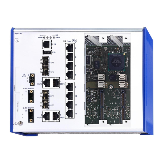
Device Views
Front View
Rear View
Power Supply
Supply Voltage with the Characteristic Value K9
Supply Voltage with the Characteristic Value KK
Supply Voltage with the Characteristic Value CC
Supply Voltage with the Characteristic Value PP
Ethernet Ports
10/100 Mbit/S Twisted Pair Port
Gigabit Combo Port
100 Mbit/S F/O Port (Optional)
Support of Poe(+)
Display Elements
Device State
Media Module Status
Port Status
Management Interfaces
Interface (External Management)
SD Card Interface
USB Interface
Signal Contact
Checking the Package Contents
Installing the SD Card (Optional)
Mounting a Cover Panel or a Media Module
Mounting a Cover Panel
Mounting a Media Module
Installing and Grounding the Device
Installing the Device Onto the DIN Rail
Grounding the Device
Installing an SFP Transceiver (Optional)
Connecting the Terminal Blocks
Supply Voltage with the Characteristic Value K9
Supply Voltage with the Characteristic Value KK
Supply Voltage with the Characteristic Value CC
Supply Voltage with the Characteristic Value PP
Signal Contact
Operating the Device
Connecting Data Cables
Filling out the Inscription Label
3 Making Basic Settings
4 Monitoring the Ambient Air Temperature
5 Maintenance and Service
6 Disassembly
Removing the Device
Removing an SFP Transceiver (Optional)
Removing a Media Module (Optional)
7 Technical Data
General Technical Data
Dimension Drawings
EMC and Immunity
Network Range
Power Consumption/Power Output
Scope of Delivery, Order Numbers and Accessories
Installation RSPE30/32/35/37
Advertisement
Quick Links
1
General Description
2
Front View
3
Ethernet Ports
4
Making Basic Settings
Download this manual
User Manual
Installation
Industrial Ethernet Rail Switch Power
RSPE30/32/35/37
Installation RSPE30/32/35/37
Technical support
Release 16 04/2019
https://hirschmann-support.belden.com
Table of
Contents
Previous
Page
Next
Page
1
2
3
4
5
Advertisement
Table of Contents
Need help?
Do you have a question about the RSPE30 and is the answer not in the manual?
Ask a question
Questions and answers
Subscribe to Our Youtube Channel
Related Manuals for Hirschmann RSPE30
Switch Hirschmann RSP 20 User Manual
Industrial ethernet rail switch power (52 pages)
Switch Hirschmann RSPL 20 User Manual
Industrial ethernet rail switch power lite (54 pages)
Switch Hirschmann RSP 25 User Manual
Industrial ethernet rail switch power (66 pages)
Switch Hirschmann RSPE 30 User Manual
Industrial ethernet rail switch power enhanced (68 pages)
Switch Hirschmann RSPM20-4Z64Z6 Series User Manual
Rail switch power media module (40 pages)
Switch Hirschmann RSP 30 User Manual
Industrial ethernet rail switch power (66 pages)
Switch Hirschmann RSP 35 User Manual
Industrial ethernet rail switch power (66 pages)
Switch Hirschmann RSPE35 User Manual
Industrial ethernet rail switch power (74 pages)
Switch Hirschmann RSPE37 User Manual
Industrial ethernet rail switch power (74 pages)
Switch Hirschmann RS20 User Manual
Industrial (284 pages)
Switch Hirschmann RS20 series User Manual
Industrial ethernet rail switch (80 pages)
Switch Hirschmann RS20 Reference Manual
Industrial ethernet switch web-based interface (108 pages)
Switch Hirschmann RS20 User Manual
Redundancy configuration industrial ethernet (gigabit) switch (100 pages)
Switch Hirschmann RS20 Reference Manual
Ethernet gigabit switch (572 pages)
Switch Hirschmann RS20 User Manual
(294 pages)
Switch Hirschmann RS2-4R Description And Operating Instructions
Industrial ethernet rail switch 2 (10 pages)
This manual is also suitable for:
Rspe35
Rspe32
Rspe37
Table of Contents
Save PDF
Print
Rename the bookmark
Delete bookmark?
Delete from my manuals?
Login
Sign In
OR
Sign in with Facebook
Sign in with Google
Upload manual
Upload from disk
Upload from URL


Need help?
Do you have a question about the RSPE30 and is the answer not in the manual?
Questions and answers