
Related Manuals for Hirschmann RSP 20


Summary of Contents for Hirschmann RSP 20
-
Page 1: User Manual
User Manual Installation Industrial Ethernet Rail Switch Power RSP 20/25/30/35 Installation RSP 20/25/30/35 Technical support Release 08 08/2014 https://hirschmann-support.belden.eu.com... - Page 2 In addition, we refer to the conditions of use specified in the license contract. You can get the latest version of this manual on the Internet at the Hirschmann product site (www.hirschmann.com). Printed in Germany Hirschmann Automation and Control GmbH Stuttgarter Str.
-
Page 3: Table Of Contents
Checking the package contents Installing the SD card (optional) Installing and grounding the device 2.3.1 Installing the device onto the DIN rail 2.3.2 Grounding the device Installing an SFP transceiver (optional) Connecting the terminal blocks Installation RSP 20/25/30/35 Release 08 08/2014... - Page 4 Connecting data cables Filling out the inscription label Making basic settings Upgrading Software Monitoring the ambient air temperature Maintenance and service Disassembly Removing the device Removing an SFP transceiver (optional) Technical data Further Support Installation RSP 20/25/30/35 Release 08 08/2014...
-
Page 5: Safety Instructions
Never start operation with damaged components. The device does not contain any service components. If the device is not functioning correctly, or if it is damaged, turn off the power supply and return the device to Hirschmann for inspection. WARNING UNCONTROLLED MACHINE ACTIONS To avoid uncontrolled machine actions caused by data loss, configure all the data transmission devices individually. - Page 6 Regarding the properties of this fuse: See “General technical data” on page 40. Supply with AC voltage: The wire diameter of the power supply cable is at least 0.75 mm² (North America: AWG18) on the working voltage input. Installation RSP 20/25/30/35 Release 08 08/2014...
- Page 7 The wire diameter of the power supply cable is at least 1 mm² (North America: AWG16) on the working voltage input. The cross-section of the ground conductor is the same size as or bigger than the cross-section of the power supply cables. Installation RSP 20/25/30/35 Release 08 08/2014...
-
Page 8: Installation Site Requirements
K9 or KK: See “Device name and product code” on page 13. Install this device solely in a switch cabinet or in an operating site with restricted access, to which maintenance staff have exclusive access. Installation RSP 20/25/30/35 Release 08 08/2014... - Page 9 In accordance with the above-named EU directive(s), the EU conformity declaration will be at the disposal of the relevant authorities at the following address: Hirschmann Automation and Control GmbH Stuttgarter Str. 45-51 72654 Neckartenzlingen Germany Tel.: +49 1805 141538...
- Page 10 Recycling note After usage, this device must be disposed of properly as electronic waste, in accordance with the current disposal regulations of your county, state, and country. Installation RSP 20/25/30/35 Release 08 08/2014...
-
Page 11: About This Manual
Event log Simultaneous configuration of multiple devices Graphical user interface with network layout SNMP/OPC gateway The symbols used in this manual have the following meanings: Listing Work step Subheading Installation RSP 20/25/30/35 Release 08 08/2014... -
Page 12: Description
Certifications Redundancy functions The RSP 20/25/30/35 devices are designed for the special requirements of industrial automation. They meet the relevant industry standards, provide very high operational reliability, even under extreme conditions, and also long-term reliability and flexibility. The devices work without a fan. -
Page 13: Device Name And Product Code
2 voltage inputs for redundant power supply Rated voltage range AC 110 V ... 230 V, 50 Hz ... 60 Hz Rated voltage range DC 60 V ... 250 V Table 1: Device name and product code Installation RSP 20/25/30/35 Release 08 08/2014... - Page 14 IEEE 1613 Table 2: Assignment: application cases, certificates and declarations, character- istic values a. X = Certificate or declaration present (X) = Certificate or declaration in preparation (x) = Certificate or declaration available upon request Installation RSP 20/25/30/35 Release 08 08/2014...
- Page 15 Table 3: Sample product code RSP20-11003Z6TT-SCCZ9HSE2SXX.X.
-
Page 16: Combination Options
– S; T; E CC; K9; KK Z9; Y9; V9; VY HS 2A; 2S; 3S – 08 TT; ZT – S; T; E CC; K9; KK Z9; Y9; V9; VY HM; HP; HH E 2A; 2S; 3S Table 4: Combination options of the RSP 20/25/30/35 device variants... -
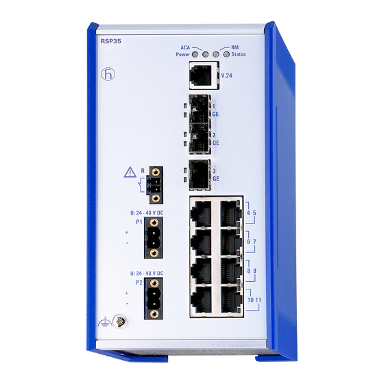
Page 17: Device Views
3-pin terminal block characteristic value: Operating voltage 2 voltage inputs for redundant power supply 3-pin terminal block characteristic value: Connection for the signal contact Table 5: Front view (using the example RSP20-11003Z6TT-SCC...) Installation RSP 20/25/30/35 Release 08 08/2014... -
Page 18: Rear View
Working voltage with the characteristic value KK For the redundant power supply of the device, two 3-pin terminal blocks are available. For further information see “Working voltage with the characteristic value KK” on page Installation RSP 20/25/30/35 Release 08 08/2014... -
Page 19: Working Voltage Characteristic Value Cc
The socket housing is electrically connected with the front panel. Function Receive path RD− Receive path Transmission path TD− Transmission path 4,5,7,8 — Table 6: Pin assignment of the 10/100 Mbit/ twisted pair port, RJ-45 socket, MDI-X mode Installation RSP 20/25/30/35 Release 08 08/2014... -
Page 20: 100/1000 Mbit/S Twisted Pair Port (Optional)
100 Mbit/s half-duplex mode, 100 Mbit/s full duplex mode State on delivery: 100 Mbit/s full duplex when using a Fast Ethernet SFP transceiver 1000 Mbit/s full duplex when using a Gigabit Ethernet SFP transceiver Installation RSP 20/25/30/35 Release 08 08/2014... -
Page 21: Display Elements
Characteristics can be configured Lights up Device is inoperative Flashes 1 time The boot parameters used when the a period device has been started differ from the boot parameters saved. Start the device again. Installation RSP 20/25/30/35 Release 08 08/2014... -
Page 22: Port State
Device detects a non-supported SFP trans- ceiver or a non-supported data rate Flashing Device is transmitting and/or receiving data Flashes 1 time a period Device detects at least one unauthorized MAC address (Port Security Violation) Installation RSP 20/25/30/35 Release 08 08/2014... -
Page 23: Management Interfaces
For information about the position on the device see “Rear view” on page On the front of the device there is an LED display that informs you about the status of the interface. Only use Hirschmann SD cards. Installation RSP 20/25/30/35 Release 08 08/2014... -
Page 24: Signal Contact
The management setting specifies which events switch a contact. You can also use the management to switch the signal contact manually and thus control external devices. Installation RSP 20/25/30/35 Release 08 08/2014... -
Page 25: Installation
Deactivate the write protection on the SD card by pushing the write- protect lock towards the middle of the card. Push the SD card into the slot with the beveled corner facing upwards. Tighten the thumb screw hand-tight to fix the SD card. Installation RSP 20/25/30/35 Release 08 08/2014... -
Page 26: Installing And Grounding The Device
DIN EN 60715, proceed as follows: Slide the upper snap-in guide of the device into the DIN rail. Press the media module downwards onto the clip-in bar. Snap in the device. Installation RSP 20/25/30/35 Release 08 08/2014... -
Page 27: Grounding The Device
The device variants featuring working voltage with the characteristic value K9 and KK have 1 connection for protective grounding. The device variants with working voltage characteristic value CC have a connection for functional grounding. Ground the device via the ground screw. Installation RSP 20/25/30/35 Release 08 08/2014... -
Page 28: Installing An Sfp Transceiver (Optional)
Installing an SFP transceiver (optional) For this device, only use suitable SFP modules from Hirschmann. See “Accessories” on page 48. Proceed as follows: Remove the protective cap from the SFP transceiver. Push the SFP transceiver with the lock closed into the socket until you hear it latch in. -
Page 29: Working Voltage Characteristic Value K9
Connect the protective conductor according to the pin assignment on the device with the clamp. Connect the wires according to the pin assignment on the device with the clamps. Fasten the wires connected by tightening the terminal screws. Installation RSP 20/25/30/35 Release 08 08/2014... -
Page 30: Working Voltage With The Characteristic Value Kk
Install this device solely in a switch cabinet or in an operating site with restricted access, to which maintenance staff have exclusive access. Failure to follow these instructions can result in death, serious injury, or equipment damage. Installation RSP 20/25/30/35 Release 08 08/2014... -
Page 31: Working Voltage Characteristic Value Cc
For every working voltage to be connected, perform the following steps: Remove the power connector from the device. Connect the wires according to the pin assignment on the device with the clamps. Fasten the wires connected by tightening the terminal screws. Installation RSP 20/25/30/35 Release 08 08/2014... -
Page 32: Signal Contact
The torque for tightening the terminal block for the signal contact on the device is 3 lb-in (0.34 Nm). Proceed as follows: Use screws to secure the connectors to the device. Enable the working voltage. Installation RSP 20/25/30/35 Release 08 08/2014... -
Page 33: Connecting Data Cables
For further information see “Device name and product code” on page Filling out the inscription label The inscription label for the IP address on the front of the device helps you identify your device. Installation RSP 20/25/30/35 Release 08 08/2014... -
Page 34: Making Basic Settings
(read/write) V.24 data rate: 9,600 Baud Ethernet ports: link status is not evaluated (signal contact) Optical ports: Full duplex TP ports: Autonegotiation RSTP (Rapid Spanning Tree) activated Installation RSP 20/25/30/35 Release 08 08/2014... -
Page 35: Upgrading Software
Upgrading Software The upgrade options for your RSP 20/25/30/35 device depend on the soft- ware level of the device. See “Device name and product code” on page 13. Note: For software version 04.0 or higher, “HiOS” is available as a common software image for the software levels 2A and 3S. -
Page 36: Monitoring The Ambient Air Temperature
It is higher than the ambient air temperature. The maximum internal temperature of the device named in the technical data is a guideline that indicates to you that the maximum ambient air temperature has possibly been exceeded. Installation RSP 20/25/30/35 Release 08 08/2014... -
Page 37: Maintenance And Service
Hirschmann are continually working on improving and developing their software. Check regularly whether there is an updated version of the soft- ware that provides you with additional benefits. You find information and software downloads on the Hirschmann product pages on the Internet (www.hirschmann.com). ... -
Page 38: Disassembly
Disconnect the terminal blocks. Disconnect the grounding. Insert a screwdriver horizontally below the housing into the locking gate. Without tilting the screwdriver, pull the locking gate down and tilt the device upwards. Installation RSP 20/25/30/35 Release 08 08/2014... -
Page 39: Removing An Sfp Transceiver (Optional)
Removing an SFP transceiver (optional) Proceed as follows: Pull the SFP transceiver out of the socket by means of the opened lock. Close the SFP transceiver with the protective cap. Installation RSP 20/25/30/35 Release 08 08/2014... -
Page 40: Technical Data
General technical data Dimensions RSP 20/25/30/35 See “Dimension drawings” on page 42. W × H × D Weight RSP 20/25/30/35-..TT-S..approx. 1.2 kg RSP 20/25/30/35-..TT-T..approx. 1.5 kg RSP 20/25/30/35-..TT-E..RSP 20/25/30/35-..ZT-S..approx. 1.3 kg RSP 20/25/30/35-..ZT-T..approx. 1.6 kg RSP 20/25/30/35-..ZT-E.. - Page 41 Temperature of the ambient air at a distance of 2 inches (5 cm) from the device c. Hirschmann recommends to use SFP transceivers with the "EEC" extension. d. Use only SFP transceivers with the “EEC” extension, otherwise the standard temperature range applies.
-
Page 42: Dimension Drawings
114,7 6,55 4.52 inch 0.26 2.76 98,29 3.87 Figure 7: Dimensions of device variants with operating temperature characteristic value E and T. For the characteristic value, cf. “Device name and product code” on page Installation RSP 20/25/30/35 Release 08 08/2014... - Page 43 AC and DC supply connec- Class A Class A tions EN 61000-6-4 AC and DC supply connec- Fulfilled Fulfilled tions EN 55022 Telecommunication Class A Class A connections EN 61000-6-4 Telecommunication Fulfilled Fulfilled connections Installation RSP 20/25/30/35 Release 08 08/2014...
- Page 44 EN 61000-4-12 line/line — 1 kV IEEE C37.90.1 Damped oscillation - data line EN 61000-4-12 line/ground — 2.5 kV IEEE C37.90.1 EN 61000-4-12 line/line — 1 kV Pulse magnetic fields EN 61000-4-9 — 300 A/m Installation RSP 20/25/30/35 Release 08 08/2014...
- Page 45 LH 1590 nm 1490 nm 9/125 µm 5-24 dB 23-80 km 0.25 19 ps/(nm×km) LH/LC dB/km Table 13: F/O port (bidirectional Gigabit Ethernet SFP Transceiver) a. including 3 dB system reserve when compliance with the fiber data is observed Installation RSP 20/25/30/35 Release 08 08/2014...
- Page 46 3 dB system reserve when compliance with the fiber data is observed b. with ultra-low-loss optical fiber MM = Multimode, SM = Singlemode, LH = Singlemode Longhaul 10/100/1000 Mbit/s twisted pair port Length of a twisted pair segment max. 100 m (for cat5e cable) Installation RSP 20/25/30/35 Release 08 08/2014...
-
Page 47: Scope Of Delivery
KK) 2 × 2-pin terminal block for the working voltage (solely for device variants with the characteristic value CC for the working voltage) 1 × Installation user manual 1 × CD/DVD with manual Installation RSP 20/25/30/35 Release 08 08/2014... - Page 48 M-SFP-LX+/ LC EEC 942 024-001 M-SFP-LH/LC 943 042-001 M-SFP-LH/LC EEC 943 898-001 M-SFP-LH+/LC 943 049-001 Bidirectional Gigabit Ethernet SFP transceiver Order number M-SFP-BIDI Type A LX/LC EEC 943 974-001 M-SFP-BIDI Type B LX/LC EEC 943 974-002 Installation RSP 20/25/30/35 Release 08 08/2014...
- Page 49 943 865-001 M-FAST SFP-MM/LC EEC 943 945-001 M-FAST SFP-SM/LC 943 866-001 M-FAST SFP-SM/LC EEC 943 946-001 M-FAST SFP-SM+/LC 943 867-001 M-FAST SFP-SM+/LC EEC 943 947-001 M-FAST SFP-LH/LC 943 868-001 M-FAST SFP-LH/LC EEC 943 948-001 Installation RSP 20/25/30/35 Release 08 08/2014...
- Page 50 The device has an approval based on a specific standard or de facto stan- dard only if the approval indicator appears on the housing. The device generally fulfills the technical and industry standards named in their current versions. Installation RSP 20/25/30/35 Release 08 08/2014...
-
Page 51: A Further Support
Further Support Technical Questions For technical questions, please contact any Hirschmann dealer in your area or Hirschmann directly. You will find the addresses of our partners on the Internet at http://www.hirschmann.com Contact our support at https://hirschmann-support.belden.eu.com You can contact us in the EMEA region at ...
Need help?
Do you have a question about the RSP 20 and is the answer not in the manual?
Questions and answers