Table of Contents
Advertisement
User Manual
Installation
Industrial Ethernet Ruggedized Switch
MACH1040 family Full Gigabit
1
MAR1040
FAULT
USB
V.24
RM
Sb
R1
R2
P
2
MAR1040
1
MAR1040
FAULT
USB
V.24
RM
Sb
R1
R2
P
2
MAR1042
1
MAR1140
FAULT
USB
V.24
RM
Sb
R1
R2
P
2
MAR1140
1
MAR1142
FAULT
USB
V.24
RM
Sb
R1
R2
P
2
MAR1142
MAR1140, MAR1142
Installation MACH1040
Release 05 03/2021
3
5
7
4
6
8
P
3
5
7
4
6
8
3
5
7
4
6
8
P
3
5
7
4
6
8
9
11
13
10
12
14
9
11
13
10
12
14
9
11
13
10
12
14
9
11
13
10
12
14
P
RM Stand by
1
3
5
R1 R2
FAULT
2
4
6
https://hirschmann-support.belden.com
15
16
15
16
Relay
15
P2
R2
Relay
P1
R1
16
Relay
15
P2
R2
Relay
P1
R1
16
7
9
11
13
15
8
10
12
14
16
ETHERNET Service Port
Technical support
Advertisement
Table of Contents

Related Manuals for Hirschmann MACH1040


Summary of Contents for Hirschmann MACH1040
- Page 1 User Manual Installation Industrial Ethernet Ruggedized Switch MACH1040 family Full Gigabit MAR1040 FAULT V.24 MAR1040 MAR1040 FAULT V.24 MAR1042 Relay MAR1140 FAULT V.24 Relay MAR1140 Relay MAR1142 FAULT V.24 Relay MAR1142 RM Stand by R1 R2 FAULT ETHERNET Service Port...
- Page 2 In addition, we refer to the conditions of use specified in the license contract. You can get the latest version of this manual on the Internet at the Hirschmann product site (www.hirschmann.com). Hirschmann Automation and Control GmbH Stuttgarter Str.
-
Page 3: Table Of Contents
Wiring of the terminal blocks for supply voltage and signal contact 2.3.1 Connecting the supply voltage 2.3.2 Wiring the signal contact Installing and grounding the device 2.4.1 Mounting in a switch cabinet 2.4.2 Vertical mounting on the wall Installation MACH1040 Release 05 03/2021... - Page 4 7.4.2 Fast Ethernet SFP transceiver 7.4.3 Bidirectional Fast Ethernet SFP transceiver 7.4.4 Gigabit Ethernet SFP transceiver 7.4.5 Bidirectional Gigabit Ethernet SFP transceiver Power consumption/power output Scope of delivery Order numbers/product description Accessories Underlying technical standards Further support Installation MACH1040 Release 05 03/2021...
-
Page 5: Important Information
WARNING WARNING indicates a potentially hazardous situation which, if not avoided, could result in death or serious injury. CAUTION CAUTION indicates a possible danger which, if not avoided, may result in minor injuries. Installation MACH1040 Release 05 03/2021... - Page 6 NOTICE NOTE provides information about procedures that do not involve the risk of injury. Installation MACH1040 Release 05 03/2021...
-
Page 7: Safety Instructions
Certified usage Use the product only for the application cases described in the Hirschmann product information, including this manual. Operate the product only according to the technical specifications. See “Technical data” on page 45. Connect to the product only components suitable for the requirements of the specific application case. - Page 8 This is the prerequisite for grounding and labeling circuits, devices, and systems in accordance with current standards in safety technology. Qualified personnel are aware of the dangers that exist in their work. Installation MACH1040 Release 05 03/2021...
- Page 9 If the neutral conductor (AC) or the negative conductor (DC) is not grounded: there is a fuse in each of the two wires. The wire diameter of the power supply cable is at least 1 mm² (North America: AWG16) on the supply voltage input. Installation MACH1040 Release 05 03/2021...
- Page 10 First connect the protective conductor before connecting the wires for the supply voltage. If your device comprises a 2nd supply voltage connection of this type: First connect the protective conductor before connecting the wires for the supply voltages. Installation MACH1040 Release 05 03/2021...
- Page 11 à moins que l'emplacement soit connu pour ne contenir aucune concentration de gaz inflammable. Avertissement - Risque d'explosion - La substitution de tout composant peut rendre ce matériel incompatible pour une utilisation en classe I, division 2. Installation MACH1040 Release 05 03/2021...
- Page 12 240VAC 50/60Hz parameters Ordinary Location - Non-Hazardous Area The Use in Hazardous Locations is only allowed for MACH1040-Family model No´s which are individually labelled “FOR USE IN CLASS I, DIVISION 2 HAZARDOUS LOCATIONS” Notes: The nonincendive field wiring circuit concept allows interconnection of nonincendive field wiring apparatus and associated nonincendive field wiring apparatus using any of the wiring methods permitted for unclassified locations when certain parametric conditions are met.
- Page 13 In accordance with the above-named EU directive(s), the EU conformity declaration will be at the disposal of the relevant authorities at the following address: Hirschmann Automation and Control GmbH Stuttgarter Str. 45-51 72654 Neckartenzlingen You find the EU conformity declaration as PDF file for downloading on the Internet at: https://www.doc.hirschmann.com/certificates.html...
- Page 14 Recycling note After usage, this device must be disposed of properly as electronic waste, in accordance with the current disposal regulations of your county, state, and country. Installation MACH1040 Release 05 03/2021...
-
Page 15: About This Manual
Reference Manual Command Line Interface Router Configuration user manual The Network Management Software Industrial HiVision provides you with options for smooth configuration and monitoring. You find further information on the Internet at the Hirschmann product pages: http://www.hirschmann.com/en/QR/INET-Industrial-HiVision Installation MACH1040 Release 05 03/2021... -
Page 16: Key
The symbols used in this manual have the following meanings: Listing Work step Subheading Installation MACH1040 Release 05 03/2021... -
Page 17: Description
There are convenient options for managing the device. Manage your devices via: Web browser Telnet HiView (software for putting the device into operation) Network management software (for example Industrial HiVision) V.24 interface (locally on the device) Installation MACH1040 Release 05 03/2021... -
Page 18: Combination Options
The device provides you with a large range of functions, which the manuals for the operating software inform you about. You can download these manuals as PDF files from the Internet on the Hirschmann product pages (http://www.doc.hirschmann.com). The Hirschmann network components help you ensure continuous communication across all levels of the company. -
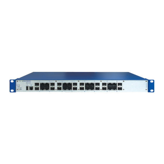
Page 19: Description Of The Device Variants
Combination options of the MACH1040 device variants Description of the device variants The MACH1040 devices are Ruggedized Switches with 16 × 1-Gigabit Ethernet ports (10/100/1000 Mbit/s, connectible alternatively with optical SFP transceivers or twisted pair cables). These ports are suitable for the connection of terminal devices or network segments according to the standards IEEE 802.3 100/1000BASE-FX (SFP slot) or IEEE 802.3... - Page 20 Description of the device variants: MAR1040-... with 16 × 1GE ports MAR1042 FAULT V.24 Relay Relay Front side of the device: MAR1042 device LED display elements USB interface V.24 interface (external management) Table 3: Description of the device variants: MAR1042-... with 16 × 1GE portsand Installation MACH1040 Release 05 03/2021...
- Page 21 Front side of the device: LED display elements device status LED display elements port status Table 4: Description of the device variants: MAR1140-... with 16 × 1GE ports, ports on the rear side of the device Installation MACH1040 Release 05 03/2021...
- Page 22 LED display elements port status LED display element service port Service port Table 5: Description of the device variants: MAR1142-... with 16 × 1GE ports and PoE, ports on the rear side of the device Installation MACH1040 Release 05 03/2021...
-
Page 23: Support Of Poe
The PoE power is supplied via the wire pairs transmitting the signal (phantom voltage). The individual ports are not electrically insulated from each other. The following conditions are met in accordance with IEEE 802.3af: Endpoint PSE Alternative A Installation MACH1040 Release 05 03/2021... -
Page 24: Gigabit Combo Port
Gigabit combo port The MACH1040 device provides 16 combo ports for transmission speeds of up to 1000 Mbit/s. You have the option of alternatively connecting a twisted pair cable via a RJ45 socket or an optical fiber via a SFP transceiver to a combo port. -
Page 25: 100/1000 Mbit/S F/O Port
Phantom supply b. Spare pair supply Display elements After the supply voltage is set up, the Software starts and initializes the device. Afterwards, the device performs a self-test. During this process, various LEDs light up. Installation MACH1040 Release 05 03/2021... -
Page 26: Device State
Display elements of the MAR1140 and MAR1142 (ports on the rear side of the device) 1.5.1 Device state FAULT RM Stand by R1 R2 FAULT MAR1140, MAR1142 MAR1040, MAR1042, MAR1140, MAR1142 These LEDs provide information about conditions which affect the operation of the whole device. Installation MACH1040 Release 05 03/2021... - Page 27 Display Color Activity Meaning FAULT Signal contact 1 lights up The signal contact is open - it is reporting a detected error. none The signal contact is closed, it is not reporting any detected errors. Installation MACH1040 Release 05 03/2021...
-
Page 28: Led Display Elements Port Status
If the manual setting is active on the signal contact “Relay”, then the error display is independent of the setting of the signal contact. 1.5.2 LED display elements port status ETHERNET Service Port MAR1040, MAR1042, MAR1140, MAR1142 MAR1140, MAR1142 Installation MACH1040 Release 05 03/2021... - Page 29 Flashing green (1 × a period) Port is switched to stand-by Flashing green (3 × a period) Port is disabled Flashing yellow Receive data/send data Table 8: LED display elements port status: link state, data Installation MACH1040 Release 05 03/2021...
-
Page 30: Management Interfaces
The manual is available for download on the Internet: https:// www.doc.hirschmann.com 1.6.2 USB interface The USB interface allows you to connect the AutoConfiguration Adapter ACA22 storage medium. This is used for saving/loading the configuration data and diagnostic information, and for loading the software. Installation MACH1040 Release 05 03/2021... -
Page 31: Signal Contact
Ring redundancy reserve is available. On delivery, there is no ring redundancy monitoring. Note: The signal contact functions are available when the power supply is connected. If a redundant power supply is present but switched off, contact interruption occurs at the associated signal contact. Installation MACH1040 Release 05 03/2021... -
Page 32: Installation
“Scope of delivery” on page Check the individual parts for transport damage. Installing an SFP transceiver (optional) Prerequisites: Exclusively use Hirschmann SFP transceivers. See “Accessories” on page 57. Figure 2: Installing SFP transceivers: Installation sequence Installation MACH1040 Release 05 03/2021... -
Page 33: Wiring Of The Terminal Blocks For Supply Voltage And Signal Contact
The signal contact is connected via a 2-pin terminal block with screw locking (1 × or 2 ×, depending on device variant). For device variants without PoE: The supply voltage in MACH1040/ MACH1140 device variants can be connected redundantly with 2 power supply units. -
Page 34: Connecting The Supply Voltage
L or M. Relay Figure 3: Power supply unit supply voltage characteristic value L, DC voltage (see on page 45 “General technical data”) Connecting 1 - Supply voltage 2 - Signal contact Installation MACH1040 Release 05 03/2021... -
Page 35: Wiring The Signal Contact
The torque for tightening the terminal block for the signal contact on the device is 3 lb-in (0.34 Nm). Note: Use copper wire with cross-section AWG 20 to AWG 12 (0.5 mm 3.0 mm ) and stripping length12 mm. Installation MACH1040 Release 05 03/2021... -
Page 36: Installing And Grounding The Device
Measure the depth of the 19" cabinet so that all the lines to be connected can be fed in easily. Assemble the sliding or mounting rails in the 19" switch cabinet as specified by the manufacturer. Installation MACH1040 Release 05 03/2021... - Page 37 Figure 5: Assembly in a switch cabinet with sliding/mounting rails 1 - MACH1040 device 2 - sliding/mounting rail 3 - 19" switch cabinet On delivery, 2 mounting brackets are mounted to the sides of the device (see figure below). Figure 6: Mounting in the switch cabinet ...
-
Page 38: Vertical Mounting On The Wall
See “Accessories” on page 57. Fasten the device by screwing the brackets to the wall. 2.4.3 Grounding the device The device is grounded via the separate grounding screw on the back of the device. Installation MACH1040 Release 05 03/2021... -
Page 39: Operating The Device
Verify that you connect LH ports only with LH ports, SX ports only with SX ports, and LX ports only with LX ports. Connect the data cables according to your requirements. See “100/1000 Mbit/s F/O port” on page 25. Installation MACH1040 Release 05 03/2021... -
Page 40: Making Basic Settings
Input via the V.24 interface Input via the HiView or Industrial HiVision application. You find further information about the applications HiView or Industrial HiVision on the Internet at the Hirschmann product pages: HiView http://www.hirschmann.com/en/QR/INET-HiView Industrial HiVision http://www.hirschmann.com/en/QR/INET-Industrial-HiVision ... -
Page 41: First Login (Password Change)
Log on to the device again with your new password. Note: If you lost your password, then use the System Monitor to reset the password. For further information see: https://hirschmann-support.belden.com/en/kb/required-password-change- new-procedure-for-first-time-login Installation MACH1040 Release 05 03/2021... -
Page 42: Monitoring The Ambient Air Temperature
It is higher than the ambient air temperature. The maximum internal temperature of the device named in the technical data is a guideline that indicates to you that the maximum ambient air temperature has possibly been exceeded. Installation MACH1040 Release 05 03/2021... -
Page 43: Maintenance And Service
Maintenance and service When designing this device, Hirschmann largely avoided using high-wear parts. The parts subject to wear and tear are dimensioned to last longer than the lifetime of the product when it is operated normally. Operate this device according to the specifications. -
Page 44: Disassembly
Open the locking mechanism of the SFP transceiver (1). Pull the SFP transceiver out of the slot via the open locking mechanism (2). Close the SFP transceiver with the protection cap (3). Installation MACH1040 Release 05 03/2021... -
Page 45: Technical Data
Signal contact Electrical parameters = 30 V (Hazardous = 90 mA Locations Class 1, = 50 pF Division 2) = 2 μH See “Use in Hazardous Locations” on page 11. Connection type 2-pin terminal block Installation MACH1040 Release 05 03/2021... - Page 46 Temperature of the ambient air at a distance of 2 in (5 cm) from the device b. If you are using SFP modules without the “EEC” extension, an operating temperature of 0 °C ... +55 °C (+32 °F ... +131 °F) (see on page 57 “Accessories”) applies to your device. Installation MACH1040 Release 05 03/2021...
-
Page 47: Dimension Drawings
Dimension drawings inch 462,6 0.13 0.13 17.38 19,3 19,3 0.76 17.48 0.76 Figure 8: Dimensions for mounting on a flat surface Installation MACH1040 Release 05 03/2021... - Page 48 462,6 0.13 17.38 0.13 inch 19,3 19,3 0.76 17.48 0.76 Figure 9: Dimensions for mounting in a switch cabinet Installation MACH1040 Release 05 03/2021...
-
Page 49: Emc And Immunity
Test level immunity IEEE 1613 EMI TYPE test, test according to IEEE C37.90.3 Electrostatic discharge Contact discharge ±8 kV Air discharge ±15 kV IEEE C37.90.2 Electromagnetic field 80 MHz ... 1000 MHz 35 V/m (peak) Installation MACH1040 Release 05 03/2021... - Page 50 Vibration, test Fc 2 - 9 Hz with 3 mm amplitude 1 g at 9 - 150 Hz 1.5 g at 200 - 500 Hz IEC 60068-2-27 Shock, test Ea 15 g at 11 ms Installation MACH1040 Release 05 03/2021...
-
Page 51: Network Range
Network range Note: The line lengths specified for the transceivers apply for the respective fiber data (fiber attenuation and Bandwidth Length Product (BLP)/ Dispersion). 7.4.1 10/100/1000 Mbit/s twisted pair port 10/100/1000 Mbit/s twisted pair port Length of a twisted pair segment max. -
Page 52: Bidirectional Fast Ethernet Sfp Transceiver
Including 3 dB system reserve when compliance with the fiber data is observed. c. With ultra-low-loss optical fiber. d. You will find further information on certifications on the Internet on the Hirschmann product pages (www.hirschmann.com). 7.4.3 Bidirectional Fast Ethernet SFP transceiver... -
Page 53: Gigabit Ethernet Sfp Transceiver
b. Including 3 dB system reserve when compliance with the fiber data is observed. 7.4.4 Gigabit Ethernet SFP transceiver Product code Mode Wave length Fiber System Example for F/O line Fiber attenuation BLP/Dispersion attenuation length M-SFP-SX/LC... 850 nm 50/125 µm 0 dB ... -
Page 54: Bidirectional Gigabit Ethernet Sfp Transceiver
Product code Mode Wave length Fiber System Example for F/O line Fiber attenuation BLP/Dispersion attenuation length M-SFP-LH+/LC EEC LH 1550 nm 9/125 µm 13 dB ... 32 dB 38.52 mi ... 85.75 mi 0.21 dB/km (typically) 19 ps/(nm×km) (62 km ... 138 km) SFP-GIG-LX/LC... - Page 55 Product code Mode Wave length Wave length Fiber System Example for F/O line Fiber BLP/Dispersion attenuation length attenuation SFP-GIG-BA LX/ 1310 nm 1550 nm 9/125 µm 0 dB ... 15 dB 0 km ... 12.43 mi 0.4 dB/km 3.5 ps/(nm×km) LC EEC (0 km ...
-
Page 56: Power Consumption/Power Output
1 × or 2 × 3-pin terminal block for the supply voltage (depending on the device variant) 1 × or 2 × 2-pin terminal block for signal contact (depending on the device variant) Table 16: Scope of delivery Installation MACH1040 Release 05 03/2021... -
Page 57: Order Numbers/Product Description
M-FAST SFP-SM/LC EEC 943 946-001 M-FAST SFP-SM+/LC 943 867-001 M-FAST SFP-SM+/LC EEC 943 947-001 M-FAST SFP-LH/LC 943 868-001 M-FAST SFP-LH/LC EEC 943 948-001 SFP-FAST-MM/LC 942 194-001 SFP-FAST-MM/LC EEC 942 194-002 Table 17: Accessory: Fast Ethernet SFP transceiver Installation MACH1040 Release 05 03/2021... - Page 58 942 195-001 SFP-FAST-SM/LC EEC 942 195-002 Table 17: Accessory: Fast Ethernet SFP transceiver a. You will find further information on certifications on the Internet on the Hirschmann product pages (www.hirschmann.com). Bidirectional Fast Ethernet SFP transceivers Order number SFP-FAST-BA MM/LC EEC...
- Page 59 SFP-GIG-BB LX+/LC EEC 942 208-002 SFP-GIG-BA LH/LC EEC 942 209-001 SFP-GIG-BB LH/LC EEC 942 209-002 a. You will find further information on certifications on the Internet on the Hirschmann product pages (www.hirschmann.com). Other accessories Order number AutoConfiguration Adapter ACA22-USB (EEC) 942 124-001...
-
Page 60: Underlying Technical Standards
If your device has a shipping approval according to Germanischer Lloyd (GL), you find the approval mark printed on the device label. You will find out whether your device has other shipping approvals on the Hirschmann website at www.hirschmann.com in the product information. -
Page 61: A Further Support
Further support Technical questions For technical questions, please contact any Hirschmann dealer in your area or Hirschmann directly. You find the addresses of our partners on the Internet at http:// www.hirschmann.com. A list of local telephone numbers and email addresses for technical support...
Need help?
Do you have a question about the MACH1040 and is the answer not in the manual?
Questions and answers