
Related Manuals for Hirschmann PowerLION-24TP


Summary of Contents for Hirschmann PowerLION-24TP
-
Page 1: Installation Guide
Installation Guide Gigabit ETHERNET Layer 3 Switch PowerLION-24TP Installation Guide PowerLION-24TP Technische Unterstützung www.edge-core.com Release 1.0 02/06 HAC-Support@hirschmann.de... - Page 2 This publication has been created by Hirschmann Automation and Control GmbH according to the best of our knowledge. Hirschmann reserves the right to change the contents of this manual without prior notice. Hirschmann can give no guarantee in respect of the correctness or accuracy of the details in this publication.
- Page 3 Installation Guide Gigabit Ethernet Switch Layer 3 Switch with 20 1000BASE-T (RJ-45) Ports, 4 Combination Ports (RJ-45/SFP), 1 Extender Module Slot, and 2 Stacking Ports...
-
Page 5: Japan Vcci Class A
Compliances and Safety Warnings FCC - Class A This equipment generates, uses, and can radiate radio frequency energy and, if not installed and used in accordance with the instruction manual, may cause interference to radio communications. It has been tested and found to comply with the limits for a Class A computing device pursuant to Subpart B of Part 15 of FCC Rules, which are designed to provide reasonable protection against such interference when operated in a commercial environment. - Page 6 CE Mark Declaration of Conformance for EMI and Safety (EEC) This information technology equipment complies with the requirements of the Council Directive 89/336/EEC on the Approximation of the laws of the Member States relating to Electromagnetic Compatibility and 73/23/EEC for electrical equipment used within certain voltage limits and the Amendment Directive 93/68/EEC.
-
Page 7: Safety Compliance
Safety Compliance Warning: Fiber Optic Port Safety When using a fiber optic port, never look at the transmit laser while it is powered on. Also, never look directly at the fiber TX port and fiber cable CLASS I LASER DEVICE ends when they are powered on. - Page 8 Power Cord Set U.S.A. and Canada The cord set must be UL-approved and CSA certified. The minimum specifications for the flexible cord are: - No. 18 AWG - not longer than 2 meters, or 16 AWG. - Type SV or SJ - 3-conductor The cord set must have a rated current capacity of at least 10 A The attachment plug must be an earth-grounding type with NEMA...
- Page 9 France et Pérou uniquement: Ce groupe ne peut pas être alimenté par un dispositif à impédance à la terre. Si vos alimentations sont du type impédance à la terre, ce groupe doit être alimenté par une tension de 230 V (2 P+T) par le biais d’un transformateur d’isolement à rapport 1:1, avec un point secondaire de connexion portant l’appellation Neutre et avec raccordement direct à...
-
Page 10: Warnings And Cautionary Messages
Stromkabel . Dies muss von dem Land, in dem es benutzt wird geprüft werden: Schweiz Dieser Stromstecker muß die SEV/ASE 1011Bestimmungen einhalt- Europe Das Netzkabel muß vom Typ HO3VVF3GO.75 (Mindestanforderung) sein und die Aufschrift <HAR> oder <BASEC> tragen. Der Netzstecker muß die Norm CEE 7/7 erfüllen (”SCHUKO”). Warnings and Cautionary Messages Warning: This product does not contain any serviceable user parts. -
Page 11: Related Publications
All printed documentation for this product uses biodegradable paper that originates from sustained and managed forests. The inks used in the printing process are non-toxic. Purpose This guide details the hardware features of the PowerLION-24TP switches, including their physical and performance-related characteristics, and how to install each switch. Audience This guide is for system administrators with a working knowledge of network management. - Page 12 viii...
-
Page 13: Table Of Contents
Contents Chapter 1: Introduction Overview Switch Architecture Network Management Options Description of Hardware 10/100/1000BASE-T Ports SFP Slots Stacking Ports Port and System Status LEDs Optional Redundant Power Unit Power Supply Sockets Optional Media Extender Module Extender Module LEDs Features and Benefits Connectivity Expandability Performance... - Page 14 Contents Installing an Optional Module into the Switch Installing an Optional SFP Transceiver Connecting Switches in a Stack Stacking Topologies Connecting to a Power Source Connecting to the Console Port Wiring Map for Serial Cable Chapter 4: Making Network Connections Connecting Network Devices Twisted-Pair Devices Cabling Guidelines...
- Page 15 Contents Appendix C: Specifications Physical Characteristics Switch Features Management Features Standards Compliances Extender Modules 10G Xenpak Extender Module (Xenpak) Installationsort Auswählen (Selecting a Site - German) Montage (Rack Mounting Instructions - German) Schaltschrank-Montage...
- Page 16 Contents Glossary Index...
- Page 17 Tables Table 1-1 Port Status LEDs Table 1-2 System Status LEDs Table 1-3 Module LEDs Table 3-1 Serial Cable Wiring Table 4-1 Maximum 10GBASE-SR 10 Gigabit Ethernet Cable Length Table 4-2 Maximum 10GBASE-ER 10 Gigabit Ethernet Cable Length Table 4-3 Maximum 10GBASE-LR 10 Gigabit Ethernet Cable Length Table 4-4 Maximum 1000BASE-T Gigabit Ethernet Cable Length...
- Page 18 Tables...
- Page 19 Figures Figure 1-1 PowerLION-24TP Front Panel Figure 1-2 PowerLION-24TP Rear Panel Figure 1-3 Port LEDs Figure 1-4 System LEDs Figure 1-5 Power Supply Sockets Figure 1-6 Single-Port 10G Module (Xenpak) Figure 2-1 Collapsed Backbone Figure 2-2 Network Aggregation Plan Figure 2-3...
- Page 20 Figures...
-
Page 21: Chapter 1: Introduction
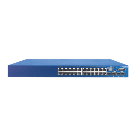
Stac k L ink Master Powe r Select Diag Module Console 10/100/1000 Mbps RJ-45 Por ts System Status LEDs SFP Slots Figure 1-1 PowerLION-24TP Front Panel If an SFP transceiver is plugged in, the corresponding RJ-45 port is disabled for ports 21-24. -
Page 22: Switch Architecture
R edundant P ower S ocket Module S lot S tacking P orts Figure 1-2 PowerLION-24TP Rear Panel Switch Architecture The Gigabit Ethernet Switches employ a wire-speed, non-blocking switching fabric. This permits simultaneous wire-speed transport of multiple packets at low latency on all ports. -
Page 23: Description Of Hardware
Description of Hardware Description of Hardware 10/100/1000BASE-T Ports The switches contain RJ-45 ports that operate at 10 Mbps or 100 Mbps, half or full duplex, or at 1000 Mbps, full duplex. Because all ports on these switches support automatic MDI/MDI-X operation, you can use straight-through cables for all network connections to PCs or servers, or to other switches or hubs. -
Page 24: Port And System Status Leds
Introduction Port and System Status LEDs These switches include a display panel for key system and port indications that simplify installation and network troubleshooting. The LEDs, which are located on the front panel for easy viewing, are shown below and described in the following tables. -
Page 25: Table 1-2 System Status Leds
Description of Hardware System St atus LED s St ac k Maste r St ack ID St ack Link Master Powe r Select Diag Module Consol e Figure 1-4 System LEDs Table 1-2 System Status LEDs Condition Status Power Green Internal Power is operating normally. -
Page 26: Optional Redundant Power Unit
Introduction Optional Redundant Power Unit The switch supports an optional Redundant Power Unit (RPU), that can supply power to the switch in the event of failure of the internal power supply. Power Supply Sockets There are two power sockets on the rear panel of each switch. The standard power socket is for the AC power cord. -
Page 27: Extender Module Leds
Features and Benefits Extender Module LEDs The optional slide-in module supports its own integrated LED indicators on the module panel. The following table describes the LEDs. Table 1-3 Module LEDs Condition Status On/Flashing Green Port has a valid link at 10 Gbps. Flashing indicates activity. Link/Activity There is no traffic passing through the port. -
Page 28: Performance
Introduction Performance • Transparent bridging. • Aggregate duplex bandwidth of up to 48 Gbps. • Switching table with a total of 16K MAC address entries and 8K IP address entries • Provides store-and-forward switching for intra-VLAN traffic, and IP routing for inter-VLAN traffic. -
Page 29: Chapter 2: Network Planning
Chapter 2: Network Planning Introduction to Switching A network switch allows simultaneous transmission of multiple packets via non-crossbar switching. This means that it can partition a network more efficiently than bridges or routers. These switches have, therefore, been recognized as one of the most important building blocks for today’s networking technology. -
Page 30: Application Examples
Network Planning Application Examples The Gigabit Ethernet Switches are not only designed to segment your network, but also to provide a wide range of options in setting up network connections and linking VLANs or IP subnets. Some typical applications are described below. Collapsed Backbone The Gigabit Ethernet Switches are an excellent choice for mixed Ethernet, Fast Ethernet, and Gigabit Ethernet installations where significant growth is expected in... -
Page 31: Network Aggregation Plan
Application Examples Network Aggregation Plan With 24 bridging ports (i.e., 24 distinct collision domains), a Gigabit switch stack can collapse a complex network down into a single efficient bridged node, increasing overall bandwidth and throughput. In the figure below, the 10/100/1000BASE-T ports in a stack of 24-port Gigabit Ethernet switches are providing 1000 Mbps connectivity through stackable switches. -
Page 32: Remote Connections With Fiber Cable
Network Planning Remote Connections with Fiber Cable Fiber optic technology allows for longer cabling than any other media type. A 1000BASE-SX (MMF) link can connect to a site up to 550 meters away, a 1000BASE-LX (SMF) link up to 5 km, and a 1000BASE-LH link up to 70 km. This allows a Gigabit Ethernet Switch stack to serve as a collapsed backbone, providing direct connectivity for a widespread LAN. -
Page 33: Making Vlan Connections
Application Examples Making VLAN Connections These switches support VLANs which can be used to organize any group of network nodes into separate broadcast domains. VLANs confine broadcast traffic to the originating group, and can eliminate broadcast storms in large networks. This provides a more secure and cleaner network environment. -
Page 34: Using Layer 3 Routing
Network Planning Using Layer 3 Routing VLANs can significantly enhance network performance and security. However, if you use conventional routers to interconnect VLANs, you can lose most of your performance advantage. These Gigabit Ethernet Switches are routing switches that provide wire-speed routing, which allows you to eliminate your conventional IP routers, except for a router to handle non-IP protocols and a gateway router linked to the WAN. -
Page 35: Application Notes
Application Notes Application Notes Full-duplex operation only applies to point-to-point access (such as when a switch is attached to a workstation, server or another switch). When the switch is connected to a hub, both devices must operate in half-duplex mode. For network applications that require routing between dissimilar network types, you can attach this switch directly to a multi-protocol router. - Page 36 Network Planning...
-
Page 37: Chapter 3: Installing The Switch
Chapter 3: Installing the Switch Selecting a Site Switches can be mounted in a standard 19-inch equipment rack or on a flat surface. Be sure to follow the guidelines below when choosing a location. • The site should: - be at the center of all the devices you want to link and near a power outlet. - be able to maintain its temperature within 0 to 45 °C (32 to 113 °F) and its humidity within 5% to 95%, non-condensing. -
Page 38: Equipment Checklist
Installing the Switch RJ-45 Connec tor Figure 3-1 RJ-45 Connections Equipment Checklist After unpacking the switch, check the contents to be sure you have received all the components. Then, before beginning the installation, be sure you have all other necessary installation equipment. Package Contents •... -
Page 39: Mounting
Mounting Mounting A switch unit can be mounted in a standard 19-inch equipment rack or on a desktop or shelf. Mounting instructions for each type of site follow. Rack Mounting Before rack mounting the switch, pay particular attention to the following factors: •... -
Page 40: Desktop Or Shelf Mounting
Installing the Switch Mount the device in the rack, using four rack-mounting screws (not provided). M a s S t a c te r k ID S e le St ac St ac k k M as Li nk te r P o w R P U M o d... -
Page 41: Installing An Optional Module Into The Switch
Installing an Optional Module into the Switch If installing a single switch only, go to “Connecting to a Power Source” at the end of this chapter. If installing multiple switches, attach four adhesive feet to each one. Place each device squarely on top of the one below, in any order. if also installing RPUs, place them close to the stack. -
Page 42: Installing An Optional Sfp Transceiver
Installing the Switch Installing an Optional SFP Transceiver M a s S t a c t e r k ID S e le S t a c S t a c k k M a L in k s te r P o w R P U M o d... -
Page 43: Figure 3-7 Making Stacking Connections
Connecting Switches in a Stack To connect up to eight switches in a stack, perform the following steps: Plug one end of the stack cable (ordered separately) in the Down (right) port of the top unit. Plug the other end of the stack cable into the Up (left) port of the next unit. Repeat steps 1 and 2 for each unit in the stack. -
Page 44: Stacking Topologies
Installing the Switch Stacking Topologies All units in the stack must be connected via stacking cable. You can connect units in a simple cascade configuration, connecting Up ports to Down ports, from the top unit to the bottom unit. Using this “line” topology, if any link or unit in the stack fails, the stack splits and two separate segments are formed. -
Page 45: Connecting To The Console Port
Connecting to the Console Port Connecting to the Console Port The DB-9 serial port on the switch’s front panel is used to connect to the switch for out-of-band console configuration. The on-board configuration program can be accessed from a terminal or a PC running a terminal emulation program. The pin assignments used to connect to the serial port are provided in the following table. - Page 46 Installing the Switch 3-10...
-
Page 47: Chapter 4: Making Network Connections
Chapter 4: Making Network Connections Connecting Network Devices This switch is designed to interconnect multiple segments (or collision domains). It can be connected to network cards in PCs and servers, as well as to hubs, switches or routers. It may also be connected to devices using optional Xenpak, or SFP transceivers. -
Page 48: Connecting To Pcs, Servers, Hubs And Switches
Making Network Connections Connecting to PCs, Servers, Hubs and Switches Attach one end of a twisted-pair cable segment to the device’s RJ-45 connector. Figure 4-1 Making Twisted-Pair Connections If the device is a PC card and the switch is in the wiring closet, attach the other end of the cable segment to a modular wall outlet that is connected to the wiring closet. -
Page 49: Fiber Optic Sfp Devices
Fiber Optic SFP Devices Equipment Rack (side view) Network Switch St ac k ID Stack Link Stac k Maste r Master Powe r CheetahSwitchWorkgroup-4549 Select RP U Diag w it it c h 1 0 /1 6 7 2 4 L 3 /1 0 0 Module Console... -
Page 50: 10 Gbps Fiber Optic Connections
Making Network Connections Check that the fiber terminators are clean. You can clean the cable plugs by wiping them gently with a clean tissue or cotton ball moistened with a little ethanol. Dirty fiber terminators on fiber cables will impair the quality of the light transmitted through the cable and lead to degraded performance on the port. -
Page 51: Connectivity Rules
Connectivity Rules Remove and keep the port’s protective cover. When not connected to a fiber cable, the cover should be replaced to protect the optics. Check that the fiber terminators are clean. You can clean the cable plugs by wiping them gently with a clean tissue or cotton ball moistened with a little ethanol. -
Page 52: 10 Gbps Ethernet Collision Domain
Making Network Connections Category 5e specification includes test parameters that are only recommendations for Category 5. Therefore, the first step in preparing existing Category 5 cabling for running 1000BASE-T is a simple test of the cable installation to be sure that it complies with the IEEE 802.3-2002 standards. -
Page 53: 1000 Mbps Gigabit Ethernet Collision Domain
Connectivity Rules 1000 Mbps Gigabit Ethernet Collision Domain Table 4-4 Maximum 1000BASE-T Gigabit Ethernet Cable Length Cable Type Maximum Cable Length Connector Category 5, 5e, 6 100-ohm UTP or STP 100 m (328 ft) RJ-45 Table 4-5 Maximum 1000BASE-SX Gigabit Ethernet Cable Length Fiber Size Fiber Bandwidth Maximum Cable Length... -
Page 54: Cable Labeling And Connection Records
Making Network Connections Cable Labeling and Connection Records When planning a network installation, it is essential to label the opposing ends of cables and to record where each cable is connected. Doing so will enable you to easily locate inter-connected devices, isolate faults and change your topology without need for unnecessary time consumption. -
Page 55: Appendix A: Troubleshooting
Appendix A: Troubleshooting Diagnosing Switch Indicators Table A-1 Troubleshooting Chart Symptom Action Power LED is Off • Check connections between the switch, the power cord, and the wall outlet. • Contact your dealer for assistance. Power LED is Amber • Internal power supply has failed. Contact your local dealer for assistance. -
Page 56: Power And Cooling Problems
Troubleshooting Power and Cooling Problems If the power indicator does not turn on when the power cord is plugged in, you may have a problem with the power outlet, power cord, or internal power supply. However, if the unit powers off after running for a while, check for loose power connections, power losses or surges at the power outlet, and verify that the fans on the unit are unobstructed and running prior to shutdown. -
Page 57: Stack Troubleshooting
Stack Troubleshooting Stack Troubleshooting If a stack fails to initialize or function, first check the following items: • Check that all stacking cables are properly connected. • Check if any stacking cables appear damaged. • Check that only one Stack Master button is pressed in. •... - Page 58 Troubleshooting...
-
Page 59: Appendix B: Cables
Appendix B: Cables Twisted-Pair Cable and Pin Assignments For 10/100BASE-TX connections, the twisted-pair cable must have two pairs of wires. For 1000BASE-T connections the twisted-pair cable must have four pairs of wires. Each wire pair is identified by two different colors. For example, one wire might be green and the other, green with white stripes. -
Page 60: Straight-Through Wiring
Cables Table B-1 10/100BASE-TX MDI and MDI-X Port Pinouts MDI Signal Name MDI-X Signal Name Transmit Data plus (TD+) Receive Data plus (RD+) Transmit Data minus (TD-) Receive Data minus (RD-) Receive Data plus (RD+) Transmit Data plus (TD+) Receive Data minus (RD-) Transmit Data minus (TD-) 4,5,7,8 Not used... -
Page 61: 1000Base-T Pin Assignments
Twisted-Pair Cable and Pin Assignments You must connect all four wire pairs as shown in the following diagram to support Gigabit Ethernet connections. E IA/T IA 568B R J -45 Wiring S tandard 10/100B AS E -T X Cros s over Cable White/Orange S tripe Orange White/G reen S tripe... -
Page 62: Cable Testing For Existing Category 5 Cable
Cables Cable Testing for Existing Category 5 Cable Installed Category 5 cabling must pass tests for Attenuation, Near-End Crosstalk (NEXT), and Far-End Crosstalk (FEXT). This cable testing information is specified in the ANSI/TIA/EIA-TSB-67 standard. Additionally, cables must also pass test parameters for Return Loss and Equal-Level Far-End Crosstalk (ELFEXT). -
Page 63: Appendix C: Specifications
Appendix C: Specifications Physical Characteristics Ports 20 10/100/1000BASE-T, with auto-negotiation 4 10/100/1000BASE-T ports shared with four SFP transceiver slots 1 10GBASE extender module slot for Xenpak transceivers Two slots for stacking connections Network Interface Ports 1-24: RJ-45 connector, auto MDI/X 10BASE-T: RJ-45 (100-ohm, UTP cable;... -
Page 64: Switch Features
Specifications Humidity Operating: 5% to 95% (non-condensing) AC Input 100 to 240 V, 50-60 Hz, 2A Power Supply Internal, auto-ranging transformer: 100 to 240 VAC, 47 to 63 Hz External, supports connection for redundant power supply Power Consumption 66 Watts (without expansion module) 80 Watts (with expansion module) Maximum Current 1 A @ 110 VAC (without expansion module) -
Page 65: Standards
Standards Standards IEEE 802.3-2002 Ethernet, Fast Ethernet, Gigabit Ethernet IEEE 802.3ae 10 Gigabit Ethernet IEEE 802.1D Spanning Tree Protocol IEEE 802.1w Rapid Spanning Tree Protocol IEEE 802.1s Multiple Spanning Tree Protocol ISO/IEC 8802-3 Compliances CE Mark Emissions FCC Class A Industry Canada Class A EN55022 (CISPR 22) Class A EN 61000-3-2/3... - Page 66 Specifications Standards IEEE 802.3ae 10 Gigabit Ethernet...
-
Page 67: Installationsort Auswählen
Appendix D: German Instructions Installationsort Auswählen (Selecting a Site - German) Der Switch kann in ein Standard-19-Zoll-Schaltschrank oder auf eine flache Ebene montiert werden. Zum Auswählen eines Standortes beachten Sie bitte die nachstehenden Richtlinien. • Der Installationsort sollte: - sich in der Mitte aller anzuschließenden Geräte sowie in der Nähe einer Netzsteckdose befinden;... -
Page 68: Montage (Rack Mounting Instructions - German
German Instructions Montage (Rack Mounting Instructions - German) Die Geräte können in einen Standard-19-Zoll-Schaltschrank montiert oder auf einem Arbeitstisch aufgestellt werden Schaltschrank-Montage Beachten Sie die folgenden Faktoren, bevor Sie die Schaltschrank-Montage beginnen: • Temperatur: Da die Temperatur innerhalb eines Schaltschrankes höher als die Raumumgebungstemperatur sein kann, stellen Sie bitte sicher, dass die Schaltschrankumgebungstemperatur innerhalb des angegebenen Betriebstemperaturbereichs liegt. - Page 69 Glossary 10BASE-T IEEE 802.3 specification for 10 Mbps Ethernet over two pairs of Category 3, 4, or 5 UTP cable. 100BASE-TX IEEE 802.3u specification for 100 Mbps Fast Ethernet over two pairs of Category 5 or better UTP cable. 1000BASE-LH Long-haul Gigabit Ethernet over two strands of 9/125 micron core fiber cable.
- Page 70 Glossary Collision A condition in which packets transmitted over the cable interfere with each other. Their interference makes both signals unintelligible. Collision Domain Single CSMA/CD LAN segment. CSMA/CD CSMA/CD (Carrier Sense Multiple Access/Collision Detect) is the communication method employed by Ethernet, Fast Ethernet, or Gigabit Ethernet. End Station A workstation, server, or other device that does not forward traffic.
- Page 71 Glossary IEEE 802.3ae Defines the physical layer specifications for 10 Gigabit Ethernet. IEEE 802.3u Defines CSMA/CD access method and physical layer specifications for 100BASE-TX Fast Ethernet. (Now incorporated in IEEE 802.3-2002.) IEEE 802.3z Defines CSMA/CD access method and physical layer specifications for 1000BASE Gigabit Ethernet.
- Page 72 Glossary RJ-45 Connector A connector for twisted-pair wiring. Switched Ports Ports that are on separate collision domains or LAN segments. Telecommunications Industry Association Transmission Control Protocol/Internet Protocol (TCP/IP) Protocol suite that includes TCP as the primary transport protocol, and IP as the network layer protocol.
- Page 73 Index Numerics VLAN connections 10 Gbps connectivity rules 10 Mbps connectivity rules brackets, attaching 100 Mbps connectivity rules buffer size 1000 Mbps connectivity rules cable Ethernet cable compatibili- 1000BASE-LH fiber cable lengths labeling and connection re- 1000BASE-LX fiber cable cords lengths lengths 1000BASE-SX...
- Page 74 Index equipment checklist Ethernet connectivity rules laser safety LC port connections LED indicators Fast Ethernet connectivity ru- Diag Module features Power management problems switch fiber cables Stack ID full-duplex connectivity Stack Link Stack Master grounding for racks location requirements IEEE 802.3 Ethernet management IEEE 802.3ae 10 Gigabit agent...
- Page 75 Index physical out-of-band management power standards package contents IEEE pin assignments status LEDs 1000BASE-T surge suppressor, using 10BASE-T/100BASE-TX switch architecture switching, introduction to console port DB-9 temperature within a rack ports, connecting to troubleshooting power, connecting to in-band access problems, troubleshooting power and cooling pro- blems rack mounting...
- Page 76 Index Index-4...
Need help?
Do you have a question about the PowerLION-24TP and is the answer not in the manual?
Questions and answers