Sign In
Upload
Download
Table of Contents
Contents
Add to my manuals
Delete from my manuals
Share
URL of this page:
HTML Link:
Bookmark this page
Add
Manual will be automatically added to "My Manuals"
Print this page
×
Bookmark added
×
Added to my manuals
Manuals
Brands
Hirschmann Manuals
Switch
MSP30
User manual
Hirschmann MSP30 User Manual
Mice switch power/mice switch media modules
Hide thumbs
Also See for MSP30
:
User manual
(58 pages)
1
2
Table Of Contents
3
4
5
6
7
8
9
10
11
12
13
14
15
16
17
18
19
20
21
22
23
24
25
26
27
28
29
30
31
32
33
34
35
36
37
38
39
40
41
42
43
44
45
46
47
48
49
50
51
52
53
54
55
56
57
58
59
60
61
62
63
64
65
66
67
68
69
70
71
72
73
74
75
76
77
78
79
80
81
82
83
84
85
86
87
88
89
90
91
92
93
94
page
of
94
Go
/
94
Contents
Table of Contents
Bookmarks
Table of Contents
Table of Contents
Safety Instructions
About this Manual
Key
1 Description
General Device Description
Basic Device
Media Modules
Device Name and Product Code
Device Views
Basic Device
Media Modules
Number of Ports and Connections
Power Supply
Supply Voltage with the Characteristic Value C
Supply Voltage with the Characteristic Value P
SFP Transceiver
Ethernet Ports
Display Elements
Device State
Digital Input
MSM20 Media Modules
MSM40 Media Modules
MSM22, MSM42 and MSM46 Media Modules
MSM50 Media Modules
MSM24 I/O Module
Management Interfaces 1.9.1 V.24 Interface (External Management)
SD Card Interface (Optional)
USB Interface
Input/Output Interfaces
Signal Contact
Digital Input
Checking the Package Contents
Installing the SD Card (Optional)
Installing and Grounding the Device
Installing the Device Onto the DIN Rail
Mounting on a Flat Surface
Grounding the Device
Connecting the Terminal Blocks
Supply Voltage with the Characteristic Value C
Supply Voltage with the Characteristic Value P
Signal Contact
Connecting the Ferrite
Installing Terminal Blocks, Switching on the Supply Voltage
Installing Media Modules
Device Variants Featuring Customer-Specific Version with the Characteristic Value HH
Device Variants Featuring Customer-Specific Version with the Characteristic Value HX
Connecting the External Poe Supply Voltage of Media Module MSM46
Connecting an I/O Module
Connecting Actuators and Sensors
Installing an SFP Transceiver (Optional)
Connecting Data Cables
10/100/1000 Mbit/S Twisted Pair Port
1/2.5 Gbit/S F/O Port
100/1000 Mbit/S F/O Port
3 Basic Settings
4 Monitoring the Ambient Air Temperature
5 Upgrading Software
6 Maintenance and Service
7 Disassembly
Removing an SFP Transceiver (Optional)
Removing a Media Module
Device Variants Featuring Customer-Specific Version with the Characteristic Value HH
Device Variants Featuring Customer-Specific Version
With the Characteristic Value HX
Advertisement
Quick Links
1
General Device Description
2
Basic Device
3
Power Supply
4
Msm40 Media Modules
5
Management Interfaces 1.9.1 V.24 Interface (External Management)
6
Basic Settings
Download this manual
User Manual
Installation
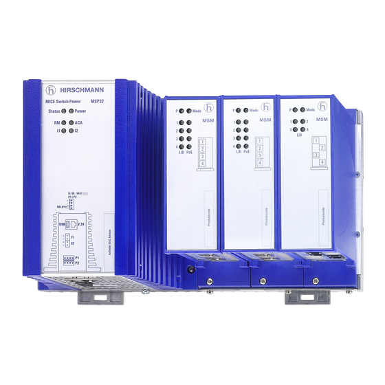
MICE Switch Power - MSP30/32/40/42
MICE Switch Media modules - MSM20/22/24/40/42/46/50
Installation MSP30/32/40/42 and MSM20/22/24/40/42/46/50
Technical support
Release 12 06/2018
https://hirschmann-support.belden.com
Table of
Contents
Previous
Page
Next
Page
1
2
3
4
5
Advertisement
Table of Contents
Need help?
Do you have a question about the MSP30 and is the answer not in the manual?
Ask a question
Questions and answers
Related Manuals for Hirschmann MSP30
Switch Hirschmann MSP30 User Manual
Mice switch power (58 pages)
Switch Hirschmann MSM20 User Manual
Mice switch media modules (60 pages)
Switch Hirschmann MSM20 User Manual
Installation mice switch media modules (56 pages)
Switch Hirschmann RS20 User Manual
Redundancy configuration industrial ethernet (gigabit) switch (100 pages)
Switch Hirschmann RS20 Reference Manual
Ethernet gigabit switch (572 pages)
Switch Hirschmann RS20 User Manual
(294 pages)
Switch Hirschmann MACH 100 User Manual
Industrial ethernet (gigabit-)switch (76 pages)
Switch Hirschmann RS20 User Manual
Industrial (284 pages)
Switch Hirschmann RS20 Reference Manual
Industrial ethernet (gigabit) switch (204 pages)
Switch Hirschmann RS20 User Manual
Redundancy configuration industrial ethernet (gigabit-)switch (128 pages)
Switch Hirschmann RS20 Reference Manual
Web-based interface industrial ethernet (gigabit) switch (172 pages)
Switch Hirschmann PowerMICE MS4128 User Manual
Powermice series industrial ethernet switch (58 pages)
Switch Hirschmann MSP40 User Manual
Mice switch power/mice switch media modules (94 pages)
Switch Hirschmann MACH104-20TX-F User Manual
Industrial ethernet workgroup switch full gigabit family (38 pages)
Switch Hirschmann MACH4000 Series User Manual
Modular industrial ethernet backbone switch (68 pages)
Switch Hirschmann MACH1040 User Manual
Industrial ethernet ruggedized switch (62 pages)
This manual is also suitable for:
Msp40
Msp32
Msp42
Msm22
Msm20
Msm24
...
Show all
Msm40
Msm42
Msm50
Msm46
Table of Contents
Save PDF
Print
Rename the bookmark
Delete bookmark?
Delete from my manuals?
Login
Sign In
OR
Sign in with Facebook
Sign in with Google
Upload manual
Upload from disk
Upload from URL


Need help?
Do you have a question about the MSP30 and is the answer not in the manual?
Questions and answers