Table of Contents
Advertisement
Quick Links
Made in China | INS-30011-A-SARATOGA-SP 10-9-18
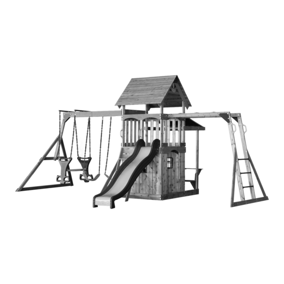
Saratoga
Model # 30011
assembly time may vary based on skill level
For the most up to date assembly manual,
to register your set, or to order replacement parts please visit
www.backyarddisovery.com
SAVE THIS ASSEMBLY MANUAL FOR FUTURE REFERENCE IN THE
EVENT THAT YOU NEED TO ORDER REPLACEMENT PARTS.
Para obtener instrucciones en español, visite www.backyarddiscovery.com
Wooden Swing Set
Owner's Manual & Assembly Instructions
average 2 person assembly time
10
MANUFACTURED BY:
Backyard Discovery
3305 Airport Drive
Pittsburg, KS 66762
800-856-4445
Before you begin
FOR QUICK &
EASY ASSEMBLY
FIND 3D INSTRUCTIONS
FOR THIS PRODUCT IN
DOWNLOAD THE FREE APP
Advertisement
Table of Contents

Related Manuals for Backyard Discovery Saratoga 30011


Summary of Contents for Backyard Discovery Saratoga 30011
- Page 1 MANUFACTURED BY: Saratoga Wooden Swing Set Backyard Discovery 3305 Airport Drive Pittsburg, KS 66762 Owner’s Manual & Assembly Instructions Model # 30011 800-856-4445 Before you begin average 2 person assembly time FOR QUICK & EASY ASSEMBLY FIND 3D INSTRUCTIONS FOR THIS PRODUCT IN...
- Page 2 INSTALLATION SERVICES AVAILABLE! Need a helping hand? Let our team of professionals handle the installation for you! *Installation services are only available to U.S. customers. With Go Con gure, we bring you 18 years of experience right to your doorstep. We service a wide array of indoor and outdoor recreation products that most consumers don’t have the time or ability to deliver &...
- Page 3 Owner’s Manual Please Read This Before Starting Assembly MISSING A PART? CALL US BEFORE GOING BACK TO THE STORE e store where you made your purchase does not stock parts for this item. If you have assembly questions or you are missing or have damaged parts, please call 1-800-856-4445 or visit www.backyarddiscovery.com...
-
Page 4: Limited Warranty
All wood carries a ve (5) year pro-rated warranty against rot and decay. Refer to the schedule below for charges associated with replacement of parts under this Limited Warranty. In addition, Backyard Discovery will replace any parts within the rst 30 days from date of purchase found to be missing from or damaged in the original packaging. -
Page 5: Burn Hazard
Owner’s Manual Operating Instructions and Safety Warnings WARNING: BURN HAZARD • Pay special attention to plastic and metal surfaces as they may be hot enough to cause burns. • Always check the temperature of the product before NOTE: letting your children play on it. •... - Page 6 Owner’s Manual Please Read This Before Starting Assembly Positioning Your Playcenter Suggested Playground Surfacing • e playcenter is designed to be installed on a level • Do not install home playground equipment over surface by an adult with an adult helper. Place concrete, asphalt, packed earth, grass, carpet, or any in a at area of your yard to minimize ground other hard surface.
- Page 7 Owner’s Manual Please Read This Before Starting Assembly APPENDIX A The following information is from the United States X3.1.3.2 Do not install loose- ll surfacing over hard surfaces such as concrete or asphalt. Consumer Product Safety Commission’s Information X3.1.4 Poured-In-Place Surfaces or Pre-Manufactured Sheet for playground surfacing material;...
-
Page 8: Instructions For Proper Maintenance
Check all moving parts including swing seats, third party person or service to assemble this product. ropes, cables, and chains for wear, rust, or other Backyard Discovery assumes no responsibility or deterioration. Replace as needed. liability for any charge incurred by the Customer for any assembly services’... - Page 9 About Our Wood Backyard Discovery uses 100% Cedar (C. Lanceolata) wood. Although we take great care in selecting the best quality lumber available, wood is still a product of nature and susceptible to weathering which can change the appearance of your set.
-
Page 10: Assembly Tips
Owner’s Manual Assembly Tips Protrusion Hazard Incorrect Correct If you see exposed threads and your bolt protrudes beyond the T-Nut you may have over tightened the bolt. To eliminate this, remove the bolt and add washers to eliminate the problem. Proper Hardware Assembly Bolt and T-Nut Assembly Tap T-nut into the provided hole. - Page 11 Owner’s Manual Assembly Tips ASSEMBLY TIP: Keep an eye out for these boxes which will contain helpful pictures and information making the assembly process as quick and painless as possible. Sorting Wood When removing the wood from the boxes we recommend arranging them by part number before you begin assembly.
-
Page 12: Tools Required For Installation
Owner’s Manual Tools Required for Installation (These are the tools that are generally required for assembly of our swing sets. These tools are not included in the swing set purchase.) (Square) (Open End Wrenches 1/2") (Level 24") (3/8" Drive Ratchet, 1/2" STD (Tape Measure) (Claw Hammer) Sockets 1/2"... - Page 13 Basic Setup Dimensions Place the set on level ground, not less than 6 ft [2 m] from any structure or obstruction such as a fence, garage, house, overhanging branches, laundry lines, or electrical wires. Safe Play Zone 223" [5.8 m] 50"...
-
Page 14: Parts Identification
Parts Identification Wood Components (NOT TO SCALE) K91 - ROOF SLAT - W100917 3/8"x3 3/8"x50" (11x86x1270) H74 - LEFT UPRIGHT - W100608 1"x3 3/8"x50 3/4" (24x86x1290) H75 - RIGHT UPRIGHT - W100609 1"x3 3/8"x50 3/4" (24x86x1290) SB74 - SWING BEAM - W102304 N6 - ANGLED SUNBURST - W100916 2"x5 1/4"x89 1/2"... - Page 15 Parts Identification Wood Components (NOT TO SCALE) W71 - SWING BEAM SUPPORT - W102305 2"x3 3/8"x46 1/8" (50x86x1170) E78 - MONKEY BAR UPRIGHT - W102370 1 3/8"x3 3/8"x74 3/4" (36x86x1900) E77 - ANGLE BRACE - W100991 1 3/8"x3 3/8"x74 3/8" (36x86x1890) H82 - MONKEY BAR GROUND BOARD - W100994 1"x3 3/8"x70 3/8"...
- Page 16 Parts Identification Wood Components (NOT TO SCALE) G3 - CABIN ARCH - W101096 1"x5 1/4"x41 1/8" (24x134x1044) M2 - WALL RAIL - W101097 5/8"x3 3/8"x67 5/8" (16x86x1718) M7 - WALL RAIL - W101099 5/8"x3 3/8"x43" (16x86x1092) N2 - TIE SLAT - W101103 L2 - OUTER WALL SLAT - W101100 5/8"x2 3/8"x14 5/8"...
- Page 17 Parts Identification Wood Components (NOT TO SCALE) N1 - CENTER RAIL - W101113 5/8"x2 3/8"x25 5/8" (16x60x652) M14 - WALL SLAT - W101115 5/8"x3 3/8"x25 5/8" (16x86x652) M11 - WALL RAIL - W101116 5/8"x3 3/8"x41 1/8" (16x86x1044) M10 - PICNIC TABLE BOARD - W101118 5/8"x3 3/8"x41 5/8"...
- Page 18 Parts Identification Hardware - SCREW PPH 4x5/8 BLK (11) - BOLT WH 5/16x1/2 - H100115 (11) -H100127 - BOLT PTH 1/4x1 - H100061 - SCREW PWH 8x5/8 (11) - BOLT WH 5/16x1 - H100008 -H100128 - BOLT HEX 5/16x1 1/4 - H100042 (46) - BOLT WH 5/16x1 1/2 - H100010 (81)
- Page 19 Parts Identification Hardware (258) BR - SCREW PFH 8x1 1/8 - H100088 CE - WASHER FLAT 9x18 - H100106 (52) BQ - SCREW PFH 8x1 1/4 - H100087 (86) BP - SCREW PFH 8x1 1/2 - H100086 CD - WASHER FLAT 8x27 (24) -H100105 BS - SCREW PFH 8x1 3/4 - H100089...
- Page 20 Parts Identification Accessories (NOT TO SCALE) EK - SLIDE RAIL 8' GREEN RIGHT - A100054 QZ - TRIANGLE PLATE 100° 5 HOLE -A100294 EL - SLIDE RAIL 8' GREEN LEFT - A100055 DE - TRIANGLE PLATE 90 5 HOLE BYD GREEN -A100011 EM - SLIDE BED 8' YELLOW - A100056...
- Page 21 Parts Identification Accessories (NOT TO SCALE) GK - WINDOW 216x267 GREEN -A100146 JZ - PICNIC TARP - A100143 EB - WINDOW FRAME GREEN EY - TUBING CAP GLIDER SUPPORT 343x444.5 -A100067 -A100044 DL - GLIDER SEAT YELLOW - A100023 EX - GLIDER BUSHING BYD GREEN - A100066 DK - GLIDER ARM BYD GREEN - A100022 EW - GLIDER SUPPORT BYD GREEN - A100065 SQ - "A"...
- Page 22 8 FOOT SLIDE ASSEMBLY PHASE 1 Phase Notes DRILL 3 HOLES AT ONE END OF THE PLASTIC SLIDE BED USING A 5/16" DRILL BIT AND USING THE DIMENSIONS SHOWN BELOW. THIS END WILL BE THE TOP OF THE SLIDE. TAKE NOTE OF SLIDE BED SURFACE FINISH, THE DULL SIDE WILL BE TOWARDS THE GROUND. PLACE SLIDE BRACE CENTERED ON THE BOTTOM (DULL SIDE) AND 1/4"...
- Page 23 8 FOOT SLIDE ASSEMBLY PHASE 2 Phase Notes PLACE 1 SLIDE RAIL ON A FLAT SURFACE AND BEGIN INSERTING SLIDE BED AT THE BOTTOM OF THE SLIDE RAIL. PUT SLIDE SUPPORT BOTTOM INTO THE SUPPORT POCKET AT THE BOTTOM OF THE RAIL AND HAVE A HELPER BEND THE SLIDE BED TOWARDS THE TOP OF THE SLIDE AND INSERT THE BED INTO THE SLIDE CAVITY.
- Page 24 4 Ft Ladder Phase 1 & 2 Phase Notes DESCRIPTION LABEL • Assemble with hardware as shown. LEFT UPRIGHT • Center rungs in rail grooves. LADDER RUNG SCREW PFH 8x2 SCREW PFH 8x2 DESCRIPTION LABEL RIGHT UPRIGHT SCREW PFH 8x2 SCREW PFH 8x2...
- Page 25 4 Ft Ladder Phase 3 Phase Notes • Assemble with hardware as shown. SCREW PFH 8x2 DESCRIPTION LABEL REAR SUPPORT SCREW PFH 8x2...
-
Page 26: Swing Beam Assembly
SB74 - SWING BEAM - W102304 2"x5 1/4"x89 1/2" (50x134x2274) GD - L BRACKET 66x66x127 - A100140 QZ - TRIANGLE PLATE 100° 5 HOLE - A100294 SWING BEAM ASSEMBLY STEP 1 BOLT WH 5/16x1 3/4 ATTACH (2) QZ TRIANGLE PLATES TO SB74 SWING BEAM USING BOLT HEX 1-3/4"... - Page 27 H79 - END SUPPORT - W100992 W71 - SWING BEAM SUPPORT - W102305 1"x3 1/2"x42" (24x86x1072) 2"x3 3/8"x46 1/8" (50x86x1170) E77 - ANGLE BRACE - W100991 H80 - GROUND BOARD - W100990 1 3/8"x3 3/8"x74 3/8" (36x86x1890) 1"x3 3/8"x87 3/8" (24x86x2218) SWING BEAM ASSEMBLY BOLT WH STEP 2...
- Page 28 SWING BEAM ASSEMBLY STEP 3 ATTACH (2) QZ TRIANGLE PLATES TO W71 SWING BEAM SUPPORT USING (2) 1-3/4" BOLTS, LOCK WASHERS AND 7/8" BARREL NUTS (FIG.1). EW - GLIDER SUPPORT BYD GREEN - A100065 INSERT (4) SWING HANGER QUICK LINKS INTO (4) EX BUSHINGS AND THEN ATTACH SWING HANGER QUICK LINKS TO EW GLIDER SUPPORTS USING (4) FLAT WASHERS AND EX - GLIDER BUSHING BYD GREEN - A100066...
- Page 29 YELLOW & GREEN GLIDER 38.5" Notes Assemble with accessories as shown. QTY. DESCRIPTION LABEL 5/16 LOCK NUT 8x27 FLAT WASHER BOLT WH 5/16x5-3/4 QUICKLINK GREEN ARM GLIDER YELLOW SEAT 38.5" GREEN CHAIN CHAIN GREEN 38.5" QUICK LINK BOLT WH 5/16x5-3/4 WASHER FLAT 8x27 NUT LOCK 5/16 GLIDER SEAT YELLOW...
-
Page 30: Monkey Bar Assembly
E71 - MONKEY BAR RAIL - W102369 EJ - L BRACKET 54x67 - A100053 1 3/8"x3 3/8"x60 5/8" (36x86x1539) QZ - TRIANGLE PLATE 100 5 HOLE - A100294 MONKEY BAR ASSEMBLY STEP 1 BOLT WH 5/16x1-1/2 BOLT WH 5/16x2 YOU WILL BUILD A LEFT AND RIGHT TOP RAIL IN THIS STEP. AFTER BUILDING LEFT ASSEMBLY AS SHOWN, REPEAT STEPS FOR A RIGHT ASSEMBLY. - Page 31 E78 - MONKEY BAR UPRIGHT - W102370 1 3/8"x3 3/8"x74 3/4" (36x86x1900) MONKEY BAR ASSEMBLY STEP 2 ASSEMBLE WITH HARDWARE AS SHOWN. REPEAT PROCESS FOR OTHER SIDE OF MONKEY BAR ASSEMBLY. BOLT WH 5/16x1-1/2 T-NUT 5/16...
- Page 32 EC - METAL RUNG 559 - A100045 MONKEY BAR ASSEMBLY STEP 3 ASSEMBLE AS SHOWN INTO PRE-DRILLED HOLES. SCREW TAPPING 14x1-1/2...
- Page 33 H81 - MONKEY BAR BRACE - W100993 1"x3 3/8"x53 1/4" (24x86x1352) H82 - MONKEY BAR GROUND BOARD - W100994 1"x3 3/8"x70 3/8" (24x86x1786) MONKEY BAR ASSEMBLY BOLT WH 5/16x1-1/2 LAG SCREW BOLT HEX WH 5/16x2 5/16x2-3/4 WASHER LOCK EXT WASHER 8x19 LOCK INT 8x15...
- Page 34 EA - HAND GRIP YELLOW PLASTIC - A100043 MONKEY BAR ASSEMBLY LAG SCREW WH 1/4x1-1/2 WASHER LOCK EXT 6x15 STEP 5 ASSEMBLE WITH HARDWARE AS SHOWN.
- Page 35 • (26) D - NUT BARREL WH 5/16x7/8 - H100005 • (1) E1 - FORT UPRIGHT - W101084 • (26) AD - WASHER LOCK EXT 12x19 - H100031 • (1 E2 - FORT UPRIGHT - W101104 • (30) AC - WASHER LOCK EXT 8x19 - H100030 •...
-
Page 36: Fort Assembly
Fort Assembly Phase 2 Hardware needed: Parts needed: • (24) Z - LAG SCREW WH 5/16x2 - H100027 • (3) K4 - WALL RAIL - W101093 • (24) AC - WASHER LOCK EXT 8x19 - H100030 • (1) K3 - DOUBLE ARCH RAIL - W101092 •... - Page 37 • (10) M4 - FLOOR BOARD - W102380 • (66) BP - SCREW PFH 8x1-1/2 - H100086 • (2) L1 - OUTER FLOOR BOARD - W101110 • (8) BS - SCREW PFH 8x1-3/4 - H100089 • (4) J1 - FLOOR SUPPORT - W101037 •...
- Page 38 • (6) AC - WASHER LOCK EXT 8X19 - H100030 • (2) M17 - WALL RAIL - W101114 • (4) D - NUT BARREL WH 5/16X7/8 - H100005 • (1) M7 - WALL RAIL - W101099 • (4) AD - WASHER LOCK EXT 12X19 - H100031 •...
- Page 39 • (2) AC - WASHER LOCK EXT 8x19 - H100030 • (1) M3 - ANGLE BRACE - W101121 • (2) AD - WASHER LOCK EXT 12x19 - H100031 • (1) H - BOLT WH 5/16x1-1/2 - H100010 • (1) B - NUT BARREL WH 5/16x5/8 - H100004 •...
- Page 40 • (3) EJ - L BRACKET GREEN 54x67 - A100053 • (6) BL - SCREW TAPPING 14x3/4 - H100083 • (1) N1 - CENTER RAIL - W101113 • (54) BR - SCREW PFH 8x1-1/8 - H100088 • (13) M14 - WALL SLAT - W101115 •...
- Page 41 • (2) CH - SCREW TAPPING 14x1-1/2 - H100109 • (2) EA - HAND GRIP YELLOW PLASTIC - A100043 • (4) CE - WASHER FLAT 9x18 - H100106 • (4) CG - WASHER LOCK INT 8x15 - H100108 • (2) BE - T-NUT 1/4" - H100072 •...
- Page 42 • (7) AC - WASHER LOCK EXT 8x19 - H100030 • (2) M12 - TARP BRACE - W101089 • (7) D - NUT BARREL WH 5/16x7/8 - H100005 • (1) E5 - UPRIGHT - W101085 • (7) AD - WASHER LOCK EXT 12x19 - H100031 •...
- Page 43 • (32) BR - SCREW PFH 8x1-1/8 - H100088 • (8) M15 - WALL SLAT - W101126 • Assemble with hardware as shown. Step 1: Attach one end of each Wall Slats 'M15' to the inside of 'K2' & 'M2' with Screws 'BR' , as shown.
- Page 44 • (4) D1 - PICNIC TABLE SUPPORT BRACE - W101117 • (8) AC - WASHER LOCK EXT 8x19 - H100030 • (8) D - NUT BARREL WH 5/16x7/8 - H100005 • (8) AD - WASHER LOCK EXT12x19 - H100031 • (6) M - BOLT WH 5/16x2-1/2 - H100014 •...
- Page 45 • (6) M10 - PICNIC TABLE BOARD - W101118 • (12) BP - SCREW PFH 8x1-1/2 - H100086 • (2) N3 - TIE SLAT - W101119 • (6) BR - SCREW PFH 8x1-1/8 - H100088 • Assemble with hardware as shown. Step 1: Attach 'N3' Tie Slate to 'M10' Picnic Table Board using Screws 'BR' , as shown.
- Page 46 Fort Assembly Phase 12 Hardware needed: Parts needed: • (86) BR - SCREW PFH 8x1-1/8 - H100088 • (2) N2 - TIE SLAT - W101103 • (4) L2 - OUTER WALL SLAT - W101100 • (12) M13 - WALL SLAT - A101101 •...
- Page 47 • (8) BC - SCREW PWH 8x3/4 - H100070 • (2) EB - WINDOW FRAME GREEN 343x444.5 - A100044 • (2) AC - WASHER LOCK EXT 8x19 - H100030 • (1) LADDER ASSEMBLY • (2) Z - LAG SCREW WH 5/16x2 - H100027 •...
- Page 48 • (2) M23 - DOOR BOARD - W100922 • (4) BC - SCREW PWH 8x3/4 - H100070 • (1) M21 - DOOR BOARD - W100919 • (60) BR - SCREW PFH 8x1-1/8 - H100088 • (1) M20 - DOOR BOARD - W100920 •...
- Page 49 • (8) BC - SCREW PWH 8x3/4 - H100070 • (1) JZ - PICNIC TARP - A100143 • Assemble with hardware as shown. Step 1: Attach 'JZ' Picnic Tarp to 'K4' Wall Rail using Screws 'BC', as shown. Step 2: Attach 'JZ' Picnic Tarp to 'M5' Tarp Support using Screws 'BC', as shown.
- Page 50 • (4) L3 - RAFTER - W100913 • (10) BL - SCREW TAPPING 14x3/4 - H100083 • (2) N4 - HORIZONTAL SUNBURST - W100914 • (8) CY - SCREW PWH 8x5/8 - H100128 • (2) N5 - VERTICAL SUNBURST - W100915 •...
- Page 51 • (24) K91 - ROOF SLAT - W100917 • (4) AC - WASHER LOCK EXT 8x19 - H100030 • (4) D - NUT BARREL WH 5/16x7/8 - H100005 • (4) AD - WASHER LOCK EXT 12x19 - H100031 • (4) H - BOLT WH 5/16x1-1/2 - H100010 •...
- Page 52 " • (3) B - NUT BARREL WH 5/16x5/8 - H100004 • (1) WAVE SLIDE ASSEMBLY • (3) AD - WASHER LOCK EXT 12x19 - H100031 • (3) CM - BOLT WH 5/16x1/2 - H100115 • Assemble with hardware as shown. To prevent board splitting, you must pre-drill each board with a 1/8"...
- Page 53 ! # $ " • (4) BG - T-NUT 5/16 - H100074 • (1) SWING BEAM ASSEMBLY • (4) BX - WASHER SPLIT 5/16 - H100095 • (4) CD - WASHER FLAT 8x27 - H100105 • (4) AJ - BOLT HEX 5/16x1-1/4 - H100042 •...
- Page 54 & " • (4) AD - WASHER LOCK EXT 12x19 - H100031 • (1) MONKEY BAR ASSEMBLY • (4) B - NUT BARREL WH 5/16x5/8 - H100004 • (4) CM - BOLT WH 5/16x1/2 - H100115 • Assemble with hardware as shown. Step 1: Attach the Monkey Bar Assembly to 'K5' monkey bar arch rail using Safe-T-Fuse hardware through...
- Page 55 " ! # ' (" ! • (8) CK - SCREW PFH 8x2 - H100111 • (8) KD - PLASTIC GROUND STAKE - A100179 • (4) EZ - CHAIN GREEN 51.25" - A100068 • (4) FA - QUICK LINK - A100069 •...
Need help?
Do you have a question about the Saratoga 30011 and is the answer not in the manual?
Questions and answers