Advertisement
Quick Links
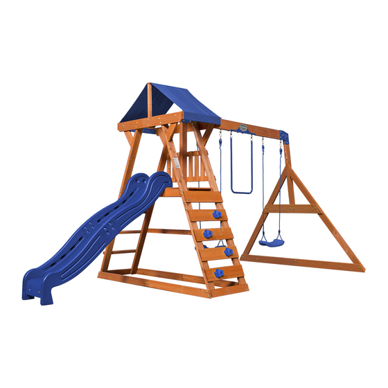
SADDLEBROOK
MANUFACTURED BY:
WOODEN SWING SET
Backyard Discovery
3305 Airport Drive
Pittsburg, KS 66762
Model # 1905016B
Owner's Manual & Assembly Instructions
800-856-4445
WARNING: FOR DOMESTIC USE ONLY.
WARNING
NOT SUITABLE FOR
CHILDREN UNDER 36
MONTHS. SMALL PARTS.
average 2 person assembly time
assembly time may vary based on skill level
For the most up to date assembly manual,
to register your set, or to order replacement parts please visit
www.backyarddiscovery.com
SAVE THIS ASSEMBLY MANUAL FOR FUTURE REFERENCE IN THE EVENT THAT
YOU NEED TO ORDER REPLACEMENT PARTS.
Made in China INS-1905016B-SADDLEBROOK-ENG 09/21/20
Advertisement

Related Manuals for Backyard Discovery 1905016B


Summary of Contents for Backyard Discovery 1905016B
- Page 1 For the most up to date assembly manual, to register your set, or to order replacement parts please visit www.backyarddiscovery.com SAVE THIS ASSEMBLY MANUAL FOR FUTURE REFERENCE IN THE EVENT THAT YOU NEED TO ORDER REPLACEMENT PARTS. Made in China INS-1905016B-SADDLEBROOK-ENG 09/21/20...
- Page 2 INSTALLATION SERVICES AVAILABLE! Need a helping hand? Let our team of professionals handle the installation for you! *Installation services are only available to U.S. customers. With Go Con! gure, we bring you 18 years of experience right to your doorstep. We service a wide array of indoor and outdoor recreation products that most consumers don’t have the time or ability to deliver &...
- Page 3 Owner’s Manual Please Read This Before Starting Assembly MISSING A PART? CALL US BEFORE GOING BACK TO THE STORE e store where you made your purchase does not stock parts for this item. If you have assembly questions or you are missing or have damaged parts, please call 1-800-856-4445 or visit www.backyarddiscovery.com...
- Page 4 All wood carries a ve (5) year pro-rated warranty against rot and decay. Refer to the schedule below for charges associated with replacement of parts under this Limited Warranty. In addition, Backyard Discovery will replace any parts within the rst 30 days from date of purchase found to be missing from or damaged in the original packaging.
- Page 5 Owner’s Manual Operating Instructions and Safety Warnings WARNING: BURN HAZARD • Pay special attention to plastic and metal surfaces as they may be hot enough to cause burns. • Always check the temperature of the product before NOTE: letting your children play on it. •...
- Page 6 Owner’s Manual Please Read This Before Starting Assembly Positioning Your Playcenter Suggested Playground Surfacing • e playcenter is designed to be installed on a level • Do not install home playground equipment over surface by an adult with an adult helper. Place concrete, asphalt, packed earth, grass, carpet, or any in a at area of your yard to minimize ground other hard surface.
- Page 7 Owner’s Manual Please Read This Before Starting Assembly APPENDIX A The following information is from the United States X3.1.3.2 Do not install loose- ll surfacing over hard surfaces such as concrete or asphalt. Consumer Product Safety Commission’s Information X3.1.4 Poured-In-Place Surfaces or Pre-Manufactured Sheet for playground surfacing material;...
- Page 8 Check all moving parts including swing seats, third party person or service to assemble this product. ropes, cables, and chains for wear, rust, or other Backyard Discovery assumes no responsibility or deterioration. Replace as needed. liability for any charge incurred by the Customer for any assembly services’...
- Page 9 About Our Wood Backyard Discovery uses 100% Cedar (C. Lanceolata) wood. Although we take great care in selecting the best quality lumber available, wood is still a product of nature and susceptible to weathering which can change the appearance of your set.
- Page 10 Owner’s Manual Assembly Tips Protrusion Hazard Incorrect Correct If you see exposed threads and your bolt protrudes beyond the T-Nut you may have over tightened the bolt or used incorrect hardware. If you’ve overtightened, remove the bolt and add washers to eliminate the protrusion.
- Page 11 Owner’s Manual Assembly Tips ASSEMBLY TIP: Keep an eye out for these boxes which will contain helpful pictures and information making the assembly process as quick and painless as possible. Sorting Wood When removing the wood from the boxes we recommend arranging them by part number before you begin assembly.
- Page 12 Basic Setup Dimensions Place the set on level ground, not less than 6' - 7" [2 m] from any structure or obstruction such as a fence, garage, house, overhanging branches, laundry lines, or electrical wires. General Information: 28.01 ft Your set has been designed and [8.5 m] engineered for children only and for residential use only.
- Page 13 Tools Required for Installation: (These are the tools that are generally required for assembly of our outdoor products. These tools are not included with the outdoor product purchase.) (Level 24") (Square) (Open End Wrenches 1/2" (Phillips Screw Driver) & 7/16") (Tape Measure) (Claw Hammer) (Rubber Mallet - Optional)
- Page 14 Parts Identification Wood Components (NOT TO SCALE) E2 - FRONT LOWER LEFT FORT LEG - W4L06277 1 3/8"x3 3/8"x42 7/8" (36x86x1090) E3 - FRONT UPPER RIGHT FORT LEG - W4L06280 1 3/8"x3 3/8"x46" (36x86x1168) E4 - FRONT LOWER RIGHT FORT LEG - W4L06381 1 3/8"x3 3/8"x42 7/8"...
- Page 15 Parts Identification Wood Components (NOT TO SCALE) H5 - UPRIGHT BRACE - W4L13751 1"x3 3/8"x6 3/4" (24x86x170) J1 - SAFETY BOARD - W4L06295 1"x2 3/8"x31 5/8" (24x60x802) K1 - ROCKWALL BOARD - W4L04792 5/8"x5 1/4"x23 1/4" (16x134x590) K2 - ROCK BOARD - W4L15016 5/8"...
- Page 16 Parts Identification Wood Components (NOT TO SCALE) N6 - FLOOR BOARD - W4L06286 5/8"x2"x16 1/2" (16x50x418) P1 - LADDER RUNG - W4L06283 1 3/8"x1 3/8"x23 1/4" (36x36x590) P2 - TARP SUPPORT - W4L15017 1 3/8"x1 3/8"x20 1/4" (36x36x514) Q1 - SWING BEAM GROUND BOARD - W4L06304 1"x4 3/8"x45 5/8"...
- Page 17 Parts Identification Hardware (28) - BOLT WH 5/16x1/2 - H100115 (52) - NUT BARREL WH 5/16x7/8 - H100005 (12) - BOLT WH 5/16x1 - H100008 - NUT BARREL WH 5/16x1 1/2 - H100006 - BOLT WH 5/16x1 3/4 - H100011 - NUT BARREL WH 5/16x1 3/4 - H100007 - BOLT WH 5/16x2 - H100012 - LAG SCREW WH 5/16x2 - H100027...
- Page 18 Parts Identification Hardware (13) - SCREW PFH 8x1-1/8" - H100088 (90) (11) - SCREW PFH 8x1-1/2" - H100086 - NUT LOCK 5/16 - H100110 (48) - SCREW PFH 8x2 1/2 - H100090 (20) - T-NUT 1/4 - H100072 (37) - T-NUT 5/16 - H100074 - BOLT WH 1/4x1-3/4 - H101027 - NUT BARREL WH 1/4x5/8 - H100136 - BOLT WH 1/4x1-1/4 - H100142...
- Page 19 Parts Identification Accessories (NOT TO SCALE) - "A" REVISION TAG - A100314 - BLUE HC ROCK #2 - A6P00040 - BLUE HC ROCK #1 - A6P00041 - PICKET PAL - A6P00410 - 90° L-BRACKET - BLK - A4M00555...
- Page 20 Parts Identification Accessories (NOT TO SCALE) - METAL L-BRACKET - BLUE - A4M00938 - GROUND STAKE REBAR - A4M00527 - SLIDE BED 8' BLUE - A6P00358 - TARP .4x580x1736 - A6P00328...
- Page 21 SB2 - SWING BEAM - W4L06299 SB1 - SWING BEAM - W4L06298 - SWING BEAM JOINT BRACKET BLUE - A4M00696 SWING BEAM ASSEMBLY STEP 1 BOLT WH 5/16x4-1/4 BOLT WH 1/4x1-1/2 (4 ) H100166 H100143 NUT BARREL WH NUT BARREL WH 1/4x7/8 5/16x1 1/2 H100140...
- Page 22 Q1 - SWING BEAM GROUND BOARD - W4L07242 1"x4 3/8"x45 5/8" (24x112x1160) SWING BEAM ASSEMBLY STEP 2 NUT BARREL WH WASHER LOCK EXT 5/16x7/8 8x19 H100005 H100030 WASHER LOCK EXT BOLT WH 5/16x1/2 12x19 H100115 H100031 WASHER LOCK EXT 12x19 (2 PLCS) NUT BARREL WH 5/16x7/8 (2 PLCS)
- Page 23 E9 - UPPER ANGLE BRACE BOARD - W4L07239 E10 - LOWER ANGLE BRACE BOARD - W4L07241 1 3/8"x3 3/8"x34 1/8" (36x86x866) 1 3/8"x3 3/8"x46" (36x86x1168) W2 - SWING BEAM SUPPORT - W4L07238 2"x3 3/8"x46" (50x86x1168) SWING BEAM ASSEMBLY STEP 3 NUT BARREL WH 5/16x7/8 (1 PLC) BOLT WH 5/16x4 1/2...
- Page 24 G1 - END SUPPORT - W4L06302 - METAL L-BRACKET - BLUE - A4M00938 1"x5 1/4"x42 7/8" (24x134x1090) SWING BEAM ASSEMBLY STEP 4 BOLT WH 5/16x3 NUT BARREL WH H100016 5/16x1 3/4 BOLT WH 5/16x 3 H100007 (2 PLCS) WASHER LOCK EXT 8x19 (2 PLCS) BOLT WH 5/16x2 H100012...
- Page 25 - 9 1/2" SWING HANGER QUICK LINK - H100099 - SWING BEAM SINGLE CLAMP BLUE - A4M01000 SWING BEAM ASSEMBLY STEP 5 BOLT HEX 5/16x2-3/4 NUT LOCK 5/16 NUT LOCK 5/16 H100047 H100110 (6 PLCS) WASHER FLAT 8x27 (6 PLCS) WASHER FLAT 8x27 LARGE HOLES UP (10)
- Page 26 - SWING BEAM EXT. BRACKET BLUE - LEFT - A4M00511 - SWING BEAM EXT BRACKET BLUE - RIGHT - A4M00512 SWING BEAM ASSEMBLY STEP 6 NUT BARREL WH BOLT WH 5/16x2 1/2 5/16x7/8 H100014 H100005 BOLT WH 5/16x1 3/4 NUT BARREL WH H100011 5/16x1 1/2 H100006...
- Page 27 SWING BEAM ASSEMBLY STEP 7 NUT BARREL WH BOLT WH 5/16x1 3/4 5/16x7/8 H100011 H100005 NUT BARREL WH 5/16x7/8 (2 PLCS) BOLT WH 5/16x1 3/4 (2 PLCS)
- Page 28 M77 - SLIDE BRACE - W4L04711 - SLIDE BED DK.BLUE - A6P00358 5/8"x3 3/8"x14 1/4" (16x86x362) STEP 1 SPEEDY SLIDE ASSEMBLY BOLT WH 5/16x1/2 T-NUT 5/16 SLIDE BED BOTTOM T-NUT 5/16 (2 PLCS) BOLT WH 5/16x1/2 (2 PLCS) USE M77 SLIDE BED SUPPORT AS A TEMPLATE FOR DRILLING BOTTOM HOLE PATTERN IN SLIDE BED.
- Page 29 - SLIDE RAIL BOTTOM LEFT - A6P00177 - SLIDE RAIL TOP LEFT - A6P00176 - SLIDE RAIL TOP RIGHT - A6P00178 - SLIDE RAIL BOTTOM RIGHT - A6P00179 SPEEDY SLIDE ASSEMBLY STEP 2 ● REPEAT ON OTHER SIDE, MAKING A LEFT AND RIGHT ASSEMBLY. BOLT WH 5/16x1/2 NUT BARREL...
- Page 30 M78 - CENTER SLIDE BRACE - W4L04712 5/8"x3 3/8"x14 1/4" (16x86x362) SPEEDY SLIDE ASSEMBLY STEP 3 ● PLACE (1) SLIDE RAIL ASSEMBLY ON A FLAT SURFACE AND BEGIN INSERTING SLIDE BED AT THE BOTTOM OF THE SLIDE RAIL (FIG. 1). HAVE A HELPER BEND THE SLIDE BED TOWARDS THE TOP OF THE SLIDE AND INSERT THE BED INTO THE SLIDE CAVITY.
- Page 31 SPEEDY SLIDE ASSEMBLY STEP 4 ● ONCE THE SLIDE BED, AND SUPPORT BOARDS ARE COMPLETELY IN THE CAVITY AND SUPPORT POCKET, SECURE USING 2-1/2" SCREWS AT EACH OF THE PILOT HOLE LOCATIONS AS SHOWN. ● REPEAT PROCESS FOR OPPOSITE SLIDE RAIL. SCREW PFH 8x2 1/2 (12 PLCS) SCREW PFH...
- Page 32 BOTTOM E2 - FRONT LOWER LEFT FORT LEG - W4L06277 E1 - FRONT UPPER LEFT FORT LEG - W2A02876 1 3/8"x3 3/8"x46" (36x86x1168) 1 3/8"x3 3/8"x42 7/8" (36x86x1090) H5 - UPRIGHT BRACE - W4L13751 - METAL DECK BRACE 380 C/C BLUE - A4M00999 1"x3 3/8"x6 3/4"...
- Page 33 BOTTOM E4 - FRONT LOWER RIGHT FORT LEG - W4L06381 E3 - FRONT UPPER RIGHT FORT LEG - W4L06280 1 3/8"x3 3/8"x42 7/8" (36x86x1090) 1 3/8"x3 3/8"x46" (36x86x1168) - METAL DECK BRACE 380 C/C BLUE - A4M00999 H5 - UPRIGHT BRACE - W4L13751 1"x3 3/8"x6 3/4"...
- Page 34 BOTTOM E6 - REAR LOWER LEFT FORT LEG - W4L06382 E5 - FORT LEG - W4L15011 1 3/8"x3 3/8"x42 7/8" (36x86x1090) 1 3/8" x 3 3/8" x 46" (36 x 86 x 1168) H5 - UPRIGHT BRACE - W4L13751 1"x3 3/8"x6 3/4" (24x86x170) - METAL DECK BRACE 380 C/C BLUE - A4M00999 STEP 3 NUT BARREL WH 5/16x7/8...
- Page 35 BOTTOM E8 - REAR LOWER RIGHT FORT LEG - W4L06380 E7 - FORT LEG - W4L15015 1 3/8"x3 3/8"x42 7/8" (36x86x1090) 1 3/8" x 3 3/8" x 46" (36 x 86 x 1168) H5 - UPRIGHT BRACE - W4L13751 - METAL DECK BRACE 380 C/C BLUE - A4M00999 1"x3 3/8"x6 3/4"...
- Page 36 H1 - UNIVERSAL GROUND BOARD - W4L06276 1"x3 3/8"x42" (24x86x1066) STEP 5 BOLT WH 5/16x1/2 WASHER LOCK EXT 12x19 WASHER (2 PLCS) LOCK EXT 8x19 NUT BARREL WH 5/16x7/8 (2 PLCS) WASHER LOCK EXT 12x19 NUT BARREL WH 5/16x7/8 BOLT WH 5/16x1/2 (2 PLCS) WASHER LOCK EXT 8x19 (2 PLCS)
- Page 37 (1) LEFT SIDE GROUND BOARD ASSEMBLY H2 - FLOOR RAIL - W4L12103 1"x3 3/8"x46" (24x86x1168) (1) FRONT LEFT UPRIGHT ASSEMBLY (1) BACK LEFT UPRIGHT ASSEMBLY STEP 6 INSERT T-NUTS INTO 'H2' BOLT WH 5/16x4-1/4 BOARD BEFORE ASSEMBLY. T-NUT 5/16 WASHER (4 PLCS) T-NUT 5/16 (10)
- Page 38 H1 - UNIVERSAL GROUND BOARD - W4L06276 1"x3 3/8"x42" (24x86x1066) STEP 7 BOLT WH 5/16x1 RIGHT SIDE GROUND BOARD ASSEMBLY WASHER LOCK EXT 8x19 T-NUT 5/16 T-NUT 5/16 WASHER LOCK EXT 8x19 (2 PLCS) (2 PLCS) BOLT WH 5/16x1 (2 PLCS)
-
Page 39: Table Of Contents
H3 - FLOOR RAIL - W4L12104 (1) RIGHT SIDE GROUND BOARD ASSEMBLY 1"x3 3/8"x46" (24x86x1168) NOTE HOLE LOCATION (1) BACK RIGHT UPRIGHT ASSEMBLY (1) FRONT RIGHT UPRIGHT ASSEMBLY STEP 8 INSERT T-NUTS INTO 'H3' BOLT WH 5/16x4-1/4 BOARD BEFORE ASSEMBLY. WASHER T-NUT 5/16 (10) -
Page 40: Step 9
M3 - GROUND BOARD - W4L04794 5/8"x3 3/8"x23 1/4" (16x86x590) STEP 9 SCREW PFH 8x1-1/2" SCREW PFH 8x1-1/2" (8 PLCS) NOTE: ALIGN PILOT HOLES IN M3 GROUND BOARDS WITH PILOT HOLES IN UPRIGHTS. INSTALL AS SHOWN. -
Page 41: Bolt Wh 5/16X4-1/4
W1 - SWINGBEAM SUPPORT - W4L15010 2"x3 3/8"x42 3/8" (50x86x1075) STEP 10 WASHER LOCK EXT 8x19 BOLT WH 5/16x4-1/4 NOTE PROFILE DIRECTION BOLT WH 5/16x4-1/4 (2 PLCS) WASHER LOCK EXT 8x19 (2 PLCS) - Page 42 N6 - FLOOR BOARD - W4L06286 5/8"x2"x16 1/2" (16x50x418) M2 - FLOOR BOARD - W4L06287 (2) FP1 - FLOOR PANEL - W2A01901 5/8"x3 3/8"x16 3/8" (16x86x416) 1 1/4"x19 7/8"x16 7/8" (32x504x430) STEP 11 SCREW PFH (30) 8x1-1/2" SCREW PFH 8x1-1/2" (30 PLCS)
- Page 43 P1 - LADDER RUNG - W4L06283 1 3/8"x1 3/8"x23 1/4" (36x36x590) STEP 12 SCREW PFH 8x2 1/2 (12 PLCS) NOTE: ALIGN PILOT HOLES IN P1 LADDER RUNGS WITH PILOT HOLES IN UPRIGHTS. INSTALL AS SHOWN. SCREW PFH (12) 8x2 1/2...
- Page 44 K1 - ROCKWALL BOARD - W4L04792 5/8"x5 1/4"x23 1/4" (16x134x590) - BLUE HC ROCK #1 - A6P00041 - BLUE HC ROCK #2 - A6P00040 K2 - ROCK BOARD - W4L15016 5/8" x 5 1/4" x 23 1/4" (16 x 134 x 590) STEP 13 BLUE HC ROCK #2 (SEE BELOW)
-
Page 45: Nut Barrel Wh 5/16X7/8
H4 - ANGLE BRACE - W4L06561 L1 - TOP RAIL - W4L15012 1"x3 3/8"x14" (24x86x355) 5/8" x 4 3/8" x 44 7/8" (16 x 112 x 1140) - 90° L-BRACKET - BLK - A4M00555 STEP 14 WASHER LOCK EXT 8x19 (8 PLCS) LAG SCREW BOLT WH... - Page 46 N3 - TARP SUPPORT - W4L15018 F1 - TARP SUPPORT - W4L15014 5/8"x2 3/8"x23 1/4" (16x60x590) 1 3/8"x2"x13 1/4" (36x50x335) - 90° L-BRACKET - BLK - A4M00555 P2 - TARP SUPPORT - W4L15017 M4 - TARP BOARD - W4L15013 1 3/8"x1 3/8"x20 1/4" (36x36x514) 5/8"...
- Page 47 - TARP .4x580x1736 - A6P00328 STEP 16 ADJUST OVERLAP SO TARP IS TIGHT SCREW PWH 8x5/8 SCREW PWH 8x5/8 (6 PLCS) (3 LEFT, 3 RIGHT) SCREW PWH 8x5/8 (3 PLC) 1.60 SPACING TARP .4x580x1736 (1 PLC)
- Page 48 N1 - WALL RAIL - W4L06288 N2 - WALL RAIL - W4L06289 5/8"x2 3/8"x39 7/8" (16x60x1012) 5/8"x2 3/8"x29 5/8" (16x60x754) STEP 17 LAG SCREW WASHER WH 5/16x2 LOCK EXT 8x19 LAG SCREW WH 5/16x2 (6 PLCS) WASHER LOCK EXT 8x19 (6 PLCS)
- Page 49 N5 - WALL BOARD - W4L06297 N4 - WALL BOARD - W4L06296 5/8"x2 3/8"x14 5/8" (16x60x372) 5/8"x2 3/8"x14 5/8" (16x60x372) STEP 18 SCREW PFH (12) 8x1-1/8" SCREW PFH 8x1-1/8" 1 5/8" (12 PLCS) (6 SPCS)
- Page 50 J1 - SAFETY BOARD - W4L06295 M5 - BOARD - W4L11800 1"x2 3/8"x31 5/8" (24x60x802) 5/8"x3 3/8"x24 1/8" (16x86x612) STEP 19 BOLT WH 5/16x1 WASHER LOCK EXT 8x19 INSTALL T- NUT FIRST T-NUT 5/16 SCREW PFH 8x1-1/2" SCREW PFH 8x1-1/2" (2 PLCS) T-NUT 5/16 (1 PLC)
- Page 51 (1) SAFETY SWING RAIL ASSEMBLY STEP 20 SCREW PFH 8x2 1/2 SCREW PFH 8x1-1/2" SCREW PFH 8x2 1/2 (4 PLCS) SCREW PFH 8x1-1/2" (2 PLCS) SAFETY SWING RAIL ASSEMBLY...
- Page 52 - "A" REVISION TAG - A100314 EA - HAND GRIP BLUE PLASTIC - A6P00314 STEP 21 BOLT WH 1/4x1-3/4 WASHER T-NUT 1/4 LOCK EXT 6x15 SCREW PWH 8x5/8 BOLT WH 1/4x1-3/4 (4 PLCS) WASHER LOCK EXT 6x15 SCREW PWH 8x5/8 (4 PLCS) (2 PLCS) "A"...
- Page 53 (1) SWING BEAM ASSEMBLY STEP 22 WASHER NUT LOCK 5/16 FLAT 8x27 (2 PLCS) WASHER FLAT 8x27 (4 PLCS) NUT LOCK BOLT HEX 5/16x2-3/4 5/16 (2 PLCS) BOLT HEX 5/16x2-3/4 TIGHTEN NOW...
- Page 54 - MOLDED SWING SEAT - BLUE/BLUE 461c-c - A6P00329 STEP 23 NOTE: TIGHTEN QUICK WHEN HANGING YOUR SWINGS IT IS LINK RECOMMENDED THAT THE BOTTOM OF THE SWING SEAT, WHEN SITTING ON IT, IS LOCATED NO LOWER THAN (35 cm) 13 7/8 INCHES FROM THE GROUND.
- Page 55 - METAL TRAPEZE BLUE - A4M00697 STEP 24 TIGHTEN QUICK LINK INSERT CHAIN INTO QUICK LINK METAL TRAPEZE BLUE (1 PLC)
- Page 56 (1) SPEEDY SLIDE B-L (4 PCS) - NARROW STEP 25 BOLT WH 5/16x1/2 T-NUT 5/16 BOLT WH 5/16x1/2 (2 PLCS) T-NUT 5/16 (2 PLCS) 2 5/8 in [67 mm] CENTER SLIDE AND ALIGN TO DIMENSION. DRILL 7/16" (11mm) HOLES AND INSTALL HARDWARE DRILLING PATTERN...
- Page 57 - GROUND STAKE REBAR - A4M00527 Anchoring Instructions STEP 26 TAP IN GROUND STAKES AT AN APPROXIMATE 45° ANGLE AT THE LOCATIONS SHOWN. BOLT WH 5/16x1/2 GROUND STAKE INSTALLATION ON THE SWING BEAM GROUND BOARD. BOLT WH 5/16x1/2 WASHER LOCK EXT 12x19 (2 PLCS) (2 PLCS) WASHER...
Need help?
Do you have a question about the 1905016B and is the answer not in the manual?
Questions and answers