Advertisement
Table of Contents
chipKIT™ DP32™ Board Reference Manual
Revised October 9, 2015
This manual applies to the chipKIT DP32 rev. C
Overview
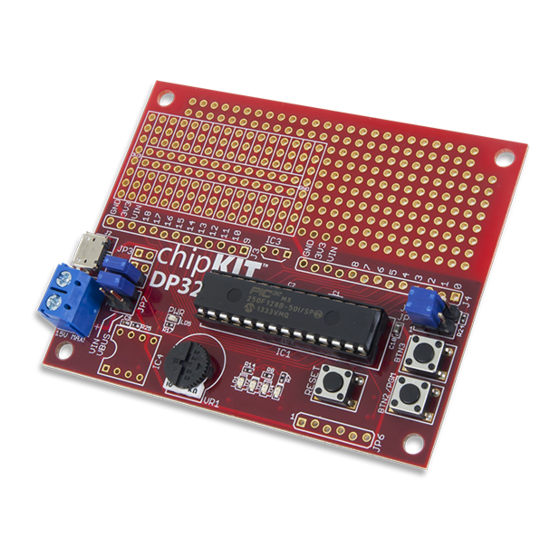
The chipKIT DP32 is an MPIDE compatible prototyping and project development board from Digilent. It combines
the power of the Microchip® PIC32MX250F128B with a wire wrap prototyping area and provision for an EEPROM
non-volatile memory. The chipKIT DP32 has many on board features, including an analog temperature sensor, a
potentiometer, buttons, and LEDs. The mounting hole footprint on the board is designed to fit in the Hammond
1591XXSSBK project box.
The chipKIT DP32 Board.
The DP32 takes advantage of the powerful PIC32MX250F128B microcontroller. This microcontroller features a 32-
bit MIPS processor core running at 40 MHz, 128K of flash program memory, and 32K of SRAM data memory. The
PIC32MX250F128B is suitable for building projects directly on the board, utilizing the provided prototyping area,
but it can also be used as a PIC32MX250F128B programmer to program the microcontrollers for inclusion in
custom built projects.
The DP32 can be programmed using the Multi-Platform Integrated Development Environment (MPIDE), an
environment based on the open source Arduino™ IDE, modified to support the PIC32 microcontroller. The board
provides everything needed to start developing embedded applications using the MPIDE.
The DP32 is also fully compatible with the advanced Microchip MPLAB® IDE and MPLAB® X IDE. To develop
embedded applications using MPLAB, a separate In Circuit Serial Programmer (ICSP) such as the Digilent chipKIT
PGM or the Microchip PICkit3™, is required.
DOC#: 502-280
Other product and company names mentioned may be trademarks of their respective owners.
Microchip PIC32MX250F128B
microcontroller (40/50 MHz 32-bit MIPS,
128K Flash, 32K SRAM)
5 – 12 Volt recommended operating
voltage
19 available I/O pins
Up to 9 analog inputs
1 Potentiometer connected to an analog
input
Four user LEDs
Two user push button
Wire wrap prototype area
Provision for an SPI EEPROM and an analog
temperature sensor
Mounting Hole compatible with Hammond
1591XXSSBK project box
Copyright Digilent, Inc. All rights reserved.
1300 Henley Court
Pullman, WA 99163
509.334.6306
www.digilentinc.com
Page 1 of 9
Advertisement
Table of Contents

Related Manuals for Digilent chipKIT DP32


Summary of Contents for Digilent chipKIT DP32
- Page 1 This manual applies to the chipKIT DP32 rev. C Overview The chipKIT DP32 is an MPIDE compatible prototyping and project development board from Digilent. It combines the power of the Microchip® PIC32MX250F128B with a wire wrap prototyping area and provision for an EEPROM non-volatile memory.
-
Page 2: Functional Description
2. JP6 – Microchip Debug Tool Connector: This connector is used to connect ICSP tools, such as the PICkit™3 or Digilent chipKIT PGM. This allows the DP32 board to be used as a traditional microcontroller development board using the Microchip MPLAB®... - Page 3 VCC3V3 of the device, pin two (center pin) is for the A0/pin 6 pin of the device, and pin three is for the ground pin (chipKIT pin 6). Copyright Digilent, Inc. All rights reserved. Page 3 of 9 Other product and company names mentioned may be trademarks of their respective owners.
- Page 4 The unloaded connector JP6 on the right side of the board is used to connect to a Microchip development tool, such as the PICkit3 or the Digilent chipKIT PGM. The holes for JP6 are staggered so that a standard 100-mil spaced 6-pin header can be press fit to the board without the need to solder it in place.
-
Page 5: Power Supply
Using the Microchip development tools to program the DP32 board will cause the boot loader to be erased. To use the board with the MPIDE again, it is necessary to program the bootloader back onto the board. The boot loader image can be downloaded from the DP32 product page on the Digilent website. chipKIT DP32 Jumper Settings USBID Connect (USB OTG) Loaded: USBID is connected to Digital I/O pin 0 (RB5) and is usable by the microcontroller. -
Page 6: Input/Output Connections
An advanced feature of the PIC32MX1xx/2xx family of microcontrollers is the ability to re-map the locations of peripheral devices. MPIDE does the default mapping. Copyright Digilent, Inc. All rights reserved. Page 6 of 9 Other product and company names mentioned may be trademarks of their respective owners. - Page 7 PIC32 Microcontroller. The second SPI is implemented as Pin 14 (SS), Pin 2 (MOSI), Pin 13 (MISO), and Pin 8 (SCK). Copyright Digilent, Inc. All rights reserved. Page 7 of 9 Other product and company names mentioned may be trademarks of their respective owners.
-
Page 8: Appendix A: Pinout Tables
8 MHz Clock In OSC2/CLKO/RPA3/PMA0/RA3 8 MHz Clock Out SOSCI/RPB4/RB4 BTN4 SOSCO/RPA4/T1CK/CTED9/PMA1/RA4 IC4 – Serial In *Pins are 5v Tolerant Copyright Digilent, Inc. All rights reserved. Page 8 of 9 Other product and company names mentioned may be trademarks of their respective owners. - Page 9 IC4 – Serial Clock 8/A2 RB15 AN9/C3INA/RPB15/SCK2/CTED6/PMCS1/RB15 Dial Pot – Pin A2 AVSS AVDD *Pins are 5V Tolerant Copyright Digilent, Inc. All rights reserved. Page 9 of 9 Other product and company names mentioned may be trademarks of their respective owners.
- Page 10 Mouser Electronics Authorized Distributor Click to View Pricing, Inventory, Delivery & Lifecycle Information: Digilent 410-280P-KIT 410-280...
Need help?
Do you have a question about the chipKIT DP32 and is the answer not in the manual?
Questions and answers