Advertisement
Quick Links
chipKIT™ uC32™ Board Reference Manual
Revised December 29, 2014
This manual applies to the uC32 rev. B
Overview
The chipKIT uC32 is based on the popular Arduino™ open-source hardware prototyping platform and adds the
performance of the Microchip® PIC32 microcontroller. The uC32 is easy to use and suitable for both beginners and
advanced users experimenting with electronics and embedded control systems. The uC32 is the same form factor
as the Arduino Uno board and is compatible with Arduino shields. It features a USB serial port interface for
connection to the IDE and can be powered via USB or an external power supply. The uC32 board takes advantage
of the powerful PIC32MX340F512 microcontroller, which features a 32-bit MIPS processor core running at 80 MHz,
512K of flash program memory, and 32K of SRAM data memory.
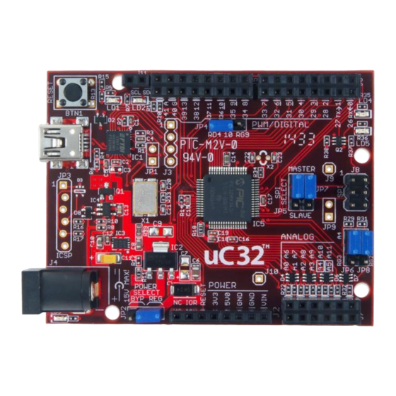
The chipKIT uC32 board.
The uC32 can be programmed using the Multi-Platform Integrated Development Environment (MPIDE), an
environment based on the original Arduino IDE modified to support PIC32. It contains everything needed to start
developing embedded applications. In addition, the uC32 is fully compatible with the advanced Microchip MPLAB®
IDE and the PICkit™ 3 in-system programmer/debugger.
The uC32 provides 43 I/O pins that support a number of peripheral functions, such as UART, SPI, and I
pulse width modulated outputs. Twelve of the I/O pins can be used as analog inputs or as digital inputs and
outputs.
DOC#: 502-254
Other product and company names mentioned may be trademarks of their respective owners.
Features include:
Copyright Digilent, Inc. All rights reserved.
1300 Henley Court
Pullman, WA 99163
www.digilentinc.com
Microchip PIC32MX340F512H
microcontroller (80 MHz 32-bit MIPS,
512K Flash, 32K SRAM)
Compatible with many existing Arduino
code samples and other resources
Arduino Uno form factor
Compatible with many Arduino shields
43 available I/O pins
Two user LEDs
PC connection uses a USB A > mini B cable
(not included)
12 analog inputs
3.3V operating voltage
80 MHz operating frequency
75mA typical operating current
7V to 15V input voltage (recommended)
20V input voltage (maximum)
0V to 3.3V analog input voltage range
+/-18mA DC current per pin
509.334.6306
2
C ports and
Page 1 of 17
Advertisement

Subscribe to Our Youtube Channel
Related Manuals for Digilent chipKIT uC32


Summary of Contents for Digilent chipKIT uC32
- Page 1 This manual applies to the uC32 rev. B Overview The chipKIT uC32 is based on the popular Arduino™ open-source hardware prototyping platform and adds the performance of the Microchip® PIC32 microcontroller. The uC32 is easy to use and suitable for both beginners and advanced users experimenting with electronics and embedded control systems.
- Page 2 4. Power Supply – 3.3V Regulator Voltage regulator for the 3.3V power supply. This power supply can provide up to 500mA of current. Copyright Digilent, Inc. All rights reserved. Page 2 of 17 Other product and company names mentioned may be trademarks of their respective owners.
- Page 3 JP6 and JP8 are in the RG3 and RG2 position, the I C signals will be tied to pins A4 and A5 on J7. Copyright Digilent, Inc. All rights reserved. Page 3 of 17 Other product and company names mentioned may be trademarks of their respective owners.
- Page 4 Arduino community. In order to maintain compatibility with existing hardware and software, additional jumpers and row headers are provided. This document describes the functionality of the jumpers listed in Fig. 1 below. Figure 1. chipKIT uC32 jumpers. Copyright Digilent, Inc. All rights reserved. Page 4 of 17...
- Page 5 A4 and A5 are configured to be used as I as analog inputs. communication lines (A4 – SDA, A5 – SCL ). Copyright Digilent, Inc. All rights reserved. Page 5 of 17 Other product and company names mentioned may be trademarks of their respective owners.
-
Page 6: Power Supply
5V output. The absolute maximum input voltage of both the NCP1117 and the LM1117 is 20V. The recommended maximum operating voltage is 15V. Copyright Digilent, Inc. All rights reserved. Page 6 of 17 Other product and company names mentioned may be trademarks of their respective owners. - Page 7 It can also be used to power the uC32 board from the shield instead of from the external power connector. Copyright Digilent, Inc. All rights reserved. Page 7 of 17 Other product and company names mentioned may be trademarks of their respective owners.
-
Page 8: Input/Output Connections
The inner row of pins are A6-A11. These pins are also assigned digital pin numbers: A0-A5 are digital pins 14-19, and A6-A11 are 20-25. Copyright Digilent, Inc. All rights reserved. Page 8 of 17 Other product and company names mentioned may be trademarks of their respective owners. - Page 9 RESET: The PIC32 microcontroller is reset by bringing its MCLR pin low. The MCLR pin is connected to the P32_RST net on the circuit board. Copyright Digilent, Inc. All rights reserved. Page 9 of 17 Other product and company names mentioned may be trademarks of their respective owners.
- Page 10 Using the Microchip development tools to program the uC32 board will cause the boot loader to be erased. To use the board with the MPIDE again, it is necessary to program the boot loader back onto the board. The boot loader image can be downloaded from the Digilent Uno32 product page. Copyright Digilent, Inc. All rights reserved.
-
Page 11: Pinout Tables
Also on J8-3, User J5-11 SCK2/PMA5/CN8/RG6 LED LD4r 14/A0 J7-01 C2IN-/AN2/SS1/CN4/RB2 15/A1 J7-03 C1IN-/AN4/CN6/RB4 16/A2 J7-05 U2CTS/C1OUT/AN8/RB8 Copyright Digilent, Inc. All rights reserved. Page 11 of 17 Other product and company names mentioned may be trademarks of their respective owners. - Page 12 J5-05 PMA2/SS2/CN11/RG9 also on J8-6 J11-1, J7-09 SDA1/RG3 Selected by JP6 J11-2, J7-11 SCL1/RG2 Selected by JP8 Copyright Digilent, Inc. All rights reserved. Page 12 of 17 Other product and company names mentioned may be trademarks of their respective owners.
- Page 13 J6-07 OC1/RD0 J6-08 PMD3/RE3 J6-09 J6-10 PMD4/RE4 J6-11 OC2/RD1 J6-12 PMD5/RE5 J6-13 OC3/RD2 J6-14 PMD6/RE6 J6-15 IC2/U1CTS/INT2/RD9 Copyright Digilent, Inc. All rights reserved. Page 13 of 17 Other product and company names mentioned may be trademarks of their respective owners.
- Page 14 Selected by JP4, also on J5-05 SS2/PMA2/CN11/RG9 J8-6 J7-03 A07/21 C1IN+/AN5/CN7/RB5 J7-03 A01/15 C1IN-/AN4/CN6/RB4 J7-02 A06/20 C2IN+/AN3/CN5/RB3 Copyright Digilent, Inc. All rights reserved. Page 14 of 17 Other product and company names mentioned may be trademarks of their respective owners.
- Page 15 X1, system clock OSC1/CLKI/RC12 oscillator X1, system clock OSC2/CLKO/RC15 oscillator J6-05 IC1/RTCC/INT1/RD8 J6-15 IC2/U1CTS/INT2/RD9 J5-01 IC3/PMCS2/PMA15/INT3/RD10 J5-04 IC4/PMCS1/PMA14/INT4/RD11 Copyright Digilent, Inc. All rights reserved. Page 15 of 17 Other product and company names mentioned may be trademarks of their respective owners.
- Page 16 CHIPKIT and the CHIPKIT Logo are trademarks or registered trademarks of Microchip Technology Incorporated in the U.S. and other countries, and are used under license. Copyright Digilent, Inc. All rights reserved. Page 16 of 17 Other product and company names mentioned may be trademarks of their respective owners.
-
Page 17: Declaration Of Conformity
Clint Cole_______ Location: _Pullman, WA______ Signature: Date: _October 16, 2012___ Full Name (print): Clint Cole Title: President_________ Copyright Digilent, Inc. All rights reserved. Page 17 of 17 Other product and company names mentioned may be trademarks of their respective owners. - Page 18 Mouser Electronics Authorized Distributor Click to View Pricing, Inventory, Delivery & Lifecycle Information: Digilent 410-254P-KIT 410-254...
Need help?
Do you have a question about the chipKIT uC32 and is the answer not in the manual?
Questions and answers