Table of Contents
Advertisement
Quick Links
12/21/2018
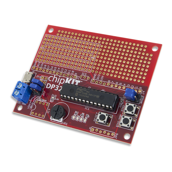
chipKIT DP32 Reference Manual
(https://reference.digilentinc.com/_detail/chipkit_dp32/16025616573_29ae205bbe_z.jpg?id=chipkit_dp32%3Arefmanual)
Revision History
Revised March, 2015
This manual primarily applies to Rev C, as found on the underside of the board next to the white bar-coded box. Rev C is a major change
from Rev B, so differences will be noted where appropriate.
Overview
The chipKIT DP32 is an MPIDE compatible prototyping and project development board from Digilent. It combines the power of the
Microchip® PIC32MX250F128B 28-pin DIP with a wire wrap prototyping area, provision for an EEPROM () non-volatile memory, and
analog temperature sensor, a potentiometer, buttons and LEDs in a single board. The mounting hole footprint on the board is designed
to fit in the Hammond 1591XXSSBK project box.
The DP32 takes advantage of the powerful PIC32MX250F128B microcontroller. This microcontroller features a 32-bit MIPS processor
core running at 40 MHz (), 128K of flash program memory and 32K of SRAM data memory. It is suitable for building projects directly
on the board utilizing the provided prototyping area, but it can also be used as a device programmer to program the microcontrollers for
inclusion in custom built projects.
The DP32 can be programmed using the Multi-Platform Integrated Development Environment, MPIDE, an environment based on the
open source Arduino™ IDE modified to support the PIC32 microcontroller. The board provides everything needed to start developing
embedded applications using the MPIDE.
The DP32 is also fully compatible with the advanced Microchip® MPLAB X® IDE. To develop embedded applications using MPLAB
X, a separate device programmer/debugger, such as the Digilent chipKIT PGM or the Microchip PICkit3™ is required.
Features Include:
Microchip PIC32MX250F128B 28-pin DIP microcontroller (40/50 MHz () 32-bit MIPS, 128K Flash, 32K SRAM)
5 – 12 Volt recommended operating voltage
https://reference.digilentinc.com/chipkit_dp32/refmanual
chipKIT DP32 Reference Manual [Reference.Digilentinc]
1/17
Advertisement
Table of Contents

Subscribe to Our Youtube Channel
Related Manuals for Digilent chipKIT DP32


Summary of Contents for Digilent chipKIT DP32
- Page 1 Rev B, so differences will be noted where appropriate. Overview The chipKIT DP32 is an MPIDE compatible prototyping and project development board from Digilent. It combines the power of the Microchip® PIC32MX250F128B 28-pin DIP with a wire wrap prototyping area, provision for an EEPROM () non-volatile memory, and analog temperature sensor, a potentiometer, buttons and LEDs in a single board.
-
Page 2: Functional Description
12/21/2018 chipKIT DP32 Reference Manual [Reference.Digilentinc] 19 available I/O pins Up to 9 analog inputs 1 Potentiometer connected to an analog input Four user LEDs Two user push button Wirewrap prototype area Provision for an SPI EEPROM () and an analog temperature sensor... - Page 3 12/21/2018 chipKIT DP32 Reference Manual [Reference.Digilentinc] The DP32 has the following hardware features: 1. J3 – Digital and Analog I/O Connector #2 The set of Digital I/Os with chipKIT numbers 9 through 18 and Analog pins A3-A8. The holes are slightly offset to allow for friction fitting of headers. See the Pinout Diagram and Pinout Table for more details.
- Page 4 11. JP6 – Microchip Debug Tool Connector This connector is used to connect Microchip and Digilent programmer/debugger tools, such as the PICkit™3 or Digilent chipKIT PGM. This allows the DP32 board to be used as a traditional microcontroller development board using the Microchip MPLAB® IDE. Note that the square pad is pin 1.
- Page 5 12/21/2018 chipKIT DP32 Reference Manual [Reference.Digilentinc] 3 Programming the chipKIT DP32 3.1 MPIDE Development Tool The DP32 uses the PIC32MX250F128B onboard USB peripheral to program the microcontroller with the MPIDE environment. This requires a driver to be installed to accommodate this programing solution. The driver file is called Stk500v2.inf and is available in the drivers folder in the MPIDE distribution.
- Page 6 12/21/2018 chipKIT DP32 Reference Manual [Reference.Digilentinc] 4. Open that application and click “Install Drivers”. You may need to allow admin permission for it to complete. 5. Once the drivers are installed, close the windows. Open MPIDE, connect the board with the USB cable, and allow Windows to find and install the correct drivers.
- Page 7 The unloaded connector JP6 on the right side of the board is used to connect to a Microchip development tool, such as the PICkit3™ or the Digilent chipKIT PGM. The holes for JP6 are staggered so that a standard 100-mil spaced 6-pin header can be press fit to the board without the need to solder it in place.
- Page 8 12/21/2018 chipKIT DP32 Reference Manual [Reference.Digilentinc] 6. Name the project whatever you wish, then click “Browse” to store it in whichever file you wish. Default names will be auto- populated. 7. Check the box labeled “Set as main project”, then click “Finish”...
- Page 9 3.4 Programming Additional ICs A unique feature of the DP32 from the rest of the Digilent line of chipKIT boards is that the PIC32 microcontroller installed on the board is a removable, 28-pin DIP IC. This allows for lots of flexibility in building embedded projects since you can program the IC with the board, remove it, and then embed it into a stand-alone application without the need to purchase an additional board (additional circuitry is required to embed the IC into stand alone projects).
-
Page 10: Power Supply
12/21/2018 chipKIT DP32 Reference Manual [Reference.Digilentinc] JP4/JP5 pullups/pulldowns Default configuration is with the shorting blocks loaded on pins 1 and 2, which results in pullup configuration. Shorting pins 2 and 3 results in pulldown operation. Users may choose to remove shorting blocks entirely if no pullup/pulldown settings are desired. -
Page 11: Input/Output Connections
12/21/2018 chipKIT DP32 Reference Manual [Reference.Digilentinc] Only MIPDE pin numbers 0 - 3 on the PIC32 microcontroller are 5V tolerant. All other pins are 3.3V tolerant only. To provide 5V tolerance on those pins, you will have to add clamping diodes and current limiting resistors to those pins. Please check the Pinout Diagram or Pinout Table to confirm 5V tolerant pins. -
Page 12: Appendix A: Pinout Diagram
12/21/2018 chipKIT DP32 Reference Manual [Reference.Digilentinc] Change Notice Pins All change notice pins are matched with their chipKIT pin numbers (e.g. CN0 is associated with Pin 0). There is a change notice pin for each I/O pin. UART Pin 14 (U1TX), Pin 6 (U1RX), Pin 7 (U2TX) and Pin 10 (U2RX) are used to implement UART peripheral controls. Unlike other chipKIT boards, the USB Serial communication is not implemented using a UART controller. - Page 13 12/21/2018 chipKIT DP32 Reference Manual [Reference.Digilentinc] chipKIT Pin PIC32 register PIC32 Signal Notes RB11 PGEC2/RPB11/D- USB Data- 6/A0 RB13 AN11/RPB13/CTPLS/PMRD Analog Temp 7/A1 RB14 CVREF/AN10/C3INB/RPB14/VBUSON/SCK1/CTED5 IC4 – Serial Clock 8/A2 RB15 AN9/C3INA/RPB15/SCK2/CTED6/PMCS1 Dial Pot – Pin 9/A3 PGED3/VREF+/CVREF+/AN0/C3INC/RPA0/CTED1/PMD7 IC4 – Chip...
-
Page 14: Appendix C: Pinout Table By Socket Pin
12/21/2018 chipKIT DP32 Reference Manual [Reference.Digilentinc] For a more detailed explanation of the functionality of each pin and the PIC32 architecture, please see the datasheet from Microchip. http://ww1.microchip.com/downloads/en/DeviceDoc/60001168F.pdf (http://ww1.microchip.com/downloads/en/DeviceDoc/60001168F.pdf) Appendix C: Pinout Table by Socket Pin Socket chipKIT Connector... -
Page 15: Appendix D: Schematic
12/21/2018 chipKIT DP32 Reference Manual [Reference.Digilentinc] Socket chipKIT Connector Pin # Pin # Pin # PIC32 Signal Notes GND () VCAP RB10 PGED2/RPB10/D+/CTED11/RB10 Data+ RB11 PGEC2/RPB11/D-/RB11 Data- VUSB3V3 6/A0 RB13 AN11/RPB13/CTPLS/PMRD/RB13 Analog Temp Pin A0 7/A1 RB14 CVREF/AN10/C3INB/RPB14/VBUSON/SCK1/CTED5/RB14 IC4 –... - Page 16 12/21/2018 chipKIT DP32 Reference Manual [Reference.Digilentinc] Jobs distributors/) (https://store.digilentinc.com/ Internships (https://store.digilentinc.com/ Connect With Us (https://twitter.com/digilentinc) (https://www.facebook.com/Digilent) (https://www.youtube.com/user/DigilentInc) (https://instagram.com/digilentinc) (https://github.com/digilent) (https://www.reddit.com/r/digilent) (https://www.linkedin.com/company/1454013) (https://www.flickr.com/photos/127815101@N07) https://reference.digilentinc.com/chipkit_dp32/refmanual 16/17...
- Page 17 12/21/2018 chipKIT DP32 Reference Manual [Reference.Digilentinc] https://reference.digilentinc.com/chipkit_dp32/refmanual 17/17...
Need help?
Do you have a question about the chipKIT DP32 and is the answer not in the manual?
Questions and answers