ESAB Aristo U82 Instruction Manual
Hide thumbs
Also See for Aristo U82:
- Instruction manual (96 pages) ,
- Installation instruction (2 pages) ,
- Instruction manual (84 pages)

Related Manuals for ESAB Aristo U82


Summary of Contents for ESAB Aristo U82
- Page 1 Aristo® Instruction manual Valid from program version 1.15A 0460 896 274 GB 20130902...
-
Page 2: Table Of Contents
TABLE OF CONTENTS SAFETY ........................ 5 INTRODUCTION ....................7 Control panel Aristo U82 ..................7 2.1.1 Keys and knobs....................7 Location ........................ 8 USB connection ....................8 2.3.1 Insert the USB memory..................9 First step – choice of language ................9 Display ........................ - Page 3 AVC feeder ....................... 56 9.3.6 Release pulse ....................56 MMA defaults...................... 56 Fast mode soft keys................... 56 Double start sources ..................57 Panel remote enable ..................57 WF supervision ....................57 Auto save mode ....................57 0460 896 274 © ESAB AB 2013...
- Page 4 10.10 User accounts ....................77 10.11 Unit information ....................78 11 ORDERING SPARE PARTS ................79 MENU STRUCTURE....................80 WIRE AND GAS DIMENSIONS.................86 ORDERING NUMBERS .....................93 ACCESSORIES ......................94 Rights reserved to alter specifications without notice. 0460 896 274 © ESAB AB 2013...
-
Page 5: Safety
1 SAFETY SAFETY NOTE! The unit is tested by ESAB in a general set-up. The responsibility for safety and function, of the specific set-up, lies with the integrator. Users of ESAB equipment have the ultimate responsibility for ensuring that anyone who works on or near the equipment observes all the relevant safety precautions. - Page 6 As the person responsible for the equipment, it is your responsibility to obtain information on approved collection stations. For further information contact the nearest ESAB dealer. 0460 896 274 - 6 - © ESAB AB 2013...
-
Page 7: Introduction
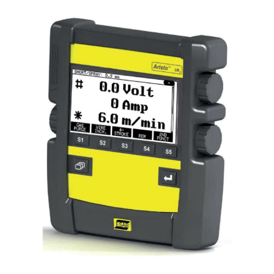
Differences in the panel function may occur, depending on in which product it is installed. Control panel Aristo U82 The control panel is supplied with a mounting bracket with screws and an English instruction manual. A 1.2 m cable is mounted on to the panel. A USB memory and an extension cable are available as accessories, see the "ACCESSORIES"... -
Page 8: Location
Certain USB memories may not work with this equipment. We recommend using USB memories from a reputable supplier. ESAB assumes no responsibility for any damage caused as a consequence of the incorrect use of a USB memory. -
Page 9: Insert The Usb Memory
The control panel is set to English on delivery. To select your language, proceed as follows. Press MENU to come to the main menu. Using the left-hand knob, position the cursor on the CONFIGURATION row. Press ENTER 0460 896 274 - 9 - © ESAB AB 2013... -
Page 10: Display
The control panel's cursor is presented as a shaded field around the text, with the selected text turning white. The selection is displayed in the instruction manual with bold text. 0460 896 274 - 10 - © ESAB AB 2013... -
Page 11: Symbols In The Display
Select the plus/minus knob marked # to increase or decrease a parameter value. Measured motor current Select the plus/minus knob marked * to increase or decrease a parameter value. Editing mode, editing memory position 0460 896 274 - 11 - © ESAB AB 2013... -
Page 12: General Information About Settings
Pressing QUIT entails moving back to the previous menu or screen. key is called ENTER in this manual. • Pressing ENTER entails the execution of a selected choice in a menu or a list. 0460 896 274 - 12 - © ESAB AB 2013... -
Page 13: Menus
Start-up screen Main menu In the MAIN MENU, you can change welding process, welding method, wire type, etc. From this menu you can proceed to all other sub-menus. 0460 896 274 - 13 - © ESAB AB 2013... -
Page 14: Configuration Menu
In the CONFIGURATION menu you can change language, alter other basic settings, unit of measurement etc. 3.1.2 Tools menu In the TOOLS menu you can transfer files, view quality and production statistics, error logs, etc. 0460 896 274 - 14 - © ESAB AB 2013... -
Page 15: Weld Data Setting Menu
In the WELD DATA SETTING menu you can alter various welding parameters. The menu has different appearances depending on which welding process is selected. The example shows MIG/MAG welding with short-/sprayarc. 0460 896 274 - 15 - © ESAB AB 2013... -
Page 16: Measure
TIP:When pulsing, you can select whether the voltage value is to be displayed as an average value or a peak value. This setting can be adjusted under MIG/MAG defaults, see the "MIG/MAG defaults" section. 0460 896 274 - 16 - © ESAB AB 2013... -
Page 17: Weld Data Memory Meny
Configuration menu. The number of the selected memory position is displayed in the top right corner. For further information, see the “Fast mode soft keys” section. 0460 896 274 - 17 - © ESAB AB 2013... -
Page 18: Mig/Mag Welding
“Hot start” time 0 - 10 s 0.1 s “Hot start” wire feed Complete wire feed 0.1 m/min range “Touch sense” 10 - 16 A Soft start OFF or ON 0460 896 274 - 18 - © ESAB AB 2013... -
Page 19: Mig/Mag Welding With Pulsing
“Hot start” OFF or ON “Hot start” time 0 - 10 s 0.1 s “Hot start” wire feed Complete wire feed 0.1 m/min range “Touch sense” 10 - 16 A 0460 896 274 - 19 - © ESAB AB 2013... -
Page 20: Mig/Mag Welding With Superpulse, Primary/Secondary, Short-/Sprayarc/Pulsing
0 - 100% Pulse current** 100 - 650 A Pulse time 1.7 - 25.5 ms 0.1 ms Pulse frequency 16 - 312 Hz 2 Hz Background current 4 - 300 A 0460 896 274 - 20 - © ESAB AB 2013... - Page 21 **) Minimal background current and pulse current are dependent on which machine type is used. ***) The synergic line on delivery: solid wire (ER70S), shielding gas CO2 with wire 1.2 mm. ****) Adjusted in the configuration menu MIG/MAG basic settings. 0460 896 274 - 21 - © ESAB AB 2013...
-
Page 22: Function Explanations For Settings
The lower of the two current values in the event of pulsed current. Background current is set in the weld data setting menu with the synergy function switched off. Only applies to MIG/MAG welding with pulsing. 0460 896 274 - 22 - © ESAB AB 2013... - Page 23 Ki is set in the weld data setting menu → internal constants with the synergy function switched off. Only applies to MIG/MAG welding with pulsing. 0460 896 274 - 23 - © ESAB AB 2013...
- Page 24 It is possible to order different packages of synergic lines, although these must be installed by an authorised ESAB service engineer. For the creation of own synergic lines, see the "User defined synergic data" section. Activation of the synergy takes place in the weld data setting menu.
- Page 25 If the settings for continuous welding are lowered below the set final values, they will also lower the final values. The final parameter values will not increase again if the setting for continuous welding is increased. 0460 896 274 - 25 - © ESAB AB 2013...
- Page 26 Setting limits and measure limits In limits, a limit number is selected. For settings, see the “Edit setting limits” and “Edit measure limits” sections. Limits are activated in the weld data setting menu. 0460 896 274 - 26 - © ESAB AB 2013...
-
Page 27: Qset
The QSet value is set in the weld data setting menu for process MIG/MAG and method SHORT/SPRAY. 4.2.2 Synergy group It is possible to choose between the three synergy groups for mechanised welding: • STANDARD • ROBOT • 0460 896 274 - 27 - © ESAB AB 2013... -
Page 28: Superpulse
When a stop command has been activated during the primary phase time, the process immediately switches to secondary data. The weld completion is based on secondary data. 0460 896 274 - 28 - © ESAB AB 2013... -
Page 29: Wire And Gas Combinations
When using SuperPulse, there is a considerable load on the wire feed unit. In order of the functional safety of the wire feed unit not to be endangered, follow the limit values in the following diagram. 0460 896 274 - 29 - © ESAB AB 2013... - Page 30 0.1 s Primary and secondary phase time are 0.1 s + 0.1 s = 0.2 s. The difference in wire feed speed is 15.0 m/min - 11.0 m/min = 4 m/min. 0460 896 274 - 30 - © ESAB AB 2013...
- Page 31 0.15 s Primary and secondary phase time are 0.15 s + 0.15 s = 0.3 s. The difference in wire feed speed is 12.5 m/min - 9.0 m/min = 3.5 m/min. 0460 896 274 - 31 - © ESAB AB 2013...
-
Page 32: Mma Welding
Hot start duration 1 - 30 Hot start amplitude Setting limits 0 - 50 Measure limits 0 - 50 *) Maximum current depending on which machine type is being used. 0460 896 274 - 32 - © ESAB AB 2013... -
Page 33: Function Explanations For Settings
In limits, a limit number is selected. For settings, see the “Edit setting limits” and “Edit measure limits” sections in the "TOOLS" chapter. Limits are activated in the weld data setting menu. 0460 896 274 - 33 - © ESAB AB 2013... -
Page 34: Tig Welding
0.001 - 5 s 0.001 s Slope up time 0 - 25 s 0.1 s Slope down time 0 - 25 s 0.1 s Gas pre-flow 0 - 25 s 0.1 s 0460 896 274 - 34 - © ESAB AB 2013... -
Page 35: Tig Welding Without Pulsing Ac
Function explanations for settings HF start The HF start function strikes the arc by means of a spark from the electrode to the workpiece as the electrode is brought closer to the workpiece. 0460 896 274 - 35 - © ESAB AB 2013... - Page 36 Gas post-flow follows if it is in operation. 2-stroke is activated in the main menu → trigger mode or in the measure screen. 0460 896 274 - 36 - © ESAB AB 2013...
- Page 37 Time for background current which, along with the time for pulse current, gives the pulse period. Background time is set in the weld data setting menu. Only applies to TIG welding with pulsing. 0460 896 274 - 37 - © ESAB AB 2013...
- Page 38 Gas post-flow is set in the weld data setting menu. Automatic start pulse This function is used to achieve a stable arc rapidly. Preheating Tungsten electrode Setting value Shielding gas Ø Colour Type Ar + 30% He Green Green 0460 896 274 - 38 - © ESAB AB 2013...
- Page 39 Higher balance value produces more heat to the workpiece and better penetration. Balance is set in the weld data setting menu. Only applies to TIG welding with AC. 0460 896 274 - 39 - © ESAB AB 2013...
-
Page 40: Other Function Explanations
Gas purging occurs for as long as the button is held depressed and occurs without voltage or wire feed starting. Gas purging is activated in the measure screen. 0460 896 274 - 40 - © ESAB AB 2013... -
Page 41: Arc Air Gouging
The voltage is set in the measure screen, weld data setting or fast mode menus. Inductance NOTE! The setting should not be altered. Regulator type Affects the short circuit process and heat in the weld. The setting should not be altered. 0460 896 274 - 41 - © ESAB AB 2013... -
Page 42: Memory Management
You can also delete and copy data sets and recall a set of weld data to the working memory. Below are examples showing how to store, recall, copy and delete. 0460 896 274 - 42 - © ESAB AB 2013... -
Page 43: Store
Select row five using one of the knobs. Press STORE. The following screen appears in the display. Parts of the content of data set number 5 are presented at the bottom of the display. 0460 896 274 - 43 - © ESAB AB 2013... -
Page 44: Recall
Press YES to confirm that you want to recall data set number 5. The icon in upper right corner of the measurement display shows which memory position number has been recalled. 0460 896 274 - 44 - © ESAB AB 2013... -
Page 45: Delete
Copy To copy the content of a weld data set to a new memory position, proceed as follows: Select the memory position you want to copy and press 2ND FUNCT. 0460 896 274 - 45 - © ESAB AB 2013... -
Page 46: Edit
Return to the memory menu with QUIT. Edit To edit the content of a weld data set, proceed as follows: Select the memory position you want to edit and press 2ND FUNCTION. Then press EDIT. 0460 896 274 - 46 - © ESAB AB 2013... - Page 47 Press SET to move to WELD DATA SETTING. Select the values you want to edit and adjust with the plus/minus knobs. End with QUIT. The setting for weld data number 5 has now been edited and stored. 0460 896 274 - 47 - © ESAB AB 2013...
-
Page 48: Name
Press ENTER. Enter a complete character string with a maximum of 40 characters in this way. • Press DONE to store. The alternative you have named can now be seen in the list. 0460 896 274 - 48 - © ESAB AB 2013... -
Page 49: Configuration Menu
When the lock function is activated and you are in the measure screen, remote mode or fast mode menu, a password (lock code) is required to exit from these menus. Code lock is activated in the configuration menu. 0460 896 274 - 49 - © ESAB AB 2013... -
Page 50: Lock Code Status
Non CAN-bus connected remote control units must be connected via a remote control adapter. The SuperPulse method is not supported by this function. After connection, activate the remote control unit in the measure screen with the soft key REMOTE. 0460 896 274 - 50 - © ESAB AB 2013... -
Page 51: Forget Override
The potentiometers are called ANALOG 1 and ANALOG 2 in the control panel and refer to their own set parameters for the welding process, e.g. wire feed parameter (ANALOG 1) and voltage parameter (ANALOG 2) with MIG/MAG. 0460 896 274 - 51 - © ESAB AB 2013... -
Page 52: Scale On Inputs
Main menu → Configuration menu → MIG/MAG defaults In this menu you can set: • Torch trigger mode (2-stroke/4-stroke) • 4-stroke configuration • Soft key configuration • Voltage measurement in pulsing • AVC feeder • “Release pulse” 0460 896 274 - 52 - © ESAB AB 2013... -
Page 53: Gun Trigger Mode (2-Stroke/4-Stroke)
4-stroke is activated in the measure screen, the configuration menu or with a soft key in the measure screen. It is not possible to select gun trigger mode (4-stroke), if spot welding is 0460 896 274 - 53 - © ESAB AB 2013... -
Page 54: 4-Stroke Configuration
Press in the trigger switch (3); crater filling commences and expires. If the trigger switch is released (4) within the crater filling time (crater filling time shortened), welding is interrupted. 0460 896 274 - 54 - © ESAB AB 2013... -
Page 55: Soft Key Configuration
You can allocate new functions to the other keys in the same way, by pairing together one of the functions in the left-hand column with a key number in the right-hand column. 0460 896 274 - 55 - © ESAB AB 2013... -
Page 56: Voltage Measurement In Pulsing
The soft keys WELD DATA 1 to WELD DATA 4 are displayed in the fast mode menu. These are configured as follows: Position the cursor on the SOFT KEY NUMBER row. 0460 896 274 - 56 - © ESAB AB 2013... -
Page 57: Double Start Sources
Saving weld data manually in a memory position disables the next automatic save. 0460 896 274 - 57 - © ESAB AB 2013... -
Page 58: Trigger Weld Data Switch
Position the cursor on the TRIGGER WELD DATA SWITCH row and press ENTER. Select OFF, ARC OFF or ON. Press ENTER. Choice of weld data from memory Position the cursor on the ADD/DELETE WELD DATA row. 0460 896 274 - 58 - © ESAB AB 2013... -
Page 59: Multiple Wire Feeders
Take care not to give the same ID to two wire feed units. If this should occur, rectify the situation by disconnecting one of the units and then starting the above procedure again from 0460 896 274 - 59 - © ESAB AB 2013... -
Page 60: Quality Functions
When the interval has been passed, fault code 54 is displayed in the error log. Reset by pressing the RESET soft key. When TOTAL RUNNING TIME LIMIT is selected instead of the number of starts, an authorised ESAB service technician is contacted. 0460 896 274 - 60 -... -
Page 61: Unit Of Length
"MIG/MAG section in the "MENU STRUCTURE" chapter. In order to get access to these functions you have to contact ESAB. When you indicate the serial number of the unit you will get a key code, which is to be entered in the menu REGISTER KEY. - Page 62 To activate the key press ACTVTE. A message will be shown: KEY ACTIVATED. If the registration was unsuccessful, the message will be: INCORRECT KEY. Then check the key code and try again. 0460 896 274 - 62 - © ESAB AB 2013...
-
Page 63: Tools
Up to 99 error messages can be saved. If the error log becomes full, i.e. if 99 error messages have been saved, the oldest message is automatically deleted when the next fault occurs. 0460 896 274 - 63 - © ESAB AB 2013... -
Page 64: Error Code Descriptions
The microprocessor is unable to read/write from/to a certain memory position in its external memory. This fault does not disable any functions. Action: Restart the machine. If the fault persists, send for a service technician. 0460 896 274 - 64 - © ESAB AB 2013... - Page 65 The microprocessor is unable to process incoming messages sufficiently quickly, with the result that information has been lost. Action: Turn off the mains power supply to reset the unit. If the fault persists, send for a service technician. 0460 896 274 - 65 - © ESAB AB 2013...
- Page 66 Action: Turn off the mains power supply to reset the unit. If the error persists, send for a service technician. Incompatible units Incorrect wire feed unit is connected. Start is prevented Action: Connect the correct wire feed unit. 0460 896 274 - 66 - © ESAB AB 2013...
-
Page 67: Export/Import
Export/Import • Setting limits Export/Import • Measure limits Export/Import • Error log Export • Quality function log Export • Production statistics Export • Synergic lines Export/Import • Basic settings Export/Import 0460 896 274 - 67 - © ESAB AB 2013... -
Page 68: File Manager
In order to ascertain how much storage space remains for the memory, use the INFO function. Update the information by pressing UPDATE. 0460 896 274 - 68 - © ESAB AB 2013... -
Page 69: Delete A File/Folder
A keyboard appears in the display. Use the knob to the left to change row and the arrow keys to move left and right. Select the character/function that is to be used and press ENTER. 0460 896 274 - 69 - © ESAB AB 2013... -
Page 70: Create New Folder
50 storage points. Select the row for an empty storage point and press ENTER. Select process (MIG/MAG, MMA, TIG) and press ENTER. For MIG/MAG, the max. and min. values for voltage and wire feed speed can be selected. 0460 896 274 - 70 - © ESAB AB 2013... -
Page 71: Edit Measure Limits
• current: min., max., min. average, max. average • output: min., max., min. average, max. average Set the desired value with one of the right-hand knobs and press STORE. 0460 896 274 - 71 - © ESAB AB 2013... -
Page 72: Production Statistics
When you press RESET, all counters are reset. Date and time show the most recent reset. If you do not reset the counters, these are all automatically reset when one of them has reached its maximum value. 0460 896 274 - 72 - © ESAB AB 2013... -
Page 73: Quality Functions
If the requested schedule has a description, this is shown in the MEMORY, MEASURE and REMOTE menu screens instead of the welding data parameters which are otherwise displayed. 10.7.1 Store quality data Main menu → Tools → Export/Import 0460 896 274 - 73 - © ESAB AB 2013... -
Page 74: User Defined Synergic Data
The files that are produced in the control panel are stored as xml files. The USB memory must be formatted as FAT in order to work. The control panel can be used with ESAB's WeldPoint software, which is ordered separately. -
Page 75: Specify Voltage/Wire Co-Ordinates
Define the number of co-ordinates that are required and then proceed to the “Specify valid wire/gas combination” section. 10.8.2 Specify valid wire/gas combination Position the cursor on the WIRE TYPE row and press ENTER. 0460 896 274 - 75 - © ESAB AB 2013... -
Page 76: Create Your Own Wire/Gas Alternative
(---). By positioning the cursor on this row and pressing ENTER, you gain access to a keyboard that enables you to enter your own alternatives. Select the row --- and press ENTER. 0460 896 274 - 76 - © ESAB AB 2013... -
Page 77: Calendar
ENTER. There is space for 16 user accounts. In the quality data files it will be evident which users have executed a particular weld. 0460 896 274 - 77 - © ESAB AB 2013... -
Page 78: Unit Information
In this menu you can see the following information: • Machin ID • Node ID 2 = power source 3 = wire feed 8 = control panel • Software version 0460 896 274 - 78 - © ESAB AB 2013... -
Page 79: Ordering Spare Parts
Spare parts may be ordered through your nearest ESAB dealer, see the back cover of this document. When ordering, please state product type, serial number, designation and spare part number in accordance with the spare parts list. -
Page 80: Menu Structure
MENU STRUCTURE MENU STRUCTURE 0460 896 274 - 80 - © ESAB AB 2013... - Page 81 MENU STRUCTURE 0460 896 274 - 81 - © ESAB AB 2013...
- Page 82 MENU STRUCTURE 0460 896 274 - 82 - © ESAB AB 2013...
- Page 83 MENU STRUCTURE 0460 896 274 - 83 - © ESAB AB 2013...
- Page 84 MENU STRUCTURE 0460 896 274 - 84 - © ESAB AB 2013...
- Page 85 Plus Super Pulse Limit editor File manager Auto save mode Release pulse Synergic lines Basic package = 111 lines Complete no of available lines User defined synergic data Production statistics 0460 896 274 - 85 - © ESAB AB 2013...
-
Page 86: Wire And Gas Dimensions
Stainless solid wire (ER309LSi) Ar + 2% CO 1.0 1.2 Stainless solid wire (SS309MoL) Ar + 2% CO 1.0 1.2 Stainless duplex wire (ER2209) Ar + 30% He + 1% O 0460 896 274 - 86 - © ESAB AB 2013... - Page 87 Ar + 3% CO + 1% H 0.8 0.9 1.0 1.2 1.6* Ar + 32% He + 3% CO + 1% H 0.8 0.9 1.0 1.2 1.6* 0460 896 274 - 87 - © ESAB AB 2013...
- Page 88 Copper and aluminum wire 1.0 1.2 (ERCuAl-A1) Ar + 1% O 1.0 1.2 Rutile flux cored wire (Fe RCW DualShield) *) Only for Mig 4000i, 4001i, 4002c, 5000i, 5002c, 6502c 0460 896 274 - 88 - © ESAB AB 2013...
- Page 89 0.9 1.0 1.2 Silicon-alloyed al wire (ER4047) Ar 1.2 1.6 Metal powder cored wire (E70 Ar + 18% CO 1.0 1.2 1.4* 1.6* MCW) 1.0 1.2 1.4* 1.6* Ar + 8% CO 0460 896 274 - 89 - © ESAB AB 2013...
- Page 90 ERCuSi-A Ar + 1% CO 0.8, 1.0 ER70S Ar + 18% CO 0.8, 0.9, 1.0, 1.2 ER70S Ar + 8% CO 0.8, 0.9, 1.0, 1.2 ER70S 0.8, 0.9, 1.0, 1.2 0460 896 274 - 90 - © ESAB AB 2013...
- Page 91 19 - 29 SS 307 Ar + 2% CO 20 - 26 SS 307 Ar + 2% CO 12 - 21 Fe MCW 14.11 Ar + 8% CO 6.5 - 14 0460 896 274 - 91 - © ESAB AB 2013...
- Page 92 SS 430LNb-Ti Ar + 2% CO 14.2 - 27.5 ER308LSi Ar + 2% CO 15-27.5 ER308LSi Ar + 2% CO 16 - 28 ER308LSi Ar + 2% CO 18 - 29.5 0460 896 274 - 92 - © ESAB AB 2013...
-
Page 93: Ordering Numbers
Instruction manual TR 0459 839 037 Spare parts list * For functional differences, see the "Functional differences" section. Instruction manuals and the spare parts list are available on the Internet at www.esab.com 0460 896 274 - 93 - © ESAB AB 2013... -
Page 94: Accessories
Adapter set 230 V AC / 12 V DC, for control box (for training with the control box disconnected from the machine). 0462 062 001 USB Memory stick Gb 2 0460 896 274 - 94 - © ESAB AB 2013... -
Page 95: Esab Ab
ACCESSORIES 0460 896 274 - 95 - © ESAB AB 2013... - Page 96 ESAB subsidiaries and representative offices Europe NORWAY North and South America SOUTH KOREA AS ESAB ESAB SeAH Corporation AUSTRIA Larvik ARGENTINA Kyungnam ESAB Ges.m.b.H Tel: +47 33 12 10 00 CONARCO Tel: +82 55 269 8170 Vienna-Liesing Fax: +47 33 11 52 03...
Need help?
Do you have a question about the Aristo U82 and is the answer not in the manual?
Questions and answers