
Related Manuals for Supermicro SSE-T7132 Series


Summary of Contents for Supermicro SSE-T7132 Series
- Page 1 SSE-T7132 Series Ethernet Switches SSE-T7132S/SR SSE-T7132D/DR USER’S MANUAL Revision 1.0...
- Page 2 State of California, USA. The State of California, County of Santa Clara shall be the exclusive venue for the resolution of any such disputes. Supermicro's total liability for all claims will not exceed the price paid for the hardware product.
- Page 3 If you have any questions, please contact our support team at: support@supermicro.com This manual may be periodically updated without notice. Please check the Supermicro website for possible updates to the manual revision level. Warnings Special attention should be given to the following symbols used in this manual.
-
Page 4: Table Of Contents
Contents Chapter 1 Introduction 1.1 Introduction ...........................6 1.2 Overview ..........................6 1.3 Features ..........................6 1.4 Physical Characteristics .......................6 Chapter 2 Standardized Warning Statements Chapter 3 Installation and Setup 3.1 Installation ..........................29 3.2 Configuring the Switch Module ..................29 Accessing CLI through a Serial Console...............30 Accessing CLI through an SSH ..................30 Firmware ...........................30 Firmware Upgrade Procedures ..................30... - Page 5 San Jose, CA 95131 U.S.A. Tel: +1 (408) 503-8000 Fax: +1 (408) 503-8008 Email: marketing@supermicro.com (General Information) Sales-USA@supermicro.com (Sales Inquiries) Government_Sales-USA@supermicro.com (Gov. Sales Inquiries) support@supermicro.com (Technical Support) RMA@supermicro.com (RMA Support) Webmaster@supermicro.com (Webmaster) Website: www.supermicro.com Europe Address: Super Micro Computer B.V.
-
Page 6: Chapter 1 Introduction
This document is designed to provide Supermicro switch users with the information required to configure the basic functionalities on the switch through CLI commands. Note: Most of the content in this manual applies to the SSE-T7132 series of switches. 1.2 Overview... -
Page 7: Chapter 2 Standardized Warning Statements
Supermicro's Technical Support department for assistance. Only certified technicians should attempt to install or configure components. Read this appendix in its entirety before installing or configuring components in the Supermicro chassis. These warnings may also be found on our website at http://www.supermicro.com/about/... - Page 8 Chapter 2: Standardized Warning Statements Warnung WICHTIGE SICHERHEITSHINWEISE Dieses Warnsymbol bedeutet Gefahr. Sie befinden sich in einer Situation, die zu Verletzungen führen kann. Machen Sie sich vor der Arbeit mit Geräten mit den Gefahren elektrischer Schaltungen und den üblichen Verfahren zur Vorbeugung vor Unfällen vertraut. Suchen Sie mit der am Ende jeder Warnung angegebenen Anweisungsnummer nach der jeweiligen Übersetzung in den übersetzten Sicherheitshinweisen, die zusammen mit diesem Gerät ausgeliefert wurden.
- Page 9 Chapter 2: Standardized Warning Statements . ٌ ا ك ً ف حالة و ٌ يك أى تتسبب ف اصابة جسذ ة ٌ هذا الزهز ع ٌ خطز !تحذ ز قبل أى تعول عىل أي هعذات،يك عىل علن بالوخاطز ال ا ٌجوة عي الذوائز ٍ...
- Page 10 Chapter 2: Standardized Warning Statements Warnung Vor dem Anschließen des Systems an die Stromquelle die Installationsanweisungen lesen. ¡Advertencia! Lea las instrucciones de instalación antes de conectar el sistema a la red de alimentación. Attention Avant de brancher le système sur la source d'alimentation, consulter les directives d'installation. .יש...
- Page 11 Chapter 2: Standardized Warning Statements Warnung Dieses Produkt ist darauf angewiesen, dass im Gebäude ein Kurzschluss- bzw. Überstromschutz installiert ist. Stellen Sie sicher, dass der Nennwert der Schutzvorrichtung nicht mehr als: 250 V, 20 A beträgt. ¡Advertencia! Este equipo utiliza el sistema de protección contra cortocircuitos (o sobrecorrientes) del edificio.
- Page 12 Chapter 2: Standardized Warning Statements Power Disconnection Warning Warning! The system must be disconnected from all sources of power and the power cord removed from the power supply module(s) before accessing the chassis interior to install or remove system components. 電源切断の警告...
- Page 13 Chapter 2: Standardized Warning Statements אזהרה מפני ניתוק חשמלי !אזהרה יש לנתק את המערכת מכל מקורות החשמל ויש להסיר את כבל החשמלי מהספק .לפני גישה לחלק הפנימי של המארז לצורך התקנת או הסרת רכיבים يجب فصم اننظاو من جميع مصادر انطاقت وإ ز انت سهك انكهرباء من وحدة امداد انطاقت...
- Page 14 Chapter 2: Standardized Warning Statements Attention Il est vivement recommandé de confier l'installation, le remplacement et la maintenance de ces équipements à des personnels qualifiés et expérimentés. !אזהרה .צוות מוסמך בלבד רשאי להתקין, להחליף את הציוד או לתת שירות עבור הציוד واملدربيه...
- Page 15 Chapter 2: Standardized Warning Statements Warnung Diese Einheit ist zur Installation in Bereichen mit beschränktem Zutritt vorgesehen. Der Zutritt zu derartigen Bereichen ist nur mit einem Spezialwerkzeug, Schloss und Schlüssel oder einer sonstigen Sicherheitsvorkehrung möglich. ¡Advertencia! Esta unidad ha sido diseñada para instalación en áreas de acceso restringido. Sólo puede obtenerse acceso a una de estas áreas mediante la utilización de una herramienta especial, cerradura con llave u otro medio de seguridad.
- Page 16 Chapter 2: Standardized Warning Statements Battery Handling Warning! There is the danger of explosion if the battery is replaced incorrectly. Replace the battery only with the same or equivalent type recommended by the manufacturer. Dispose of used batteries according to the manufacturer's instructions 電池の取り扱い...
- Page 17 Chapter 2: Standardized Warning Statements هناك خطر من انفجار يف حالة اسحبذال البطارية بطريقة غري صحيحة فعليل اسحبذال البطارية فقط بنفس النىع أو ما يعادلها مام أوصث به الرشمة املصنعة جخلص من البطاريات املسحعملة وفقا لحعليامت الرشمة الصانعة 경고! 배터리가 올바르게 교체되지 않으면 폭발의 위험이 있습니다. 기존 배터리와 동일하거나 제조사에서...
- Page 18 Chapter 2: Standardized Warning Statements ¡Advertencia! Puede que esta unidad tenga más de una conexión para fuentes de alimentación. Para cortar por completo el suministro de energía, deben desconectarse todas las conexiones. Attention Cette unité peut avoir plus d'une connexion d'alimentation. Pour supprimer toute tension et tout courant électrique de l'unité, toutes les connexions d'alimentation doivent être débranchées.
- Page 19 Chapter 2: Standardized Warning Statements Backplane Voltage Warning! Hazardous voltage or energy is present on the backplane when the system is operating. Use caution when servicing. バックプレーンの電圧 システムの稼働中は危険な電圧または電力が、 バックプレーン上にかかっています。 修理する際には注意く ださい。 警告 当系统正在进行时,背板上有很危险的电压或能量,进行维修时务必小心。 警告 當系統正在進行時,背板上有危險的電壓或能量,進行維修時務必小心。 Warnung Wenn das System in Betrieb ist, treten auf der Rückwandplatine gefährliche Spannungen oder Energien auf.
- Page 20 Chapter 2: Standardized Warning Statements هناك خطز مه التيار الكهزبايئ أوالطاقة املىجىدة عىل اللىحة عندما يكىن النظام يعمل كه حذ ر ا عند خدمة هذا الجهاس 경고! 시스템이 동작 중일 때 후면판 (Backplane)에는 위험한 전압이나 에너지가 발생 합니다. 서비스 작업 시 주의하십시오. Waarschuwing Een gevaarlijke spanning of energie is aanwezig op de backplane wanneer het systeem in gebruik is.
- Page 21 Chapter 2: Standardized Warning Statements תיאום חוקי החשמל הארצי !אזהרה .התקנת הציוד חייבת להיות תואמת לחוקי החשמל המקומיים והארציים تركيب املعدات الكهربائية يجب أن ميتثل للقىاويه املحلية والىطىية املتعلقة بالكهرباء 경고! 현 지역 및 국가의 전기 규정에 따라 장비를 설치해야 합니다. Waarschuwing Bij installatie van de apparatuur moet worden voldaan aan de lokale en nationale elektriciteitsvoorschriften.
- Page 22 Chapter 2: Standardized Warning Statements Attention La mise au rebut ou le recyclage de ce produit sont généralement soumis à des lois et/ou directives de respect de l'environnement. Renseignez-vous auprès de l'organisme compétent. סילוק המוצר !אזהרה .סילוק סופי של מוצר זה חייב להיות בהתאם להנחיות וחוקי המדינה التخلص...
- Page 23 Chapter 2: Standardized Warning Statements Warnung Gefährlich Bewegende Teile. Von den bewegenden Lüfterblätter fern halten. Die Lüfter drehen sich u. U. noch, wenn die Lüfterbaugruppe aus dem Chassis genommen wird. Halten Sie Finger, Schraubendreher und andere Gegenstände von den Öffnungen des Lüftergehäuses entfernt.
- Page 24 Verbindungskabeln, Stromkabeln und/oder Adapater, die Ihre örtlichen Sicherheitsstandards einhalten. Der Gebrauch von anderen Kabeln und Adapter können Fehlfunktionen oder Feuer verursachen. Die Richtlinien untersagen das Nutzen von UL oder CAS zertifizierten Kabeln (mit UL/CSA gekennzeichnet), an Geräten oder Produkten die nicht mit Supermicro gekennzeichnet sind.
- Page 25 .قيرح وأ لطع يف ببستي دق ىرخأ تالوحمو تالباك يأ مادختسا .ميلسلا سباقلاو لصوملا مجح لبق نم ةدمتعملا تالباكلا مادختسا تادعملاو ةيئابرهكلا ةزهجألل ةمالسلا نوناق رظحيUL وأCSA ( ةمالع لمحت يتلاوUL/CSA) لبق نم ةددحملاو ةينعملا تاجتنملا ريغ ىرخأ تادعم يأ عمSupermicro.
- Page 26 사항을 준수하여 제공되거나 지정된 연결 혹은 구매 케이블, 전원 케이블 및 AC 어댑터를 사용하십시오. 다른 케이블이나 어댑터를 사용하면 오작동이나 화재가 발생할 수 있습니다. 전기 용품 안전법은 UL 또는 CSA 인증 케이블 (코드에 UL / CSA가 표시된 케이블)을 Supermicro 가 지정한 제품 이외의 전기 장치에 사용하는 것을 금지합니다. Stroomkabel en AC-Adapter...
- Page 27 Chapter 2: Standardized Warning Statements Warnings 項次 警語種類 警語內容 For Class I The power outlet socket should have grounded connection. 系統接地警語 Class I Connect the earthed cable which is of AWG XX min. green-and- 系統外殼額外標示 yellow wire from earth of building to the protective bonding earthed PB symbol terminal of the equipment.
- Page 28 Chapter 2: Standardized Warning Statements Warning Statements • The power outlet should have grounded connection. • Connect the earthed cable which is of AWG XX min. green-and yellow wire from earth of building to the protective bonding earthed terminal of the equipment. •...
-
Page 29: Chapter 3 Installation And Setup
3. Mount the switch into your rack assembly. 3.2 Configuring the Switch Module The SSE-T7132 series Ethernet switch can be configured directly through a command line interface (using the SSH interface or a serial console). The management utility accesses the switch directly use the command line interface. -
Page 30: Accessing Cli Through A Serial Console
IP through console to get it from DHCP). This brings up the switch’s command line interface for user login. Firmware The firmware for SSE-T7132 series Ethernet switches resides on a chip on the PCB. Firmware Upgrade Procedures For Firmware upgrade, you must follow ONIE specification below link to do the upgrade.For... -
Page 31: Chapter 4 Ports And Indicators
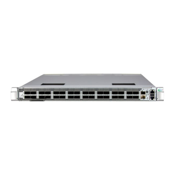
Chapter 4: Ports and Indicators Chapter 4 Ports and Indicators This chapter covers the ports and LED indicators found on the SSE-T7132 series switch. 4.1 Front View Figure 4-1. Front View Front Features Item Description 32 QSFP-DD 400G ports Two SFP+10G ports... -
Page 32: Rear View
Chapter 4: Ports and Indicators 4.2 Rear View Figure 4-2. Rear View Rear Features Item Description Six hot-swappable FAN module Two hot-swappable power supplies... -
Page 33: Ports
Chapter 4: Ports and Indicators 4.3 Ports The SSE-T7132 series switches all include the front ports listed below. QSFP-DD Ports 32 QSFP-DD ports for 400G, 200G, 100G, 50G, 40G, 25G, and 10G connections. Note 1: Support up to 12W per port. -
Page 34: Qsfp-Dd Ports Led
Chapter 4: Ports and Indicators QSFP-DD Ports LED LED Locations LED1 LED2 LED3 LED4 LED1 LED2 LED3 LED4 Single Port Cable Port Mode Location The Behavior of Each LED LED1 LED1 to LED4 shows the 400G port status: LED2 All Off: Link down 400G BASE-R8 All Solid Green: Link up LED3... -
Page 35: Split Cable: One Port To Two Ports
Chapter 4: Ports and Indicators Split Cable: One Port to Two Ports Port Mode Location The Behavior of each LED LED1 and LED2 shows the 200G port-A status: LED1 All Off: Link down All Solid Green: Link up LED2 All Blinking Green: Transmitting / Receiving data 200G BASE-R4 LED3 and LED4 shows the 200G port-B status: LED3... -
Page 36: Split Cable: One Port To Eight Ports
Chapter 4: Ports and Indicators Split Cable: One Port to Eight Ports Port Mode Location The Behavior of each LED LED1 shows the 50G port-A and port-B status: Off: Two ports link down LED1 Single Solid green: Two ports link up Single Solid orange: One port link up and one port link down Blinking: Transmitting / Receiving data LED2 shows the 50G port-C and port-D status:... -
Page 37: Sfp+ Ports Led
Chapter 4: Ports and Indicators Port Mode Location The Behavior of each LED LED1 shows the 10G port-A and port-B status: Off: Two ports link down LED1 Single Solid green: Two ports link up Single Solid orange: One port link up and one port link down Blinking: Transmitting / Receiving data LED2 shows the 10G port-C and port-D status: Off: Two ports link down... -
Page 38: Qsfp-Dd/Sfp Cable/Transceiver/Module
Chapter 4: Ports and Indicators 4.5 QSFP-DD/SFP Cable/Transceiver/Module Cable Type Cable Model Length SMC P/N QSFP-DD 400g TO 400g 10M AOC CBL-QSFPDD-400G-AOC-10 Transceivers QSFP-DD 400G-SR8 100Meter up to 100m TRX-400G-SR8-01 Warnings Warning 1: Laser Class 1 optical transceiver shall be used only. Warning 2: This end product is for use with field installable LDMs not provided with the product when shipped from the original equipment manufacturer. -
Page 39: Appendix A Rack Installation
Rack Installation A.1 Overview Some Supermicro switches can be equipped with an optional rail kit to make it easy to install them in a rack. This manual provides instructions for installing the mounting rails onto a rack and for installing the switch into the mounting rails. Following these steps in the order given should enable you to have the system operational within a minimum amount of time. - Page 40 Appendix A: Rack Installation A.4 Warnings and Precautions! Rack Precautions • Ensure that the leveling jacks on the bottom of the rack are fully extended to the floor with the full weight of the rack resting on them. • In a single rack installation, stabilizers should be attached to the rack. •...
- Page 41 SSE-T7132 Series User's Manual Lithium Battery Precaution • This switch may contain a lithium battery. There is a danger of explosion if the battery is incorrectly replaced. • Installing the battery upside-down may reverse the polarities and cause the battery to explode.
- Page 42 Appendix A: Rack Installation Reliable Ground A reliable ground (earth) must be maintained at all times. To ensure this, the rack itself should be grounded. Particular attention should be given to power supply connections other than the direct connections to the branch circuit (i.e. the use of power strips, etc.). A.5 Rack Mounting Instructions This chapter provides information on installing the switch into a rack unit with the rail kit.
- Page 43 SSE-T7132 Series User's Manual Identifying the Sections of the Rack Rails The rail kit package includes two rack rail assemblies in the rack mounting kit. Each assembly consists of three sections: An inner rail that secures directly to the chassis, an outer rail that secures to the rack, and a middle rail which extends from the outer rail.
- Page 44 Appendix A: Rack Installation Separating the Sections of the Rails The rail kit ships with the front inner rail attached to the front outer rail. These must be separated prior to installation in the rack. Use the procedure below to separate the rails. Releasing the Inner Rail Each inner rail has a locking latch.
- Page 45 SSE-T7132 Series User's Manual Removing/Installing the Inner Rails Use the procedure below and Figure A-2 to remove/install the inner rails. Installing the Inner Rails on the Switch 1. Identify the left and right inner rails. They are labeled. 2. Place the inner rail firmly against the side of the chassis, aligning the holes on the inner rail with the T-studs on the front side of the chassis.
- Page 46 Appendix A: Rack Installation Installing the Outer Rails onto the Rack Follow the steps below to assemble and install the outer rails on the rack. Installing the Outer Rails on the Rack 1. Align the outer rail and the standard square on the guide pin. The guide pin on the brackets is for E1A standard square hole 9.5mm x 9.5mm (1U).
- Page 47 SSE-T7132 Series User's Manual 4. Pull the lever forward to release the latch, and push the middle rail to the rear of the rail. Rear Front Push the middle rail. 5. Turn the latch to the open position and push the pegs into the front rack holes.
- Page 48 Appendix A: Rack Installation Installing the Switch into a Rack Use the procedure and Figure A-3 below to install the switch into a rack. Warning: Mounting the system into the rack requires at least two people to support the chassis during installation.
Need help?
Do you have a question about the SSE-T7132 Series and is the answer not in the manual?
Questions and answers