
Related Manuals for Supermicro SSE-G3648B


Summary of Contents for Supermicro SSE-G3648B
- Page 1 SSE-G3648B/BR Switch Installation Guide SSE-G3648B SSE-G3648BR Switch Installation Guide Revision 1.0 Page 1...
- Page 2 Super Micro Computer, Inc. (“Supermicro”) reserves the right to make changes to the product described in this manual at any time and without notice. This product, including software, if any, and documentation may not, in whole or in part, be copied, photocopied, reproduced, translated or reduced to any medium or machine without prior written consent.
-
Page 3: Table Of Contents
SSE-G3648B/BR Switch Installation Guide Contents Introduction .....................5 Overview ......................5 Description of Hardware ..................6 Front Panel......................... 6 Back Panel ......................... 6 Status LEDs ......................7 Port Description ....................8 Power Supply Module ..................10 Fan Module ......................11 System Specifications..................11 Standardized Warning Statements ............ - Page 4 SSE-G3648B/BR Switch Installation Guide Installing the Switch ....................33 Installing the main Power Supply Module ............34 Installing the Second Power Supply Module ............34 Installing the Fan ..................... 36 Connecting the Console ..................37 SFP/SFP+ Transceiver Installation ................ 38 Copper Cable/Fiber Cable Connection ..............
-
Page 5: Introduction
Introduction Overview The Supermicro SSE-G3648B and SSE-G3648BR are a new generation of 1/10G Ethernet aggregation switches. They offer 1G Ethernet connectivity for servers and end users as well as access to 10G backbone networks and/or servers with higher speed connectivity. The available redundant power supply option is but one of the many features making them attractive for use in the modern data center. -
Page 6: Description Of Hardware
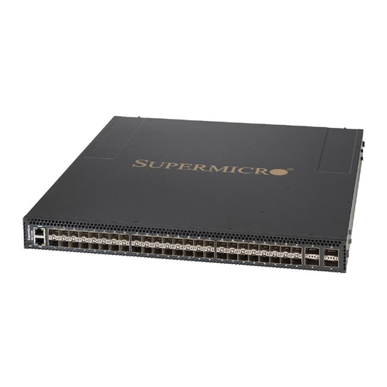
SSE-G3648B/BR Switch Installation Guide Description of Hardware Front Panel Front Panel Diagram The front panel descriptions of the SSE-G3648B/BR switches are given in the following table: Table 1-1: Front Panel Descriptions of SSE-G3648B/BR Switches 10/100/1000Base-T RJ45 Console USB 2.0 Type... -
Page 7: Status Leds
(with Second Power Supply Installed) Status LEDs The indicator light on front panel of the SSE-G3648B/BR has forty-eight RJ45 port indicator lights, four SFP+ port indicator lights, two power supply indicator lights and a system automatic diagnostics LED. They are shown below and described in the following table. -
Page 8: Port Description
Blinking Amber The 10M/100M port transmitting data No light No connection or fail to connect Port Description The SSE-G3648B/BR provide forty-eight RJ45 ports and four 10 Gb SFP+ ports. SSE-G3648B/BR series switches support the following SFP transceivers: • SFP-SX-L transceiver •... - Page 9 9/125um single mode fiber: 70km SFP-LH-120-L transceiver 9/125um single mode fiber: 120km SSE-G3648B/BR switches provide 4 SFP+ ports. In addition to support of optical fiber connections through transceivers, they support SFP+ Direct Attach Copper (DAC) cables (0.5M-7M). This provides enhanced flexibility in network design and installation.
-
Page 10: Power Supply Module
The following picture is the power supply module (PSM) of SSE-G3648B/BR.: Fig 1-5: SSE-G3648B/BR PSM SSE-G3648B/BR switches have one PSM in the standard configuration. When two power supplies are installed, they give power redundancy. The maximum input power is 200W @ 90VAC~264VAC/47HZ~63HZ. Output is 12V +/- 5%. -
Page 11: Fan Module
Fan Module The SSE-G3648B/BR series fan module is shown below: Fig 1-6: Fan Module SSE-G3648B/BR switches have three fan modules. The rotation speed of the fan is self- adjusting, based upon system temperature, and supports hot plug. System Specifications Table 1-5: System Specifications of SSE-G3648B/BR Switches... -
Page 12: Standardized Warning Statements
The following statements are industry standard warnings, provided to warn the user of situations which have the potential for bodily injury. Should you have questions or experience difficulty, contact Supermicro's Technical Support department for assistance. Only certified technicians should attempt to install or configure components. - Page 13 SSE-G3648B/BR Switch Installation Guide 此警告符号代表危险。 您正处于可能受到严重伤害的工作环境中。在您使用设备开始工作之前,必须充分意识到触电 的危险,并熟练掌握防止事故发生的标准工作程序。请根据每项警告结尾的声明号码找到此设 备的安全性警告说明的翻译文本。 此警告符號代表危險。 您正處於可能身體可能會受損傷的工作環境中。在您使用任何設備之前,請注意觸電的危險, 並且要熟悉預防事故發生的標準工作程序。請依照每一注意事項後的號碼找到相關的翻譯說明 內容。 Warnung WICHTIGE SICHERHEITSHINWEISE Dieses Warnsymbol bedeutet Gefahr. Sie befinden sich in einer Situation, die zu Verletzungen führen kann. Machen Sie sich vor der Arbeit mit Geräten mit den Gefahren elektrischer Schaltungen und den üblichen Verfahren zur Vorbeugung vor Unfällen vertraut.
- Page 14 SSE-G3648B/BR Switch Installation Guide 안전을 위한 주의사항 경고! 이 경고 기호는 위험이 있음을 알려 줍니다. 작업자의 신체에 부상을 야기 할 수 있는 상태에 있게 됩니다. 모든 장비에 대한 작업을 수행하기 전에 전기회로와 관련된 위험요소들을 확인하시고 사전에 사고를 방지할 수 있도록 표준 작업절차를 준수해 주시기 바랍니다.
-
Page 15: Installation Instructions
SSE-G3648B/BR Switch Installation Guide BELANGRIJKE VEILIGHEIDSINSTRUCTIES Dit waarschuwings symbool betekent gevaar. U verkeert in een situatie die lichamelijk letsel kan veroorzaken. Voordat u aan enige apparatuur gaat werken, dient u zich bewust te zijn van de bij een elektrische installatie betrokken risico's en dient u op de hoogte te zijn van de standaard procedures om ongelukken te voorkomen. -
Page 16: Circuit Breaker
SSE-G3648B/BR Switch Installation Guide Waarschuwing Raadpleeg de installatie-instructies voordat u het systeem op de voedingsbron aansluit. Circuit Breaker Warning! This product relies on the building's installation for short-circuit (overcurrent) protection. Ensure that the protective device is rated not greater than: 250 V, 20 A サーキット・ブレーカー... -
Page 17: Power Disconnection Warning
SSE-G3648B/BR Switch Installation Guide Attention Pour ce qui est de la protection contre les courts-circuits (surtension), ce produit dépend de l'installation électrique du local. Vérifiez que le courant nominal du dispositif de protection n'est pas supérieur à :250 V, 20 A. - Page 18 SSE-G3648B/BR Switch Installation Guide 在您打開機殼安裝或移除內部元件前,必須將系統完全斷電,並移除電源線。 Warnung Das System muss von allen Quellen der Energie und vom Netzanschlusskabel getrennt sein, das von den Spg.Versorgungsteilmodulen entfernt wird, bevor es auf den Chassisinnenraum zurückgreift, um Systemsbestandteile anzubringen oder zu entfernen. ¡Advertencia! El sistema debe ser disconnected de todas las fuentes de energía y del cable eléctrico quitado de los módulos de fuente de alimentación antes de tener acceso el interior del chasis...
-
Page 19: Equipment Installation
SSE-G3648B/BR Switch Installation Guide Equipment Installation Warning! Only trained and qualified personnel should be allowed to install, replace, or service this equipment. 機器の設置 トレーニングを受け認定された人だけがこの装置の設置、交換、またはサービスを許可され ています。 警告 只有经过培训且具有资格的人员才能进行此设备的安装、更换和维修。 警告 只有經過受訓且具資格人員才可安裝、更換與維修此設備。 Warnung Das Installieren, Ersetzen oder Bedienen dieser Ausrüstung sollte nur geschultem, qualifiziertem Personal gestattet werden. -
Page 20: Restricted Area
SSE-G3648B/BR Switch Installation Guide Restricted Area Warning! This unit is intended for installation in restricted access areas. A restricted access area can be accessed only through the use of a special tool, lock and key, or other means of security. -
Page 21: Battery Handling
SSE-G3648B/BR Switch Installation Guide 이 장치는 접근이 제한된 구역에 설치하도록 되어있습니다. 특수도구, 잠금 장치 및 키, 또는 기타 보안 수단을 통해서만 접근 제한 구역에 들어갈 수 있습니다. Waarschuwing Dit apparaat is bedoeld voor installatie in gebieden met een beperkte toegang. Toegang tot dergelijke gebieden kunnen alleen verkregen worden door gebruik te maken van speciaal gereedschap, slot en sleutel of andere veiligheidsmaatregelen. -
Page 22: Comply With Local And National Electrical Codes
SSE-G3648B/BR Switch Installation Guide Attention Danger d'explosion si la pile n'est pas remplacée correctement. Ne la remplacer que par une pile de type semblable ou équivalent, recommandée par le fabricant. Jeter les piles usagées conformément aux instructions du fabricant. ¡Advertencia! Existe peligro de explosión si la batería se reemplaza de manera incorrecta. -
Page 23: Product Disposal
SSE-G3648B/BR Switch Installation Guide ¡Advertencia! La instalacion del equipo debe cumplir con las normas de electricidad locales y nacionales. Attention L'équipement doit être installé conformément aux normes électriques nationales et locales. 경고! 현 지역 및 국가의 전기 규정에 따라 장비를 설치해야 합니다. -
Page 24: Power Cable And Ac Adapter
SSE-G3648B/BR Switch Installation Guide Al deshacerse por completo de este producto debe seguir todas las leyes y reglamentos nacionales. Attention La mise au rebut ou le recyclage de ce produit sont généralement soumis à des lois et/ou directives de respect de l'environnement. Renseignez-vous auprès de l'organisme compétent. - Page 25 Brand entstehen. Elektrische Geräte und Material Safety Law verbietet die Verwendung von UL-oder CSA-zertifizierte Kabel, UL oder CSA auf der Code für alle anderen elektrischen Geräte als Produkte von Supermicro nur bezeichnet gezeigt haben. ¡Advertencia! Al instalar el producto, utilice los cables de conexión previstos o designados, los cables y adaptadores de CA.
- Page 26 Het gebruik van andere kabels en adapters kan leiden tot een storing of een brand. Elektrisch apparaat en veiligheidsinformatiebladen wet verbiedt het gebruik van UL of CSA gecertificeerde kabels die UL of CSA die op de code voor andere elektrische apparaten dan de producten die door Supermicro alleen. Page 26...
-
Page 27: Installation Requirements
Dust and Particles Dust is harmful to the safe operation of SSE-G3648B/BR switches. Dust can lead to electrostatic adherence, especially likely under low relative humidity, causing poor contact of metal connectors or contacts. Electrostatic adherence will result in not only reduced product lifespan, but also increased chance of communication failures. -
Page 28: Temperature And Humidity
E1031 Series switch Installation Guide Chapter 2 Installation Notice Table 3-2: Environmental Requirements: Particles Average (mg/m³) Max (mg/m³) 0.006 0.03 0.04 0.15 0.05 0.15 0.01 Temperature and Humidity Although the switch is designed to use 3 fans, the site should still maintain a desirable temperature and humidity. -
Page 29: Power Supply
E1031 Series switch Installation Guide Chapter 2 Installation Notice Power Supply Before powering on the power supply, please check the power input to ensure proper grounding of the power supply system. The input source for the switch should be reliable and secure; a voltage adaptor can be used if necessary. -
Page 30: Installation Notice
E1031 Series switch Installation Guide Chapter 2 Installation Notice The SSE-G3648B/BR switches are designed to be mounted on a standard 19’’ rack - please ensure good ventilation for the rack. • Every device in the rack will generate heat during operation, therefore vent and fans must be provided for an enclosed rack, and devices should not be stacked closely. -
Page 31: Security Warnings
E1031 Series switch Installation Guide Chapter 2 Installation Notice Security Warnings Read and follow these security warnings: • When using an SFP/SFP+ transceiver, do not stare directly at the fiber bore when the switch is in operation. Otherwise the laser may severely damage your eyes. •... -
Page 32: Device Installation
Chapter 3 Device Installation 4. Device Installation Installation Preparation In order to prepare for installation of the SSE-G3648B/BR switch, you must verify the package contents and use the required tools and utilities. Verify the Package Contents Please unpack the shipping package and verify carefully the contents inside. -
Page 33: Device Installation
Figure 4-1 SSE-G3648B/BR Switch Installed In A Rack Please mount the SSE-G3648B/BR in the 19’’ rack as follows: 1. Attach the 2 brackets on the SSE-G3648B/BR with screws provided in the accessory kit. 2. Provide additional support (e.g., rack shelf) for the switch when installing because the machine is fairly heavy. -
Page 34: Installing The Main Power Supply Module
E1031Series switch Installation Guide Chapter 3 Device Installation Installing the Main Power Supply Module SSE-G3648B/BR switches support 2 power supplies (One power supply is provided in the standard configuration). Figure 4-2a: SSE-G3648B/BR Switch Power Supply Installation – Single Power Supply Please follow these instructions for installing and removing the main power supply module: 1. - Page 35 E1031Series switch Installation Guide Chapter 3 Device Installation Figure 4-2b SSE-G3648B/BR Switch Power Supply Installation – Second (Redundant Back-Up) Power Supply Please follow these instructions for installing and removing the second power supply module: 1. Remove the blanking plate (two screws) which covers the opening of the slot for the second power supply.
-
Page 36: Installing The Fan
E1031Series switch Installation Guide Chapter 3 Device Installation Installing the Fan The SSE-G3648B/BR switch has three fans in its standard configuration. Figure 4-3: SSE-G3648B/BR Switch Fan Installation Please install or remove the fan module as follows: The golden fingers should be positioned inward and on the back of the switch. After proper insertion you can hear the lock sound of “click”. -
Page 37: Connecting The Console
Connecting the Console SSE-G3648B/BR switches include a serial console port. Figure 4-4: Connecting a Console to the SSE-G3648B/BR Switches The connection procedure is listed below: 1. Find the console cable provided in the accessory kit. Attach the console cable end to the console port of the switch. -
Page 38: Sfp/Sfp+ Transceiver Installation
E1031Series switch Installation Guide Chapter 3 Device Installation SFP/SFP+ Transceiver Installation SSE-G3648B/BR switches provide forty-eight RJ45 connector slots and four SFP+ ports. The procedure for installing an SFP+ transceiver is shown below: 1. Put on a ESD wrist strap (or antistatic gloves) 2. - Page 39 Figure 4-5: Connect the DAC Cable to SSE-G3648B/BR Switch The connection approach of DAC cable is below: Connect the end of the DAC cable into the SFP+ port of the SSE-G3648B/BR switch. Check the indicator light state of the light port. If the LINK light is bright, it means the link is connected.
-
Page 40: Ac Power Supply Connection
E1031Series switch Installation Guide Chapter 3 Device Installation AC Power Supply Connection SSE-G3648B/BR series switches use 220/110VAC power supply by default. Please read the power input specification for detailed information. Figure 4-6: Connecting the Power Supply Cable to the SSE-G3648B/BR Switch The AC Power supply connection procedure is described as below: 1. -
Page 41: Checking The Switch
E1031Series switch Installation Guide Chapter 3 Device Installation Checking the Switch • Does the power used correspond to the power on the label? • Is the ground cable is connected? • Is the Console cable connected to power cable correctly? •...
Need help?
Do you have a question about the SSE-G3648B and is the answer not in the manual?
Questions and answers