Table of Contents
Advertisement
Quick Links
Advertisement
Table of Contents

Related Manuals for Supermicro SSE-X3648S


Summary of Contents for Supermicro SSE-X3648S
- Page 1 SSE-X3648S Switch SSE-X3648SR Switch Installation Manual Revison 1.0...
- Page 2 This product, including software and documentation, is the property of Supermicro and/or its licensors, and is supplied only under a license. Any use or reproduction of this product is not allowed, except as expressly permitted by the terms of said license.
-
Page 3: About This Manual
LANs (Local Area Networks). It provides information for the installation and use of the Supermicro's SSE-X3648S and SSE-X3648SR switches. Installation and maintenance should be performed by experienced professionals only. - Page 4 SSE-X3648S Switch User’s Guide Notes...
-
Page 5: Table Of Contents
Table of Contents Table of Contents Chapter 1 Introduction ............... 1-1 1-1 Features and Benefits ..............1-1 1-2 Description of Hardware ..............1-1 Front Panel ..................... 1-1 Back Panel....................1-2 1-3 Status LEDs ..................1-2 1-4 Port Description ................. 1-4 1-5 Power Supply Module ............... - Page 6 SSE-X3648S/SSE-X3648SR Switch Installation Manual Chapter 4 Device Installation ............4-1 4-1 Installation Preparation ..............4-1 Verify the Package Contents..............4-1 Required Tools and Utilities ..............4-1 4-2 Device Installation ................4-2 Installing the Switch in a Shelf Rack ............4-2 Installing the Switch into a Rail Rack ............
-
Page 7: Chapter 1 Introduction
Chapter 1: Introduction Chapter 1 Introduction The SSE-X3648S and SSE-X3648SR switches are the latest generation of 10Gb Ethernet routing switches from Supermicro. They are based on 10Gb switching technology and are designed for aggregating connectivity to 40Gb servers in data centers –... -
Page 8: Back Panel
QSFP+ Ports Back Panel The SSE-X3648S/SSE-X3648SR switches provides an RJ-45 serial console port in the rear of the switch. Users perform the local and telnet configuration through this port. The back panel of the SSE-X3648S/SSE-X3648SR switch also includes two redundant hot-swappable AC power supply modules, four fans and one rear panel card. - Page 9 Chapter 1: Introduction Table 1-3. Front Panel Status LEDs Indicator Front Panel State Description Light Sign Green light always on Power supply module operating normally. Power Supply P-1/P-2 Indicator Light No Light No power supply or error. The system is powered on and running Green light always on normally.
-
Page 10: Port Description
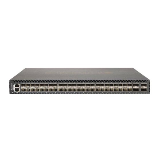
SSE-X3648S/SSE-X3648SR Switch Installation Manual Port Description The SSE-X3648S/SSE-X3648SR provides 48 10Gb SFP+ ports and 6 40Gb QSFP+ ports. The following SFP transceivers are supported: • SFP-SX-L transceiver • SFP-LX-L transceiver • SFP-LX-20-L 20-km transceiver • SFP-LX-40 40-km mid distance transceiver •... -
Page 11: Power Supply Module
Figure 1-3. 460W Power Supply Module The SSE-X3648S/SSE-X3648SR switch has two power supply modules, thus providing redundancy. It provides airflow front to back (SSE-X3648S) or airflow back to front (SSE-X3648SR). The maximum power is 460W, while the input is 100VAC~240VAC, and the output is 12V +/- 5%. -
Page 12: Fan Module
Figure 1-4. Fan Module The SSE-X3648S/SSE-X3648SR switch has four fan modules in its standard configuration. The rotation speed of the fan self-adjusts to adapt to system temperature, and provides airflow front to back (SSE-X3648S) and airflow back to front (SSE-X3648SR). Cautions: 1. -
Page 13: System Specifications
Chapter 1: Introduction System Specifications System specifications are shown in Table 1-8 below. Table 1-8. System Specifications Specification Description Dimensions(W * H * D) (mm) 433.8 * 44 * 550 Weight 10.133 kg Fixed Port 48 SFP+ ports; 6 QSFP+ ports Management Port 1 RJ-45 serial console port Power Input... - Page 14 SSE-X3648S/SSE-X3648SR Switch Installation Manual Notes...
-
Page 15: Chapter 2 Standardized Warning Statements
The following statements are industry standard warnings, provided to warn the user of situations which have the potential for bodily injury. Should you have questions or experience difficulty, contact Supermicro's Technical Support department for assistance. Only certified technicians should attempt to install or configure components. - Page 16 SSE-X3648S/SSE-X3648SR Switch Installation Manual Warnung WICHTIGE SICHERHEITSHINWEISE Dieses Warnsymbol bedeutet Gefahr. Sie befinden sich in einer Situation, die zu Verletzungen führen kann. Machen Sie sich vor der Arbeit mit Geräten mit den Gefahren elektrischer Schaltungen und den üblichen Verfahren zur Vorbeugung vor Unfällen vertraut.
-
Page 17: Installation Instructions
Chapter 2: Standardized Warning Statements 이 경고 기호는 위험이 있음을 알려 줍니다 . 작업자의 신체에 부상을 야기 할 수 있는 상태에 있게 됩니다 . 모든 장비에 대한 작업을 수행하기 전에 전기회로와 관련된 위험 요소들을 확인하시고 사전에 사고를 방지할 수 있도록 표준 작업절차를 준수해 주시기 바랍니다... -
Page 18: Circuit Breaker
SSE-X3648S/SSE-X3648SR Switch Installation Manual ﻣﺼﺪر ﻟﻠﻄﺎﻗﺔ اﻟﻨﻈﺎم إﻟﻰ ﻗﺒﻞ ﺗﻮﺻﯿﻞ ﺘﺮﻛﯿﺐ اﻗﺮ إرﺷﺎدات اﻟ 시스템을 전원에 연결하기 전에 설치 안내를 읽어주십시오 . Waarschuwing Raadpleeg de installatie-instructies voordat u het systeem op de voedingsbron aansluit. Circuit Breaker Warning! This product relies on the building's installation for short-circuit (overcurrent) protection. -
Page 19: Power Disconnection Warning
Chapter 2: Standardized Warning Statements ﻓﻲ اﻟﺘﻲ ﺗﻢ ﺗﺜﺒﯿﺘﮭﺎ ﻣﻦ اﻟﺪواﺋﺮاﻟﻘﺼﯿﺮة اﻟﺤﻤﺎﯾﺔ ﻣﻌﺪات ﯾﻌﺘﻤﺪ ﻋﻠﻰ ھﺬا اﻟﻤﻨﺘﺞ اﻟﻤﺒﻨﻰ أﻛﺜﺮ ﻣﻦ ﻟﯿﺲ ﻮﻗﺎﺋﻲ اﻟ اﻟﺠﮭﺎز ﺗﻘﯿﯿﻢ أن ﺗﺄﻛﺪ ﻣﻦ 20A, 250V 경고 ! 이 제품은 전원의 단락 ( 과전류 ) 방지에 대해서 전적으로 건물의 관련 설비에 의존합니 다... -
Page 20: Equipment Installation
SSE-X3648S/SSE-X3648SR Switch Installation Manual ¡Advertencia! El sistema debe ser disconnected de todas las fuentes de energía y del cable eléctrico quitado de los módulos de fuente de alimentación antes de tener acceso el interior del chasis para instalar o para quitar componentes de sistema. -
Page 21: Restricted Area
Chapter 2: Standardized Warning Statements Warnung Das Installieren, Ersetzen oder Bedienen dieser Ausrüstung sollte nur geschultem, qualifiziertem Personal gestattet werden. ¡Advertencia! Solamente el personal calificado debe instalar, reemplazar o utilizar este equipo. Attention Il est vivement recommandé de confier l'installation, le remplacement et la maintenance de ces équipements à... - Page 22 SSE-X3648S/SSE-X3648SR Switch Installation Manual Warnung Diese Einheit ist zur Installation in Bereichen mit beschränktem Zutritt vorgesehen. Der Zutritt zu derartigen Bereichen ist nur mit einem Spezialwerkzeug, Schloss und Schlüssel oder einer sonstigen Sicherheitsvorkehrung möglich. ¡Advertencia! Esta unidad ha sido diseñada para instalación en áreas de acceso restringido. Sólo puede obtenerse acceso a una de estas áreas mediante la utilización de una...
-
Page 23: Battery Handling
Chapter 2: Standardized Warning Statements Battery Handling Warning! There is the danger of explosion if the battery is replaced incorrectly. Replace the battery only with the same or equivalent type recommended by the manufacturer. Dispose of used batteries according to the manufacturer's instructions. 電池の取り扱い... -
Page 24: Comply With Local And National Electrical Codes
SSE-X3648S/SSE-X3648SR Switch Installation Manual 배터리가 올바르게 교체되지 않으면 폭발의 위험이 있습니다 . 기존 배터리와 동일하거 나 제조사에서 권장하는 동등한 종류의 배터리로만 교체해야 합니다 . 제조사의 안내에 따라 사용된 배터리를 처리하여 주십시오 . Waarschuwing Er is ontploffingsgevaar indien de batterij verkeerd vervangen wordt. Vervang de batterij slechts met hetzelfde of een equivalent type die door de fabrikant aanbevolen wordt. -
Page 25: Product Disposal
Chapter 2: Standardized Warning Statements 경고 ! 현 지역 및 국가의 전기 규정에 따라 장비를 설치해야 합니다 . Waarschuwing Bij installatie van de apparatuur moet worden voldaan aan de lokale en nationale elektriciteitsvoorschriften. Product Disposal Warning! Ultimate disposal of this product should be handled according to all national laws and regulations. -
Page 26: Power Cable And Ac Adapter
Fehlfunktion oder ein Brand entstehen. Elektrische Geräte und Material Safety Law verbietet die Verwendung von UL-oder CSA-zertifizierte Kabel, UL oder CSA auf der Code für alle anderen elektrischen Geräte als Produkte von Supermicro nur bezeichnet gezeigt haben. - Page 27 Appareils électroménagers et de loi sur la sécurité Matériel interdit l'utilisation de UL ou CSA câbles certifiés qui ont UL ou CSA indiqué sur le code pour tous les autres appareils électriques que les produits désignés par Supermicro seulement. י מ...
- Page 28 Het gebruik van andere kabels en adapters kan leiden tot een storing of een brand. Elektrisch apparaat en veiligheidsinformatiebladen wet verbiedt het gebruik van UL of CSA gecertificeerde kabels die UL of CSA die op de code voor andere elektrische apparaten dan de producten die door Supermicro alleen. 2-14...
-
Page 29: Chapter 3 Installation Requirements
Dust and Particles Dust is harmful to the safe operation of the SSE-X3648S/SSE-X3648SR switch. Dust can lead to electrostatic discharge, especially likely under low relative humidity, causing poor contact of metal connectors or contacts. Electrostatic discharge will result in not only reduced product lifespan, but also increased chance of communication failures. -
Page 30: Temperature And Humidity
SSE-X3648S/SSE-X3648SR Switch Installation Manual Table 3-2. Environmental Requirements: Particles Average (mg/m³) Max (mg/m³) 0.006 0.03 0.04 0.15 0.05 0.15 0.01 Temperature and Humidity Although the switch is designed to use 4 fans, the site should still maintain a desirable temperature and humidity. High-humidity conditions can cause electrical resistance degradation or even electric leakage, degradation of mechanical properties and corrosion of internal components. -
Page 31: Power Supply
Chapter 3: Installation Requirements Power Supply Before powering on the power supply, please check the power input to ensure proper grounding of the power supply system. The input source for the switch should be reliable and secure; a voltage adaptor can be used if necessary. The building’s circuit protection system should include in the circuit a fuse or circuit-breaker of no greater than 240 V, 5A. -
Page 32: Rack Configuration
Be sure to check the positioning of the switch after installation to avoid the aforementioned. Caution! If a standard nineteen inch rack is not available, the SSE-X3648S/SSE-X3648SR switches can be placed on a clean level desktop; leave a clearance of 100mm around the switch for ventilation, and do not place anything on top of the switch. -
Page 33: Security Warnings
Chapter 3: Installation Requirements Security Warnings Read and follow the following security warnings: • When using a SFP/SFP+/QSFP+ transceiver, do not stare directly at the fiber bore when the switch is in operation. Otherwise the laser may hurt your eyes. •... - Page 34 SSE-X3648S/SSE-X3648SR Switch Installation Manual Notes...
-
Page 35: Chapter 4 Device Installation
Chapter 4 Device Installation Installation Preparation In order to prepare for installation of the SSE-X3648S/SSE-X3648SR switch, you must verify the package contents and use the required tools and utilities. Verify the Package Contents Please unpack the shipping package and verify carefully the contents inside.: •... -
Page 36: Device Installation
To install the SSE-X3648S/SSE-X3648SR switch use the following sections. Installing the Switch in a Shelf Rack Figure 4-1. The SSE-X3648S/SSE-X3648SR Switches Installed in a Shelf Rack Please mount the SSE-X3648S/SSE-X3648SR switches on the nineteen inch shelf rack as follows: Installing the SSE-X3648S/SSE-X3648SR Switches into a Shelf Rack 1. -
Page 37: Installing The Switch Into A Rail Rack
Installing the Switch into a Rail Rack Figure 4-2. SSE-X3648S/SSE-X3648SR Switches Installed in a Rail Rack Alternately the SSE-X3648S/SSE-X3648SR switches can be installed in a rail rack with the rails provided. For this type of installation, do the following: Installing the SSE-X3648S/SSE-X3648SR Switches into a Rail Rack 1. -
Page 38: Installing The Power Supply Module
SSE-X3648S/SSE-X3648SR Switch Installation Manual Installing the Power Supply Module The SSE-X3648S/SSE-X3648SR switches support two power supplies. Please install the power supply module according to the following procedure. Installing the Power Supply Module 1. The golden finger of the power supply should be inserted end downwards. Once secure, you can hear the lock sound “click”. -
Page 39: Installing The Fan
Chapter 4: Device Installation Installing the Fan The SSE-X3648S/SSE-X3648SR switches have four fans in a standard configuration. Figure 4-4. Installing a Fan in the Switch Please install the fan module according to the following approach: Installing a Fan into the Switch 1. -
Page 40: Connecting The Console
SSE-X3648S/SSE-X3648SR Switch Installation Manual Connecting the Console The SSE-X3648S/SSE-X3648SR switches provide a serial console port on the rear of the switch. The connection procedure for this port is listed below: Connecting the Console to the Switch 1. Find the console cable provided in the accessory kit. Attach the console cable end to console port in the rear of the switch. -
Page 41: Copper Cable/Fiber Cable Connection
Chapter 4: Device Installation Copper Cable/Fiber Cable Connection Copper cables should be connected as described below. Connecting Copper Cables 1. Insert one end of the Ethernet cable to the RJ-45 Ethernet port in the switch copper port; 2. Insert the other end of the Ethernet cable to the RJ-45 Ethernet port of other device; 3. - Page 42 SSE-X3648S/SSE-X3648SR Switch Installation Manual Figure 4-6. Connecting a DAC Cable to the Switch Connecting the DAC cable is described below. Connecting the DAC Cable 1. Connect the two sides of the DAC cable to the SFP/SFP+/QSFP+ port of the SSE-X3648S/SSE-X3648SR switches.
-
Page 43: Ac Power Supply Connection
2. Check the power status indicator in the front panel of the switch. The corresponding PWR indicator should light. The SSE-X3648S is self-adjusting for the input voltage. As soon as the input voltage is in the range printed on the switch surface, the switch can operate correctly. -
Page 44: Grounding Cable Connection
SSE-X3648S/SSE-X3648SR Switch Installation Manual Grounding Cable Connection Figure 4-8. Connect the Grounding Cable to the Switch Please connect the grounding cable according to the following procedure. Connecting the Grounding Cable 1. Cover one side of the grounding cable to the earthing pillar of the back panel. - Page 45 Disclaimer The products sold by Supermicro are not intended for and will not be used in life support systems, medical equipment, nuclear facilities or systems, aircraft, aircraft devices, aircraft/emergency communication devices or other critical systems whose failure to perform be reasonably expected to result in significant injury or loss of life or catastrophic property damage.
- Page 46 SSE-X3648S/SSE-X3648SR Switch Installation Manual...
Need help?
Do you have a question about the SSE-X3648S and is the answer not in the manual?
Questions and answers