Supermicro SSE-G24-TG4 User Manual
Layer 2/3 1/10 gigabit ethernet switches
Hide thumbs
Also See for SSE-G24-TG4:
- User manual (318 pages) ,
- Configuration manual (34 pages) ,
- Stacking manual (16 pages)

Related Manuals for Supermicro SSE-G24-TG4


Summary of Contents for Supermicro SSE-G24-TG4
- Page 1 Layer 2/3 1/10 Gigabit Ethernet Switches SSE-G24-TG4 1/10 Gigabit Ethernet Switch SSE-G48-TG4 1/10 Gigabit Ethernet Switch User’s Manual Revison 1.0a...
- Page 2 Please Note: For the most up-to-date version of this manual, please see our web site at www.supermicro.com. Super Micro Computer, Inc. (“Supermicro”) reserves the right to make changes to the product described in this manual at any time and without notice. This product, including software, if any, and documentation may not, in whole or in part, be copied, photocopied, reproduced, translated or reduced to any medium or machine without prior written consent.
-
Page 3: Table Of Contents
Command Line..................3-2 Firmware ....................3-3 Firmware Upgrading Procedures ............3-3 Firmware Failure Recovery Steps ............3-6 Chapter 4 Ports and Indicators ............ 4-1 4-1 SSE-G24-TG4 Ports and Indicators ..........4-1 4-2 SSE-G48-TG4 Ports and Indicators ..........4-2 4-3 Ports ....................4-3 RJ-45 Compatible Port................ - Page 4 Layer 2/3 1/10 Gigabit Ethernet Switches User’s Manual 5-3 Home Page ..................5-4 Top Page Links ..................5-6 Top LED Display ..................5-6 Left Side Tree..................5-7 Middle Configuration Link Table.............. 5-7 5-4 System Management Page ............. 5-8 System Settings ..................5-8 System Settings ...................
- Page 5 Table of Contents SNMP AgentX ..................5-39 RMON ....................5-40 RMON Basic Settings ................ 5-40 Event Configuration................5-41 RMON Alarm Configuration ............... 5-42 Ethernet Statistics Configuration ............5-43 History Control Configuration ............. 5-44 QoS....................... 5-45 QOS Basic Settings ................5-45 QOS Classmap Settings ..............
- Page 6 Layer 2/3 1/10 Gigabit Ethernet Switches User’s Manual RSTP ....................5-78 RSTP Global Settings ................ 5-78 RSTP Basic Settings................5-79 Port Settings..................5-80 Port Status..................5-81 MSTP ....................5-82 MSTP Basic Settings ................. 5-82 MSTP Timers ..................5-83 Port Configuration ................5-84 VLAN Mapping ...................
- Page 7 Table of Contents Prefix Settings .................. 5-112 DHCP Server ..................5-112 DHCP Basic Settings ............... 5-113 Pool Settings ..................5-114 DHCP Relay..................5-115 DHCP Relay Basic Settings ............. 5-115 Interface Settings ................5-116 RIP ...................... 5-116 RIP Basic Settings ................5-117 Interfaces ..................
- Page 8 Layer 2/3 1/10 Gigabit Ethernet Switches User’s Manual RRD Basic Settings................5-148 BGP....................5-149 RIP ....................5-150 OSPF ....................5-151 RRD6 ....................5-152 RRD6 Basic Settings................ 5-152 Filters ....................5-153 RRD V6 OSPF ................. 5-154 RRD RIP ..................5-155 VRRP ....................5-156 VRRP Basic Settings ...............
- Page 9 Table of Contents Ethernet Statistics ................5-180 Radius....................5-182 TACACS+ Statistics ................5-184 RMON Ethernet Statistics ..............5-186 SNMP Statistics .................. 5-188 Agent....................5-188 SNMP AgentX .................. 5-189 VLAN....................5-190 Current DB ..................5-191 VLAN Port Statistics ................. 5-192 VLAN Multicast Table ............... 5-193 VLAN Counter Statistics..............
- Page 10 Layer 2/3 1/10 Gigabit Ethernet Switches User’s Manual OSPF Link State DB................. 5-219 OSPFv3 ....................5-220 OSPFV3 Route Information ............. 5-220 OSPFV3 Link State DB ..............5-221 VRRP Statistics................... 5-222 IGMP Snooping................... 5-224 IGMP Snooping Clear Statistics ............5-224 IGMP Snooping V1/V2 Statistics............5-225 IGMP Snooping V3 Statistics ............
-
Page 11: Chapter 1 Introduction
This manual is written for professional system integrators, Information Technology professionals, service personnel and technicians. It provides information for the installation and use of Supermicro's Layer 2/3 1/10 Gigabit Ethernet switches. Installation and maintenance should be performed by experienced professionals only. - Page 12 Layer 2/3 1/10 Gigabit Ethernet Switches User’s Manual Notes...
-
Page 13: Overview
10-Gb/s uplink ports (one or two dual-port CX4 modules and/or one or two dual-port XFP modules), and either 24 (SSE-G24-TG4) or 48 (SSE-G48-TG4) duplex 1-Gb/s (RJ45) ports for LAN interfaces (of which four are combo ports that can alternately be connected to SFP cables with an appropriate transceiver). -
Page 14: Contacting Supermicro
Address: Super Micro Computer, Inc. 980 Rock Ave. San Jose, CA 95131 U.S.A. Tel: +1 (408) 503-8000 Fax: +1 (408) 503-8008 marketing@supermicro.com (General Information) Email: support@supermicro.com (Technical Support) Web Site: www.supermicro.com Europe Address: Super Micro Computer B.V. Het Sterrenbeeld 28, 5215 ML ‘s-Hertogenbosch, The Netherlands... -
Page 15: Chapter 2 System Safety
Chapter 2 System Safety This chapter provides system safety procedures for use with Layer 2/3 1/10 Gigabit Ethernet switches. Please read and understand this information before installing and using them. Electrical Safety Precautions Basic electrical safety precautions should be followed to protect yourself from harm and the switch from damage: •... -
Page 16: Electrostatic Discharge Precautions
Layer 2/3 1/10 Gigabit Ethernet Switches Electrostatic Discharge Precautions Electrostatic discharge (ESD) is generated by two objects with different electrical charges coming into contact with each other. An electrical discharge is created to neutralize this difference, which can damage electronic components and printed circuit boards. -
Page 17: Chapter 3 Installation And Setup
Chapter 3 Installation and Setup This chapter covers the setup of Layer 2/3 1/10 Gigabit Ethernet switches. Installation To install Layer 2/3 1/10 Gigabit Ethernet switches use the procedure below. Installing the Switch 1. Carefully unpack the switch from its shipping container and verify that all parts are present. -
Page 18: Command Line
Layer 2/3 1/10 Gigabit Ethernet Switches Command Line Configuring the switch can be done using a command line via telnet or by using the serial console interface. Accessing CLI through Telnet To access the command line via telnet, follow the below steps. 1. -
Page 19: Firmware
Chapter 3: Installation and Setup Firmware The firmware for Layer 2/3 1/10 Gigabit Ethernet switches resides on a chip on the PCB. The switch has internal flash memory in two areas to hold two firmware images. The flash area used for the normal firmware image is referred to as the normal area. The other flash area, referred to as the fallback area, is used to store the firmware image for fallback purpose in case of a failure to boot from the normal area. - Page 20 Layer 2/3 1/10 Gigabit Ethernet Switches Booting using a Fallback Firmware Image Use the procedure below to boot using a fallback firmware image. 1. Reboot the switch by power cycling the switch power. 2. During reboot, press any key when it displays the below text (as shown in Figure 3-1).
- Page 21 Chapter 3: Installation and Setup Use the "H" option to set hardware information by typing the character H. This will display the hardware information that can be changed as shown in Figure 3-2. Figure 3-2. Setting Hardware Information 4. To choose the boot from a fallback image, type the command: rflag=1 5.
-
Page 22: Firmware Failure Recovery Steps
Layer 2/3 1/10 Gigabit Ethernet Switches 3. Login to the Switch CLI either through Telnet or a serial console port. 4. Type the below command to upgrade the firmware in the normal area: firmware upgrade tftp://<ip-address>/<filename> flash:fallbackl Here <ip-address> is the IP address of the TFTP server and <filename> is the name of the firmware image file. - Page 23 Chapter 3: Installation and Setup For example tftpaddr=192.168.2.100 9. Configure the gateway address to reach the TFTP server using the following command if the TFTP server is in a different network: gateway=<gateway IP> For example gateway=192.168.2.100 10. Configure the firmware image file name using the following command: ramdiskname=<filename>...
- Page 24 Layer 2/3 1/10 Gigabit Ethernet Switches Notes...
-
Page 25: Chapter 4 Ports And Indicators
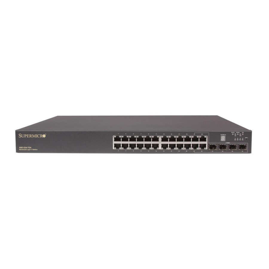
Ethernet switches. SSE-G24-TG4 Ports and Indicators Figure 4-1. SSE-G24-TG4 Ports and Indicators Front View Rear View Table 4-1. SSE-G24-TG4 Switch Module Ports and Indicators Item Description RJ-45 10/100/1000 Ethernet ports (24) SFP Combo Ports (4) LEDs and Stacking Indicator ID... -
Page 26: Sse-G48-Tg4 Ports And Indicators
Layer 2/3 1/10 Gigabit Ethernet Switches SSE-G48-TG4 Ports and Indicators Figure 4-2. Front View Rear View Table 4-2. SSE-G24-TG4 Switch Module Ports and Indicators Item Description RJ-45 10/100/1000 Ethernet ports (48) SFP Combo Ports (4) LEDs and Stacking Indicator ID... -
Page 27: Ports
Both Layer 2/3 1/10 Gigabit Ethernet switches contains several front mounted ports in common. RJ-45 Compatible Port These 24 (SSE-G24-TG4) or 48 (SSE-G48-TG4) 1-Gb/s duplex ports each accept an RJ-45 compatible cable. Combo Ports Each of the four SFP 1-Gb/s combo ports can hold a module for a downlinking fiber connector. -
Page 28: Power Port
This section covers LED indicators for the Layer 2/3 1/10 Gigabit Ethernet switches. These LEDs are listed and described in Table 4-3. Table 4-3. SSE-G24-TG4 LED Indicators LED Name Description Indicates this is the master switch in a stacked Master configuration. -
Page 29: Chapter 5 Web Based Management Utility
Port Number Ext */* – This is for an external port. Overview The Supermicro switch utility for Layer 2/3 1/10 Gigabit Ethernet switchess provides a web-based interface for managing Layer 2 and Layer 3 switching at wire speed for constructing a switched/routed network. This interface provides both a bridging functionality and advanced features such as link aggregation, Dynamic VLAN/Dynamic Multicast, IGMP Snooping and Network Access Control. -
Page 30: Nomenclature
ETTINGS in the System Management section. For the SSE-G48-TG44 and SSE-G24-TG4 switches, you can connect to any of the front panel 1G port or back panel 10G ports to manage the switch with the default management IP. These switches will create VLAN 1 by default with this IP address, including all 1G and 10G ports. -
Page 31: Login
Figure 5-1. Login Page The initial login page (Figure 5-1) is used to login to the Supermicro Switch web-based management utility for 10 Gp/s switches. To login, enter your User Name and Password in the fields provided and press the L button. -
Page 32: Home Page
(Figure 5-2) contains links and menus for going to all other control pages in the Supermicro Switch web-based interface utility. A list of controls for this page is shown in Table 5-1. The basic page structure of the H page is duplicated for all subsequent sub-pages of the Supermicro Switch web-based interface utility. - Page 33 The information in this page presents a brief overview of the switch web-based management utility. See Figure 5-3 Figure 5-4 for different views of the Home page for each of Supermico’s 10-Gb/s switches. Figure 5-3. SSE-G24-TG4 Home Page...
-
Page 34: Top Page Links
This part of the screen displays the Port Status, Speed and Link Status for every port of the switch. Since the number of ports is different in the SSE-G24-TG4 and SSE-G48-TG4 switches, this display displays a different number of ports for each when the Web Management... -
Page 35: Left Side Tree
Chapter 5: Web Based Management Utility • For the SSE-G24-TG4 switch, it displays twenty four Gi ports and four Ex ports. • For the SSE-G48-TG4 switch, it displays forty eight Gi ports and four Ex ports. Note that Ex ports configured as stacking ports will not be displayed. -
Page 36: System Management Page
Layer 2/3 1/10 Gigabit Ethernet Switches User’s Manual System Management Page Figure 5-5. System Management Page The S page (Figure 5-5) contains the following links: YSTEM ANAGEMENT • System Settings • System Version • File Management • Firmware Upgrade • Management Security •... -
Page 37: System Settings
Chapter 5: Web Based Management Utility System Settings Figure 5-6. System Settings Page Clicking the S tab brings up the S page (Figure 5-6). YSTEM NFORMATION YSTEM ETTINGS This page provides system related information and also helps you configure system specific parameters. -
Page 38: System Version
Layer 2/3 1/10 Gigabit Ethernet Switches User’s Manual Table 5-2. System Information Page Parameters (Continued) Parameter Description HTTP Server Status This is a display for the HTTP Server Status. HTTP Port Number This is a display for the HTTP Port Number. This page also has a control to Reset To Factory Defaults. -
Page 39: File Management
Chapter 5: Web Based Management Utility File Management Figure 5-8. File Management Page Clicking the F link brings up the F page (Figure 5-8). ANAGEMENT ANAGEMENT The F page helps you to manage the configuration files in the switch. ANAGEMENT This page provides three main features. -
Page 40: File Copy
Layer 2/3 1/10 Gigabit Ethernet Switches User’s Manual File Copy You can copy a local file to or from a remote TFTP server. This feature is useful to create a backup of configuration files remotely, and also to download configuration files from remote computers to the switch. -
Page 41: Management Security
Chapter 5: Web Based Management Utility Management Security The M link provides configuration for the following features: ANAGEMENT ECURITY • Management Security Basic Settings • Management User Account • Radius • TACACS+ Global Settings • TACACS+ Server Configuration • IP Authorized Manager •... - Page 42 Layer 2/3 1/10 Gigabit Ethernet Switches User’s Manual Table 5-3. Management Security Basic Settings Page Parameters Parameter Description Use this parameter to choose the mode of authentication for management access. By default the management access is authenticated with L user OCAL Authentication mode accounts information.
-
Page 43: Radius
Chapter 5: Web Based Management Utility Radius Figure 5-12. Radius Server Configuration Page Clicking the R tab brings up the R page ADIUS ADIUS ERVER ONFIGURATION (Figure 5-12). This page allows you to configure the RADIUS server parameters as shown in Table 5-4. -
Page 44: Tacacs+ Global Settings
Layer 2/3 1/10 Gigabit Ethernet Switches User’s Manual TACACS+ Global Settings Figure 5-13. TACACS+ Global Settings Page The TACACS+ G page (Figure 5-13) allows you to configure TACACS LOBAL ETTINGS retries and choose an active TACACS server. The parameters for this page are shown in Table 5-5. -
Page 45: Tacacs+ Server Configuration
Chapter 5: Web Based Management Utility TACACS+ Server Configuration Figure 5-14. TACACS+ Server Configuration Page Clicking the TACACS+ S tab brings up the TACACS+ S ERVERS ERVER ONFIGURATION page (Figure 5-14), which allows you to configure TACACS servers. The parameters for this page are shown in Table 5-6. -
Page 46: Ip Authorized Manager
Layer 2/3 1/10 Gigabit Ethernet Switches User’s Manual IP Authorized Manager Figure 5-15. IP Authorized Manager Page Clicking the IP A tab brings up the IP A page ANAGER UTHORIZED ANAGER (Figure 5-15), which allows you to configure allowed management nodes for managing the switch. -
Page 47: Ssh Configuration
Chapter 5: Web Based Management Utility SSH Configuration Figure 5-16. SSH Configuration Clicking the SSH (Secure Shell) tab brings up the SSH C page ONFIGURATION (Figure 5-16), which allows you to configure SSH version and keys. The parameters for this page are shown in Table 5-8. -
Page 48: Sslconfiguration
Layer 2/3 1/10 Gigabit Ethernet Switches User’s Manual SSLConfiguration Figure 5-17. SSL Configuraiton Page Clicking the SSL (Secure Socket Layers) tab brings up the SSL C page ONFIGURATION (Figure 5-17), which allows you to configure SSL parameters and generate SSL certificates for HTTPS. -
Page 49: Syslog
Chapter 5: Web Based Management Utility openssl x509 -req -in a.csr -out cert.pem -CA cacert.pem -CAkey cakey.pem -CAcreateserial The above steps will generate the certificate file cert.pem. 5. Open the generated certificate file cert.pem and delete the first line (---BEGIN CERTIFICATE ---) and last line (----END CERTIFICATE--). - Page 50 Layer 2/3 1/10 Gigabit Ethernet Switches User’s Manual Syslog Configuration Figure 5-18. Syslog Configuration Page Clicking the L tab brings up the S page (Figure 5-18), OGGING YSLOG ONFIGURATION which allows you to configure logging parameters. The parameters for this page are shown in Table 5-9.
-
Page 51: Acl
Chapter 5: Web Based Management Utility Syslog Mail Configuration Figure 5-19. Syslog Mail Configuration Page Clicking the M tab brings up the S page (Figure 5-19), YSLOG ONFIGURATION which allows you to configure the mail server and mail addresses for the syslog feature. The parameters for this page are shown in Table 5-10. - Page 52 Layer 2/3 1/10 Gigabit Ethernet Switches User’s Manual MAC Based ACL Figure 5-20. MAC ACL Configuration Page Clicking the M ACL tab brings up the M ACL C page (Figure 5-20), ONFIGURATION which displays the various parameters to configure the MAC Access List. The parameters for this page are shown in Table 5-11.
- Page 53 Chapter 5: Web Based Management Utility IP Standard ACL Figure 5-21. IP Standard ACL Configuration Page Clicking the IP S ACL (Access Control List) tab brings up the IP S TANDARD TANDARD page (Figure 5-21), which displays the various parameters to configure ONFIGURATION the Standard IP access lists.
- Page 54 Layer 2/3 1/10 Gigabit Ethernet Switches User’s Manual IP Extended ACL Figure 5-22. IP Extended ACL Page Clicking the IP E ACL tab brings up the IP E ACL C page XTENDED XTENDED ONFIGURATION (Figure 5-22), which displays the various parameters required to configure the Extended IP access lists.
- Page 55 Chapter 5: Web Based Management Utility Table 5-13. IP Extended ACL Configuration Page Parameters (Continued) Parameter Description Priority This parameter specifies the Priority for the filter. This parameter specifies the Type of Service for the access list. This parameter indicates the TCP Ack Bit to be checked against the incoming ACK Bit packet.
-
Page 56: Webgui Settings
Layer 2/3 1/10 Gigabit Ethernet Switches User’s Manual WEBGUI Settings Figure 5-23. Web GUI Settings Page Clicking the W link brings up the W GUI S page (Figure 5-23), ETTINGS ETTINGS which displays all basic Web GUI settings. The parameters for this page are shown in Table 5-14. -
Page 57: Snmp
Chapter 5: Web Based Management Utility SNMP Figure 5-24. SNMP Agent Control Settings Page Clicking the SNMP link brings up the SNMP A page GENT ONTROL ETTINGS (Figure 5-24). SMIS supports the SNMP Agent or SNMP AgentX Sub-agent. The SNMP Agent or AgentX Sub-agent can be enabled or both can be disabled. The SNMP Agent provides the following sub-page configurations shown in the table below. - Page 58 Layer 2/3 1/10 Gigabit Ethernet Switches User’s Manual Table 5-15. SNMP Agent Configuration Pages (Continued) Configuration Description Page This setting allows you to configure SNMP target parameters including SNMP Target , MP M and S ARAMETER ODEL ECURITY ODEL EVEL TORAGE Parameter Settings This setting allows you to configure SNMP security including user name,...
-
Page 59: Snmp Community Settings
Chapter 5: Web Based Management Utility SNMP Community Settings Figure 5-25. SNMP Community Settings Page Clicking the C tab brings up the SNMP C page OMMUNITY OMMUNITY ETTINGS (Figure 5-25), which allows you to add SNMP managers or remove existing managers.. The parameters for this page are shown in Table 5-16. -
Page 60: Snmp Group Settings
Layer 2/3 1/10 Gigabit Ethernet Switches User’s Manual SNMP Group Settings Figure 5-26. SNMP Group Settings Page Clicking the G tab brings up the SNMP G page (Figure 5-26). This ROUP ROUP ETTINGS page helps you map a combination of the S and the S into ECURITY... -
Page 61: Snmp Group Access Settings
Chapter 5: Web Based Management Utility SNMP Group Access Settings Figure 5-27. SNMP Group Access Settings Page Clicking the G tab brings up the SNMP G page ROUP CCESS ROUP CCESS ETTINGS (Figure 5-27), which displays the access rights of groups. Each entry is indexed by a , a Context Prefix, a S and a S . -
Page 62: Snmp View Tree Settings
Layer 2/3 1/10 Gigabit Ethernet Switches User’s Manual Table 5-18. SNMP Group Access Settings Page Parameters (Continued) Parameter Description Notify View This parameter allows you to specify the N identifier. OTIFY Use this parameter to specify whether the S is volatile or TORAGE Storage Type non-volatile. -
Page 63: Snmp Target Address Settings
Chapter 5: Web Based Management Utility Table 5-19. SNMP View Tree Settings Page Parameters (Continued) Parameter Description View Type This parameter specifies whether a V is Included or Excluded. Use this parameter to specify whether the S is volatile or TORAGE Storage Type non-volatile. -
Page 64: Snmp Target Parameter Settings
Layer 2/3 1/10 Gigabit Ethernet Switches User’s Manual Table 5-20. SNMP Target Address Settings Page Parameters (Continued) Parameter Description contains SNMP parameters to be used when generating messages to be ARAM Param sent to a transport address. Use this parameter to specify whether the S is volatile or TORAGE Storage Type... -
Page 65: Snmp User Settings
Chapter 5: Web Based Management Utility Table 5-21. SNMP Target Parameter Settings Page Parameters (Continued) Parameter Description specifies the level of security used when generating SNMP ECURITY EVEL Security Level messages. Storage Type can be configured as Volatile or Non-Volatil TORAGE SNMP User Settings Figure 5-31. -
Page 66: Snmp Trap Settings
Layer 2/3 1/10 Gigabit Ethernet Switches User’s Manual Table 5-22. SNMP Security Settings Page Parameters (Continued) Parameter Description is an indication of whether or not messages sent on behalf of this RIVACY Privacy Key user to/from the SNMP are protected from disclosure. Storage Type can be configured as Volatile or Non-volatile. -
Page 67: Snmp Agentx
Chapter 5: Web Based Management Utility SNMP AgentX Figure 5-33. SNMP AgentX Subagent Settings Page Clicking the A X link brings up the SNMP A page GENT GENT UBAGENT ETTINGS (Figure 5-33), which allows you to configure SNMP Agentx sub-agent parameters. The parameters for this page are shown in Table 5-24. -
Page 68: Rmon
Layer 2/3 1/10 Gigabit Ethernet Switches User’s Manual RMON The following pages can be used to set RMON (Remote Monitoring) features and settings: • RMON Basic Settings • Event Configuration • RMON Alarm Configuration • Ethernet Statistics Configuration • History Control Configuration RMON Basic Settings Figure 5-34. -
Page 69: Event Configuration
Chapter 5: Web Based Management Utility Event Configuration Figure 5-35. Event Configuration Settings Page Clicking the E tab brings up the E page (Figure 5-35), which VENTS VENT ONFIGURATIONS configures RMON events. The parameters for this page are shown in Table 5-25. -
Page 70: Rmon Alarm Configuration
Layer 2/3 1/10 Gigabit Ethernet Switches User’s Manual RMON Alarm Configuration Figure 5-36. RMON Alarm Configuration Page Clicking the A tab brings up the RMON A page (Figure 5-36), LARM LARM ONFIGURATION which configures RMON Alarm paramters. The parameters for this page are shown in Table 5-26. -
Page 71: Ethernet Statistics Configuration
Chapter 5: Web Based Management Utility Ethernet Statistics Configuration Figure 5-37. Ethernet Statistics Configuration Page Clicking the E tab brings up the E THERNET TATISTICS THERNET TATISTICS page (Figure 5-37), which configures RMON Ethernet statistics ONFIGURATION parameters. The parameters for this page are shown in Table 5-27. -
Page 72: History Control Configuration
Layer 2/3 1/10 Gigabit Ethernet Switches User’s Manual History Control Configuration Figure 5-38. History Control Configuration Page Clicking the H tab brings up the H page ISTORY ISTORY ONTROL ONFIGURATION (Figure 5-38), which configures RMON history configuration parameters. The parameters for this page are shown in Table 5-28. -
Page 73: Qos
Chapter 5: Web Based Management Utility The QoS link of the System page opens the QoS Basic Settings page. This page allows you to configure QoS through following pages: • QOS Basic Settings • QOS Classmap Settings • QOS Policymap Settings •... - Page 74 Layer 2/3 1/10 Gigabit Ethernet Switches User’s Manual QOS Classmap Settings Figure 5-40. QOS Classmap Settings Page Clicking the C tab brings up the QOS C page (Figure 5-40), LASSMAP LASSMAP ETTINGS which is used to classify the stream of traffic. The parameters for this page are shown in Table 5-30.
- Page 75 Chapter 5: Web Based Management Utility QOS Policymap Settings Figure 5-41. QOS Policymap Settings Page Clicking the P tab brings up the QOS P page (Figure 5-41), OLICYMAP OLICYMAP ETTINGS which is used to specify action for a specified classmap. The parameters for this page are shown in Table 5-31.
-
Page 76: Cosq Scheduling Algorithm
Layer 2/3 1/10 Gigabit Ethernet Switches User’s Manual COSQ Scheduling Algorithm Figure 5-42. COSQ Scheduling Algorithm Settings Page Clicking the C (Class of Service Queue Algorithm) tab brings up the LGORITHM COSQ S page (Figure 5-42), which allows you to CHEDULING LGORITHM ETTINGS... -
Page 77: Cosq Weight And Bandwidth Configuration
Chapter 5: Web Based Management Utility COSQ Weight and Bandwidth Configuration Figure 5-43. COSQ Weight and Bandwidth Configurations Page Clicking the C tab brings up the COSQ W RAFFIC LASS EIGHT AND ANDWIDTH page (Figure 5-43), which allows you to configure the weight and ONFIGURATIONS bandwidth for CoS Queues. -
Page 78: Ntp Settings
Layer 2/3 1/10 Gigabit Ethernet Switches User’s Manual NTP Settings Figure 5-44. NTP Settings Page Clicking the NTP link brings up the NTP S page (Figure 5-44), which configures ETTINGS the Network Time Protocol (NTP). The parameters for this page are shown in Table 5-34. -
Page 79: Stack
NTP servers. Stack The Supermicro Intelligent switch supports stacking of Supermicro switch units. Switch stacking is created by connecting switches in a daisy chain. One of the stacked switches is selected as a Master based on its configurations. The Master switch provides management support for the whole stack. - Page 80 Layer 2/3 1/10 Gigabit Ethernet Switches User’s Manual The interface numbers change between stacking and non-stacking cases due to the switch ID. So configurations saved for stacking are not valid for non-stacking cases and vice versa. NOTE: If you choose stacking using the stack command from a non-stacking case, and the configurations are already saved for restoring the switch, it will rename the configuration file by adding a suffix _nonstack and will not restore this file when the switch reboots with stacking enabled.
-
Page 81: Stack Configuration
Chapter 5: Web Based Management Utility NOTE: In a stack only one switch can be configured as master. Otherwise the slave switches will not allow you to configure anything except stacking disabled. To login to slave switches, use a login name as "stackuser" and password as "stack123". - Page 82 Layer 2/3 1/10 Gigabit Ethernet Switches User’s Manual Stack Configuration Figure 5-46. Stack Configuration Page Clicking the S tab brings up the S page TACK ETTINGS TACK ONFIGURATION (Figure 5-46), which configures the stacking feature. The parameters for this page are shown in Table 5-35.
- Page 83 Chapter 5: Web Based Management Utility Stack Details Figure 5-47. Stack Details Page Clicking the S tab brings up the S page (Figure 5-47), which TACK ETAILS TACK ETAILS displays stacking details. The parameters for this page are shown in Table 5-36.
- Page 84 Layer 2/3 1/10 Gigabit Ethernet Switches User’s Manual Table 5-36. Stack Details Page Parameters (Continued) Parameter Description This parameter is used to specify the MAC address of the Slave switch. This Stack MAC MAC address is used to communicate between stack member switches. Switch State This parameter is used to specify the current status of the Slave switch.
- Page 85 Chapter 5: Web Based Management Utility Table 5-37. Stack Counter Details Page Parameters (Continued) Parameter Description InHCOctet This parameter displays the number of bytes received with HC. Transmit Statistics OutOctet This parameter displays the number of bytes transmitted. OutUcast This parameter displays the number of unicast packets transmitted. OutDiscard This parameter displays the number of packets discarded in transmission.
-
Page 86: Layer 2 Management
Layer 2/3 1/10 Gigabit Ethernet Switches User’s Manual Layer 2 Management The L page (Figure 5-49) has links to all pages with Layer2 controls. AYER ANAGEMENT Figure 5-49. Layer2 Management Page 5-58... -
Page 87: Layer 2 Basic Settings
Chapter 5: Web Based Management Utility Layer 2 Basic Settings Figure 5-50. MAC Address Table Settings Page Clicking the L link brings up the MAC A AYER ASIC TTINGS DDRESS ABLE ETTINGS page (Figure 5-50), which gives you the option to change MAC aging time. MAC address confirmation can be done with this time interval. -
Page 88: Port Manager
Layer 2/3 1/10 Gigabit Ethernet Switches User’s Manual Port Manager The P link has links to the following web pages: ANAGER • Port Basic Settings • Port Monitoring • VLAN Traffic Class • Port Control • Rate Limiting NOTE: In all port based configuration pages, the port number group links are provided on the top. - Page 89 Chapter 5: Web Based Management Utility Port Basic Settings Figure 5-51. Port Basic Settings Page Clicking the B tab brings up the P page (Figure 5-51), ASIC ETTINGS ASIC ETTINGS which allows you to configure port status and mode information. This page also helps configuring priority and MTU.
-
Page 90: Port Monitoring
Layer 2/3 1/10 Gigabit Ethernet Switches User’s Manual Port Monitoring Figure 5-52. Port Monitoring Page Clicking the P tab brings up the P page (Figure 5-52), ONITORING ONITORING which allows you to enable or disbale monitoring on port interface. The parameters for this page are shown in Table 5-39. -
Page 91: Vlan Traffic Class
Chapter 5: Web Based Management Utility VLAN Traffic Class Figure 5-53. VLAN Traffic Class Mapping Page Clicking the T tab brings up the VLAN T page RAFFIC LASS RAFFIC LASS APPING (Figure 5-53), which allows you to map a priority to a traffic class. The parameters for this page are shown in Table 5-40. -
Page 92: Port Control
Layer 2/3 1/10 Gigabit Ethernet Switches User’s Manual Port Control Figure 5-54. Port Control Page Clicking the P tab brings up the P page (Figure 5-54), which ONTROL ONTROL allows you to configure specific parameters of the port. You can choose between Auto-negotiation and No-negotiation for a port. -
Page 93: Rate Limiting
Chapter 5: Web Based Management Utility Rate Limiting Figure 5-55. Rate Limiting Page Clicking the R tab brings up the R page (Figure 5-55), which IMITING IMITING allows you to configure rate limiting for the port interface. The parameters for this page are shown in Table 5-42. -
Page 94: Vlan
Layer 2/3 1/10 Gigabit Ethernet Switches User’s Manual VLAN The VLAN link allows to configure the VLAN information. VLAN configuration information has been provided in the following pages: • VLAN Basic Settings • Port Settings • Static VLAN • Protocol Group •... - Page 95 Chapter 5: Web Based Management Utility Table 5-43. VLAN Basic Settings Page Parameters Parameter Description Garp System Control This parameter starts or shuts down GARP in the switch. This parameter specifies the Learning Mode (Independent, Shared, Hybrid or Learning Mode VLAN Learning).
-
Page 96: Port Settings
Layer 2/3 1/10 Gigabit Ethernet Switches User’s Manual Port Settings Figure 5-57. VLAN Port Settings Page Clicking the P tab brings up the VLAN P page (Figure 5-57), ETTINGS ETTINGS which is used to associate the VLAN ID to the port for Port based VLAN classification. While associating different ports to VLANs, you can also configure I NGRESS ILTERING... -
Page 97: Static Vlan
Chapter 5: Web Based Management Utility Static VLAN Figure 5-58. Static VLAN Configuration Page Clicking the S VLAN tab brings up the S VLAN C page TATIC TATIC ONFIGURATION (Figure 5-58), which allows you to configure the VLAN related information statically. Using the first table you can create new entries for uncreated VLANs. -
Page 98: Protocol Group
Layer 2/3 1/10 Gigabit Ethernet Switches User’s Manual Protocol Group Figure 5-59. VLAN Protocol Group Settings Page Clicking the P tab brings up the VLAN P ROTOCOL ROUP ROTOCOL ROUP ETTINGS page (Figure 5-59), which is used to map Protocol Templates to Protocol Group Identifiers. -
Page 99: Vlan Port Mac Map
Chapter 5: Web Based Management Utility Vlan Port MAC Map Figure 5-60. VLAN Port MAC Map Settings Page Clicking the P tab brings up the VLAN P MAC M page (Figure 5-60), which allows you to configure MAC based VLANs. The parameters for this page are shown in Table 5-44. -
Page 100: Unicast Mac
Layer 2/3 1/10 Gigabit Ethernet Switches User’s Manual Unicast MAC Figure 5-61. VLAN Unicast MAC Settings Page Clicking the U MAC tab brings up the VLAN U page NICAST NICAST ETTINGS (Figure 5-61), which allows you to configure the various parameters for VLAN Unicast MAC settings. -
Page 101: Wildcard
Chapter 5: Web Based Management Utility Wildcard Figure 5-62. Wildcard Settings Page Clicking the W tab brings up the W page (Figure 5-62), which ILDCARD ILDCARD ETTINGS configures wildcard MAC addresses and ports for VLANs. The parameters for this page are shown in Table 5-46. -
Page 102: Switch Port Vlan
Layer 2/3 1/10 Gigabit Ethernet Switches User’s Manual Switch Port VLAN Figure 5-63. SwitchPort Vlan Filtering Page Clicking the S tab brings up the S WITCH ILTERING WITCH ILTERING page (Figure 5-63), which configures utility criteria for SwitchPort Vlan filtering. The parameters for this page are shown in Table 5-47. -
Page 103: Dynamic Vlan
Chapter 5: Web Based Management Utility Dynamic Vlan The Dynamic VLAN link allows you to configure the Dynamic VLAN information. Dynamic VLAN configuration information has been provided in the following pages • Dynamic VLAN Global Configuration • Port Configuration • GARP Timers Dynamic VLAN Global Configuration Figure 5-64. -
Page 104: Port Configuration
Layer 2/3 1/10 Gigabit Ethernet Switches User’s Manual Port Configuration Figure 5-65. Dynamic VLAN Port Configuration Page Clicking the P link brings up the D VLAN P ETTINGS YNAMIC ONFIGURATION page (Figure 5-65), which allows you to configure parameters for Dynamic VLAN ports. The parameters for this page are shown in Table 5-48. -
Page 105: Garp Timers
Chapter 5: Web Based Management Utility GARP Timers Figure 5-66. Garp Timers Configuration Page Clicking the G tab brings up the G page IMERS IMERS ONFIGURATION (Figure 5-66), which displays the various parameters for changing Garp times. The parameters for this page are shown in Table 5-49. -
Page 106: Rstp
Layer 2/3 1/10 Gigabit Ethernet Switches User’s Manual RSTP The RSTP link provides links to the following configuration pages: • RSTP Global Settings • RSTP Basic Settings • Port Settings • Port Status RSTP Global Settings Figure 5-67. Global Configuration Page Clicking the G tab brings up the G page... - Page 107 Chapter 5: Web Based Management Utility RSTP Basic Settings Figure 5-68. RSTP Configuration Page Clicking the B tab brings up the RSTP C page (Figure 5-68), ASIC ETTINGS ONFIGURATION which displays the various parameters for RSTP configuration. The parameters for this page are shown in Table 5-51.
- Page 108 Layer 2/3 1/10 Gigabit Ethernet Switches User’s Manual Port Settings Figure 5-69. Port Status Configuration Page Clicking the P tab brings up the P page ETTINGS TATUS ONFIGURATION (Figure 5-69), which allows you to set the configuration per port related to RSTP. The parameters for this page are shown in Table 5-52.
-
Page 109: Port Status
Chapter 5: Web Based Management Utility Port Status Figure 5-70. RSTP Port Status Page Clicking the P tab brings up the RSTP P page (Figure 5-70), TATUS TATUS which displays RSTP port specific information. The parameters for this page are shown Table 5-53. -
Page 110: Mstp
Layer 2/3 1/10 Gigabit Ethernet Switches User’s Manual MSTP The MSTP link leads you to the following configuration pages: • MSTP Basic Settings • MSTP Timers • Port Configuration • VLAN Mapping • Port Settings • CIST Port Status MSTP Basic Settings Figure 5-71. -
Page 111: Mstp Timers
Chapter 5: Web Based Management Utility Table 5-54. Global Configuration Page Parameters (Continued) Parameter Description This parameter specifies the Priority value assigned to the bridge that is used to Bridge Priority select the root bridge. This parameter specifies the maximum number of packets that can be sent in a Transmit Hold Count given interval. -
Page 112: Port Configuration
Layer 2/3 1/10 Gigabit Ethernet Switches User’s Manual Port Configuration Figure 5-73. CIST Settings Page Clicking the P tab brings up the CIST S page (Figure 5-73), ONFIGURATION ETTINGS which sets the configuration per Port related to MSTP. The parameters for this page are shown in Table 5-55. -
Page 113: Vlan Mapping
Chapter 5: Web Based Management Utility Table 5-55. CIST Settings Page Parameters (Continued) Parameter Description Restricted Role This parameter specifies the Restricted role status of the port. Restricted TCN This parameter indicates the Restricted TCN status of the port. VLAN Mapping Figure 5-74. -
Page 114: Port Settings
Layer 2/3 1/10 Gigabit Ethernet Switches User’s Manual Port Settings Figure 5-75. Port Settings Page Clicking the P tab brings up the P page (Figure 5-75), which ETTINGS ETTINGS displays the various parameters for port settings. The parameters for this page are shown in Table 5-57. -
Page 115: Cist Port Status
Chapter 5: Web Based Management Utility CIST Port Status Figure 5-76. MSTP CIST Port Status Page Clicking the CIST P tab brings up the MSTP CIST P page TATUS TATUS (Figure 5-76), which displays MSTP CIST port specific information. The parameters for this page are shown in Table 5-58. -
Page 116: La Basic Settings
Layer 2/3 1/10 Gigabit Ethernet Switches User’s Manual Table 5-58. MSTP CIST Port Status Page Parameters (Continued) Parameter Description This parameter specifies the ports current role as defined by the Spanning Tree Role Protocol. This parameter specifies the port's current state as defined by the application of Port State the Spanning Tree Protocol. -
Page 117: Interface Settings
Chapter 5: Web Based Management Utility Table 5-59. LA Basic Settings Page Parameters Parameter Description System Control This parameter Starts or Shutsdown LA in the switch. LA Status This is used to enable or disable LA in the switch. System Priority This parameter specifies the priority value associated with the Actor's system ID. -
Page 118: Port Channel
Layer 2/3 1/10 Gigabit Ethernet Switches User’s Manual Port Channel Figure 5-79. LA Port Channel Settings Page Clicking the P tab brings up the LA P HANNEL ETTINGS HANNEL ETTINGS page (Figure 5-79), which is used to edit the Port Channel configuration. The first table is for creating Port Channel interfaces while the second table is for editing the Port Channel configuration. -
Page 119: Port Settings
Chapter 5: Web Based Management Utility Port Settings Figure 5-80. LA Port Settings Page Clicking the P tab brings up the LA P page (Figure 5-80), ETTINGS ETTINGS which configures LA properties at a per-port level. The parameters for this page are shown in Table 5-62. -
Page 120: Port State Info
Layer 2/3 1/10 Gigabit Ethernet Switches User’s Manual Table 5-62. LA Port Settings Page Parameters (Continued) Parameter Description This parameter configures the waiting time for a port after receiving Partner Wait Time information and before entering aggregation. This parameter indicates the current state of the port with respect to Link Aggregation. -
Page 121: Load Balancing
Chapter 5: Web Based Management Utility Load Balancing Figure 5-82. LA Load Balancing Policy Page Clicking the L tab brings up the LA L page ALANCING ALANCING OLICY (Figure 5-82), which allows you to choose the selection policy for load distribution on the aggregated links. -
Page 122: Basic Settings
Layer 2/3 1/10 Gigabit Ethernet Switches User’s Manual Basic Settings Figure 5-83. 802.1x Basic Settings Page Clicking the B tab brings up the 802.1 page ASIC ETTINGS ASIC ETTINGS (Figure 5-83), which displays the various 802.1x Basic Settings parameters. The parameters for this page are shown in Table 5-63. -
Page 123: Port Settings
Chapter 5: Web Based Management Utility Port Settings Figure 5-84. 802.1x Port Settings Page Clicking the P tab brings up the 802.1 page ETTINGS ETTINGS (Figure 5-84), which configures security information at the individual port levels. The parameters for this page are shown in Table 5-64. - Page 124 Layer 2/3 1/10 Gigabit Ethernet Switches User’s Manual Table 5-64. 802.1x Port Settings Page Parameters (Continued) Parameter Description This parameter specifies the initialization control for the port. Setting this value to Port Initialize True causes the port to be initialized. The value reverts to False once initialization is complete.
-
Page 125: Timers
Chapter 5: Web Based Management Utility Timers Figure 5-85. 802.1x Timer Configuration Page Clicking the T tab brings up the 802.1 page (Figure 5-85), IMERS IMER ONFIGURATION which configures Timer parameters at the individual port level. The parameters for this page are shown in Table 5-13. -
Page 126: Local As
Layer 2/3 1/10 Gigabit Ethernet Switches User’s Manual Local AS Figure 5-86. Local Authentication Server Configuration Page Clicking the L AS tab brings up the L OCAL OCAL UTHENTICATION ERVER ONFIGURATION page (Figure 5-20), which configures Local Authentication Server information. The parameters for this page are shown in Table 5-13. -
Page 127: Mac Session Info
Chapter 5: Web Based Management Utility MAC Session Info Figure 5-87. MAC Session Info Page Clicking the MAC S tab brings up the MAC S page ESSION ESSION (Figure 5-20), which configures the supplicant MAC address. The parameters for this page are shown in Table 5-13. - Page 128 Layer 2/3 1/10 Gigabit Ethernet Switches User’s Manual Unicast Filters Figure 5-88. L2 Unicast Filter Configuration Page Clicking the U tab brings up the L2 U page NICAST ILTERS NICAST ILTER ONFIGURATION (Figure 5-20), which sets the filter configuration to control the unicast packets that the switch needs to process.
- Page 129 Chapter 5: Web Based Management Utility Multicast Filters Figure 5-89. L2 Multicast Filter Configuration Page Clicking the M tab brings up the L2 M ULTICAST ILTERS ULTICAST ILTER ONFIGURATION page (Figure 5-20), which allows you to set the filter configuration to control the multicast packets that the switch needs to process.
-
Page 130: Layer 3 Management
Layer 2/3 1/10 Gigabit Ethernet Switches User’s Manual Layer 3 Management Figure 5-90. Layer3 Management Page The L home page (Figure 5-90) has links to all Layer 3 features. AYER ANAGEMENT The IP link enables you to perform IP related configuration. This can be done through the following pages. - Page 131 Chapter 5: Web Based Management Utility Vlan Interface Figure 5-91. VLAN Interface Basic Settings Page Clicking the VLAN I tab brings up the VLAN I page NTERFACE NTERFACE ASIC ETTINGS (Figure 5-91), which allows configuring of L3 VLAN interfaces. The parameters for this page are shown in Table 5-70.
- Page 132 Layer 2/3 1/10 Gigabit Ethernet Switches User’s Manual IP V4 Interface Settings Figure 5-92. IPv4 Interface Settings Page Clicking the IP tab brings up the IP page NTERFACE ETTINGS (Figure 5-92), which allowsyou to configure the IP address for L3 VLANs. The parameters for this page are shown in Table 5-71.
-
Page 133: Ip Route
Chapter 5: Web Based Management Utility IP Route Figure 5-93. IP Route Configuration Page Clicking the IP R tab brings up the IP R page (Figure 5-93), OUTE OUTE ONFIGURATION which allows you to configure the static IP routes. The parameters for this page are shown in Table 5-72. -
Page 134: Loopback Basic Settings
Layer 2/3 1/10 Gigabit Ethernet Switches User’s Manual LoopBack Basic Settings Figure 5-94. LoopBack Basic Settings Page Clicking the L tab brings up the L page ETTINGS ASIC ETTINGS (Figure 5-94), which allows you to configure loopback IP interfaces. The parameters for this page are shown in Table 5-73. - Page 135 Chapter 5: Web Based Management Utility • Address Profile • Prefix Settings IPv6 Route Configuration Figure 5-95. IP6 Route Configuration Page Clicking the IP tab brings up the IP6 R page OUTE OUTE ONFIGURATION (Figure 5-95), which configures various IP6 Route parameters. The parameters for this page are shown in Table 5-74.
-
Page 136: Ipv6 Interface
Layer 2/3 1/10 Gigabit Ethernet Switches User’s Manual IPv6 Interface Figure 5-96. IPv6 Interface Settings Page Clicking the IP tab brings up the IP page NTERFACE NTERFACE ETTINGS (Figure 5-96), which displays the various parameters for the IPv6 Interface. The parameters for this page are shown in Table 5-75. -
Page 137: Nd Cache
Chapter 5: Web Based Management Utility Table 5-75. IPv6 Interface Settings Page Parameters (Continued) Parameter Description This parameter specifies the minimum time in seconds allowed between sending RA Min unsolicited router advertisements. This parameter indicates the maximum time in seconds allowed between RA Max sending unsolicited router advertisements. -
Page 138: Address Settings
Layer 2/3 1/10 Gigabit Ethernet Switches User’s Manual Address Settings Figure 5-98. Address Settings Page Clicking the A tab brings up the A page DDRESS ETTINGS DDRESS ETTINGS (Figure 5-98), which allows you to configure address settings for IPv6. The parameters for this page are shown in Table 5-77. -
Page 139: Address Profile
Chapter 5: Web Based Management Utility Address Profile Figure 5-99. Address Profile Settings Page Clicking the A tab brings up the A page DDRESS ROFILE DDRESS ROFILE ETTINGS (Figure 5-99). The parameters for this page are shown in Table 5-78. Table 5-78. -
Page 140: Prefix Settings
Layer 2/3 1/10 Gigabit Ethernet Switches User’s Manual Prefix Settings Figure 5-100. Prefix Configuration Page Clicking the P tab brings up the P page REFIX ETTINGS REFIX ONFIGURATION (Figure 5-100). The parameters for this page are shown in Table 5-79. Table 5-79. - Page 141 Chapter 5: Web Based Management Utility DHCP Basic Settings Figure 5-101. DHCP Basic Settings Page Clicking the DHCP S tab brings up the DHCP B page ETTINGS ASIC ETTINGS (Figure 5-101). The parameters for this page are shown in Table 5-80.
-
Page 142: Pool Settings
Layer 2/3 1/10 Gigabit Ethernet Switches User’s Manual Pool Settings Figure 5-102. DHCP Pool Settings Page Clicking the P link brings up the DHCP P page (Figure 5-102), ETTINS ETTINGS which allows you to configure the IP address pool that can be used by the DHCP server to allocate IP addresses. -
Page 143: Dhcp Relay
Chapter 5: Web Based Management Utility DHCP Relay The DHCP Relay link helps you to manage the DHCP relay in the switch through the following two pages: • DHCP Relay Basic Settings • Interface Settings DHCP Relay Basic Settings Figure 5-103. DHCP Relay Configuration Page Clicking the B tab brings up the DHCP R page... -
Page 144: Interface Settings
Layer 2/3 1/10 Gigabit Ethernet Switches User’s Manual Interface Settings Figure 5-104. DHCP Relay Interface Configuration Page Clicking the I tab brings up the DHCP R NTERFACE ELAY NTERFACE ONFIGURATION page (Figure 5-104), which allows you to configure the DHCP relay for VLANs. The parameters for this page are shown in Table 5-83. - Page 145 Chapter 5: Web Based Management Utility RIP Basic Settings Figure 5-105. RIP Basic Settings Page Clicking the B tab brings up the RIP B page (Figure 5-105). ASIC ETTINGS ASIC ETTINGS The parameters for this page are shown in Table 5-84.
-
Page 146: Interfaces
Layer 2/3 1/10 Gigabit Ethernet Switches User’s Manual Interfaces Figure 5-106. RIP Interface Page Clicking the I tab brings up the RIP I page (Figure 5-106). The NTERFACE NTERFACE parameters for this page are shown in Table 5-85. Table 5-85. RIP Interface Page Parameters Parameter Description Interface... -
Page 147: Neighbors List
Chapter 5: Web Based Management Utility Neighbors List Figure 5-107. RIP Neighbor List Page Clicking the N tab brings up the RIP N page (Figure 5-107), which EIGHBORS EIGHBOR is used to configure the RIP neighbors, by configuring their IP address. The single parameter for this page is IP A , which specifies the IP Address of the DDRESS... -
Page 148: Security Settings
Layer 2/3 1/10 Gigabit Ethernet Switches User’s Manual Security Settings Figure 5-108. RIP Security Settings Page Clicking the S tab brings up the RIP S page (Figure 5-108). The ECURITY ECURITY ETTING parameters for this page are shown in Table 5-13. -
Page 149: Address Summarization
Chapter 5: Web Based Management Utility Address Summarization Figure 5-109. RIP Interface Specific Address Summarization Page Clicking the S tab brings up the RIP I UMMARIZATION NTERFACE PECIFIC DDRESS page (Figure 5-109). The parameters for this page are shown in UMMARIZATION Table 5-87. -
Page 150: Rip6 Interface
Layer 2/3 1/10 Gigabit Ethernet Switches User’s Manual RIP6 Interface Figure 5-110. RIP6 Interface Configuration Page Clicking the RIP6 I tab brings up the RIP6 I page NTERFACE NTERFACE ONFIGURATION (Figure 5-110). The parameters for this page are shown in Table 5-88. -
Page 151: Filters
Chapter 5: Web Based Management Utility Filters Figure 5-111. RIP6 Filter Configuration Page Clicking the F tab brings up the RIP6 F page (Figure 5-111). ILTERS ILTER ONFIGURATION The parameters for this page are shown in Table 5-89. Table 5-89. RIP6 Filter Configuration Page Parameters Parameter Description Filter Address... - Page 152 Layer 2/3 1/10 Gigabit Ethernet Switches User’s Manual OSPF Basic Settings Figure 5-112. OSPF Basic Settings Page Clicking the B tab brings up the OSPF B page ASIC ETTINGS ASIC ETTINGS (Figure 5-112). The parameters for this page are shown in Table 5-90.
-
Page 153: Area
Chapter 5: Web Based Management Utility Area Figure 5-113. OSPF Area Configuration Page Clicking the A tab brings up the OSPF A page (Figure 5-113). ONFIGURATION The parameters for this page are shown in Table 5-91. Table 5-91. OSPF Area Configuration Page Parameters Parameter Description Area ID... -
Page 154: Interface
Layer 2/3 1/10 Gigabit Ethernet Switches User’s Manual Interface Figure 5-114. OSPF Interface Configuration Page Clicking the I tab brings up the OSPF I page NTERFACE NTERFACE ONFIGURATION (Figure 5-114). The parameters for this page are shown in Table 5-92. Table 5-92. -
Page 155: Virtual Interface
Chapter 5: Web Based Management Utility Virtual Interface Figure 5-115. OSPF Virtual Interface Configuration Page Clicking the V tab brings up the OSPF V IRTUAL NTERFACE IRTUAL NTERFACE page (Figure 5-115). The parameters for this page are shown in ONFIGURATION Table 5-93. -
Page 156: Ospf Neighbor
Layer 2/3 1/10 Gigabit Ethernet Switches User’s Manual OSPF Neighbor Figure 5-116. OSPF Neighbor Configuration Page Clicking the N tab brings up the OSPF N page EIGHBOR EIGHBOR ONFIGURATION (Figure 5-116), which allows you to configure OSPF neighbors. The parameters for this page are shown in Table 5-94. -
Page 157: Ospf Rrd Route Configuration
Chapter 5: Web Based Management Utility OSPF RRD Route Configuration Figure 5-117. OSPF RRD Route Configuration Page Clicking the RRD R tab brings up the OSPF RRD R page OUTE OUTE ONFIGURATION (Figure 5-117), which displays the various parameters for RRD Route configuration. The parameters for this page are shown in Table 5-95. -
Page 158: Ospf Area Aggregation
Layer 2/3 1/10 Gigabit Ethernet Switches User’s Manual OSPF Area Aggregation Figure 5-118. OSPF Area Aggregation Page Clicking the A tab brings up the OSPF A page GGREGATION GGREGATION (Figure 5-118). The parameters for this page are shown in Table 5-96. -
Page 159: External Aggregation
Chapter 5: Web Based Management Utility External Aggregation Figure 5-119. OSPF As External Aggregation Configuration Page Clicking the E tab brings up the OSPF A GGREGATION XTERNAL GGREGATION page (Figure 5-119), which allows you to configure OSPF external ONFIGURATION aggregation parameters. The parameters for this page are shown in Table 5-97. - Page 160 Layer 2/3 1/10 Gigabit Ethernet Switches User’s Manual Table 5-97. OSPF As External Aggregation Configuration Page Parameters Parameter Description This parameter specifies the Aggreation option as one of the following: • Advertise – When set to advertise and associated Area ID is 0.0.0.0, then the aggregated Type-5 are generated.
-
Page 161: Ospf V3
Chapter 5: Web Based Management Utility OSPF V3 The OSPFv3 link allows you to configure the OSPFv3 protocol through the following pages: • OSPFv3 Basic Settings • Interface • Area • OSPF V3 External Aggregation OSPFv3 Basic Settings Figure 5-120. OSPFv3 Basic Settings Page Clicking the B tab brings up the OSPF page... -
Page 162: Interface
Layer 2/3 1/10 Gigabit Ethernet Switches User’s Manual Table 5-98. OSPFv3 Basic Settings Page Parameters (Continued) Parameter Description This parameter specifies maximum number of non-default AS-external-LSAs External LSDB Limit entries that can be stored in the link-state database. This parameter specifies the time interval in seconds a router will attempt to Exit Overflow Interval leave OverflowState. - Page 163 Chapter 5: Web Based Management Utility Table 5-99. Interface Settings Page Parameters Parameter Description VLAN/Tunnel This parameter specifies the IPv6 interface over which OSPFv3 is enabled. Identifier Area ID This parameter specifies the area ID associated with the IPv6 interface. This parameter specifies the type of OSPFv3 interface (broadcast, nbma, Interface Type pointToPoint and pointToMultipoint).
-
Page 164: Area
Layer 2/3 1/10 Gigabit Ethernet Switches User’s Manual Area Figure 5-122. OSPFv3 Area Settings Page Clicking the A tab brings up the OSPF page (Figure 5-122). The ETTINGS parameters for this page are shown in Table 5-100. Table 5-100. OSPFv3 Area Settings Page Parameters Parameter Description Area ID... -
Page 165: Ospf V3 External Aggregation
Chapter 5: Web Based Management Utility OSPF V3 External Aggregation Figure 5-123. OSPF AS External Aggregation Configuration Page Clicking the E tab brings up the OSPF AS E GGREGATION XTERNAL GGREGATION page (Figure 5-123), which allows you to configure OSPF external ONFIGURATION aggregation parameters. -
Page 166: Bgp
Layer 2/3 1/10 Gigabit Ethernet Switches User’s Manual Table 5-101. OSPF AS External Aggregation Configuration Page Parameters Parameter Description This parameter specifies the Aggreation option as one of the following: • Advertise – When set to advertise and the associated Area ID is 0.0.0.0, then aggregated Type-5 are generated. - Page 167 Chapter 5: Web Based Management Utility BGP Basic Settings Figure 5-124. BGP Basic Settings Page Clicking the B tab brings up the BGP B page (Figure 5-124). The ASICS ASIC ETTINGS parameters for this page are shown in Table 5-102. Table 5-102.
- Page 168 Layer 2/3 1/10 Gigabit Ethernet Switches User’s Manual BGP Peer Configuration Figure 5-125. BGP Peer Configuration Page Clicking the N tab brings up the BGP P page EIGHBORS ONFIGURATION (Figure 5-125), which allows you to configre BGP Neighbors. The parameters for this page are shown in Table 5-103.
- Page 169 Chapter 5: Web Based Management Utility BGP MED Configuration Figure 5-126. BGP MED Configuration Page Clicking the M tab brings up the BGP MED C page ULTI ONFIGURATION (Figure 5-126), which allows you to configure the MED value for routes learnt from BGP peers.
-
Page 170: Local Preference
Layer 2/3 1/10 Gigabit Ethernet Switches User’s Manual Local Preference Figure 5-127. BGP Local Preference Configuration Page Clicking the L tab brings up the BGP L OCAL OCAL REFERENCE ONFIGURATION page (Figure 5-127), which allows you to configure the Local Preference value for routes. -
Page 171: Bgp Filter
Chapter 5: Web Based Management Utility BGP Filter Figure 5-128. BGP Filter Configuration Page Clicking the F tab brings up the BGP F page (Figure 5-128), ILTERS ILTER ONFIGURATION which is used to set the filters on the routes being learnt. The parameters for this page are shown in Table 5-106. -
Page 172: Route Aggregations
Layer 2/3 1/10 Gigabit Ethernet Switches User’s Manual Route Aggregations Figure 5-129. BGP Route Aggregation Configuration Page Clicking the R tab brings up the BGP R OUTE OUTE GGREGATION ONFIGURATION page (Figure 5-129), which is used to aggregate and configure the routes advertised by BGP. -
Page 173: Advanced Bgp Configuration
Chapter 5: Web Based Management Utility Advanced BGP Configuration Figure 5-130. Advanced BGP Configuration Page Clicking the A tab brings up the A BGP C page DVANCED DVANCED ONFIGURATION (Figure 5-130), which configures dampening and confederation parameters. The parameters for this page are shown in Table 5-108. -
Page 174: Bgp Community Management
Layer 2/3 1/10 Gigabit Ethernet Switches User’s Manual Table 5-108. Advanced BGP Configuration Page Parameters (Continued) Parameter Description Dampening Max This parameter specifies the maximum time (in seconds) a route can be Suppress Time suppressed. Dampening Decay This parameter specifies the time granularity in seconds used to perform all Granularity decay computations. - Page 175 Chapter 5: Web Based Management Utility Table 5-109. BGP Community Management Page Parameters Parameter Description Community Route This parameter configures an entry in the Additive or Delete Community table. Configurations Community Filter This parameter configures the permit or deny function for the community Configurations attribute while receiving or advertising.
-
Page 176: Rrd
Layer 2/3 1/10 Gigabit Ethernet Switches User’s Manual The RRD link allows you to manage the Route Redistribution with the help of the following pages: • RRD Basic Settings • • • OSPF RRD Basic Settings Figure 5-132. RRD Basic Settings Page Clicking the B tab brings up the RRD B page... -
Page 177: Bgp
Chapter 5: Web Based Management Utility Figure 5-133. RRD BGP Configuration Page Clicking the BGP tab brings up the RRD BGP C page (Figure 5-133), ONFIGURATION which allows you to re-distribute the routes that are learnt through other routing protocols to BGP. The parameters for this page are shown in Table 5-111. -
Page 178: Rip
Layer 2/3 1/10 Gigabit Ethernet Switches User’s Manual Figure 5-134. RRD RIP Configuration Page Clicking the RIP tab brings up the RRD RIP C page (Figure 5-134), which ONFIGURATION allows you to re-distribute the routes that are learnt through other routing protocols to RIP. -
Page 179: Ospf
Chapter 5: Web Based Management Utility OSPF Figure 5-135. RRD OSPF Configuration Page Clicking the OSPF tab brings up the RRD OSPF C page (Figure 5-135), ONFIGURATION which allows you to e-distribute the routes that are learnt through other routing protocols to OSPF. -
Page 180: Rrd6
Layer 2/3 1/10 Gigabit Ethernet Switches User’s Manual RRD6 The RRD6 link allows you to perform RRD6 related configuration through the following pages. • RRD6 Basic Settings • Filters • RRD V6 OSPF • RRD RIP RRD6 Basic Settings Figure 5-136. RRD6 Basic Settings Page Clicking the B tab brings up the RRD6 B page... -
Page 181: Filters
Chapter 5: Web Based Management Utility Filters Figure 5-137. RRD6 Filter Configuration Page Clicking the F tab brings up the RRD6 F page ILTERS ILTER ONFIGURATION (Figure 5-137). The parameters for this page are shown in Table 5-114. Table 5-114. RRD6 Filter Configuration Page Parameters Parameter Description IPv6 address... -
Page 182: Rrd V6 Ospf
Layer 2/3 1/10 Gigabit Ethernet Switches User’s Manual RRD V6 OSPF Figure 5-138. RRD6 OSPFv3 Configuration Page Clicking the OSPF 3 tab brings up the RRD6 OSPF page ONFIGURATION (Figure 5-138). The parameters for this page are shown in Table 5-115. -
Page 183: Rrd Rip
Chapter 5: Web Based Management Utility RRD RIP Figure 5-139. RRD RIPv6 Configuration Page Clicking the RP6 tab brings up the RRD RIP page (Figure 5-139). ONFIGURATION The parameters for this page are shown in Table 5-116. Table 5-116. RRD RIPv6 Configuration Page Parameters Parameter Description Status... -
Page 184: Vrrp
Layer 2/3 1/10 Gigabit Ethernet Switches User’s Manual VRRP The VRRP link allows you to configure VRRP through the following two pages: • VRRP Basic Settings • VRRP Settings VRRP Basic Settings Figure 5-140. VRRP Basic Settings Page Clicking the B tab brings up the VRRP B page ASIC... -
Page 185: Vrrp Settings
Chapter 5: Web Based Management Utility VRRP Settings Figure 5-141. VRRP Settings Page Clicking the VRRP S link brings up the VRRP S page (Figure 5-141). ETTINGS ETTINGS The parameters for this page are shown in Table 5-117. Table 5-117. VRRP Settings Page Parameters Parameter Description Virtual Router ID... -
Page 186: Multicast
Layer 2/3 1/10 Gigabit Ethernet Switches User’s Manual Multicast Figure 5-142. Multicast Home Page page (Figure 5-142) has links to multicast features in the switch. ULTICAST GMP Snooping The GMP Snooping link allows you to configure GMP Snooping through the following pages: •... - Page 187 Chapter 5: Web Based Management Utility IGMP Snooping Configuration Figure 5-143. IGMP Snooping Configuration Page Clicking the B tab brings up the IGMP S page ASIC ETTINGS NOOPING ONFIGURATION (Figure 5-143), which allows you to configure IGMP snooping parameters. The parameters for this page are shown in Table 5-118.
- Page 188 Layer 2/3 1/10 Gigabit Ethernet Switches User’s Manual IGMP Snooping Timer Figure 5-144. IGMP Snooping Timer Configuration Page Clicking the T tab brings up the IGMP S page IMER NOOPING IMER ONFIGURATION (Figure 5-144), which configures IGMP snooping timers. The parameters for this page are shown in Table 5-119.
- Page 189 Chapter 5: Web Based Management Utility IGMP Snooping Interface Figure 5-145. IGMP Snooping Interface Configuration Page Clicking the tab brings up the IGMP S INTERFACE ONFIGURATION NOOPING NTERFACE page (Figure 5-145), which configures IGMP snooping interface specific ONFIGURATION parameters. The parameters for this page are shown in Table 5-120.
- Page 190 Layer 2/3 1/10 Gigabit Ethernet Switches User’s Manual Table 5-120. IGMP Snooping Interface Configuration Page Parameters (Continued) Parameter Description Current Version This parameter specifies the working IGMP Version on the given VLAN. Current Querier This parameter specifies the current status of the Querier. Status IGMP Snooping VLAN Router Figure 5-146.
- Page 191 Chapter 5: Web Based Management Utility IGMP MAC Forwarding Figure 5-147. MAC Based Multicast Forwarding Table Page Clicking the G tab brings up the MAC B ROUP NFORMATION ASED ULTICAST ORWARDING page (Figure 5-147), which displays either the IP Based or the MAC Based ABLE Multicast Forwarding Table depending upon the configuration of the forwarding mode.
-
Page 192: Dynamic Multicast
Layer 2/3 1/10 Gigabit Ethernet Switches User’s Manual Dynamic Multicast The Dynamic Multicast link allows you to configure Dynamic Multicast through the following pages: • Global Configuration • Dynamic Multicast Port Configuration Global Configuration Figure 5-148. Dynamic Multicast Global Configuration Page Clicking the D tab brings up the D YNAMIC... - Page 193 Chapter 5: Web Based Management Utility Dynamic Multicast Port Configuration Figure 5-149. Dynamic Multicast Port Configuration Page Clicking the P tab brings up the D ETTINGS YNAMIC ULTICAST ONFIGURATION page (Figure 5-149), which configures dynamic multicast at the port level. The parameters for this page are shown in Table 5-123.
-
Page 194: Igmp
Layer 2/3 1/10 Gigabit Ethernet Switches User’s Manual IGMP The IGMP page allows you to configure the IGMP protocol. The IGMP protocol in the switch can be configured through the following pages: • Basic Settings • Interface Configuration • Group Information •... - Page 195 Chapter 5: Web Based Management Utility Interface Configuration Figure 5-151. IGMP Interface Configuration Page Clicking the I tab brings up the IGMP I NTERFACE ONFIGURATION NTERFACE page (Figure 5-151). The parameters for this page are shown in ONFIGURATION Table 5-124. Table 5-124.
- Page 196 Layer 2/3 1/10 Gigabit Ethernet Switches User’s Manual Group Information Figure 5-152. IGMP Group Configuration Page Clicking the G tab brings up the IGMP G page ROUP NFORMATION ROUP ONFIGURATION (Figure 5-152). The parameters for this page are shown in Table 5-125.
- Page 197 Chapter 5: Web Based Management Utility Source Information Figure 5-153. IGMP Source Information Page Clicking the S tab brings up the IGMP S page OURCE NFORMATION OURCE NFORMATION (Figure 5-153). The parameters for this page are shown in Table 5-126. Table 5-126.
-
Page 198: Pim
Layer 2/3 1/10 Gigabit Ethernet Switches User’s Manual The PIM link allows you to perform PIM related configuration through the following pages: • Basic Settings • Component • Interfaces • Candidate RPs • Threshold • Static RP Basic Settings Figure 5-154. PIM Basic Settings Page Clicking the B tab brings up the PIM B page... -
Page 199: Component
Chapter 5: Web Based Management Utility Table 5-127. PIM Basic Settings Page Parameters (Continued) Parameter Description Registration Stop This parameter specifies the registration stop rate limiting period in seconds. Rate Limiting Period PMBR Status This parameter allows you to enable or disable the PMBR status in the switch. Static RP This parameter allows you to enable or disable the Static RP in the switch. -
Page 200: Interfaces
Layer 2/3 1/10 Gigabit Ethernet Switches User’s Manual Interfaces Figure 5-156. PIM Interface Configuration Page Clicking the I tab brings up the PIM I page NTERFACES NTERFACE ONFIGURATION (Figure 5-156). The parameters for this page are shown in Table 5-129. Table 5-129. -
Page 201: Candidate Rps
Chapter 5: Web Based Management Utility Candidate RPs Figure 5-157. Candidate RP Configuration Page Clicking the C tab brings up the C RP C page ANDIDATE ANDIDATE ONFIGURATION (Figure 5-157). The parameters for this page are shown in Table 5-130. Table 5-130. -
Page 202: Threshold
Layer 2/3 1/10 Gigabit Ethernet Switches User’s Manual Threshold Figure 5-158. PIM Threshold Configuration Page Clicking the T tab brings up the PIM T page HRESHOLD HRESHOLD ONFIGURATION (Figure 5-158). The parameters for this page are shown in Table 5-131. Table 5-131. -
Page 203: Static Rp
Chapter 5: Web Based Management Utility Static RP Figure 5-159. Static RP Configuration Page Clicking the S RP tab brings up the S RP C page TATIC TATIC ONFIGURATION (Figure 5-159), which configure static PIM RPs (Rendezvous Points). The parameters for this page are shown in Table 5-132. -
Page 204: Dvmrp
Layer 2/3 1/10 Gigabit Ethernet Switches User’s Manual DVMRP The DVMRP page allows you to configure the DVMRP protocol using the following pages: • DVMRP Basic Settings • Interfaces DVMRP Basic Settings Figure 5-160. DVMRP Basic Settings Page Clicking the B tab brings up the DVMRP B page ASIC... -
Page 205: Interfaces
Chapter 5: Web Based Management Utility Interfaces Figure 5-161. DVMRP Interface Settings Page Clicking the I tab brings up the DVMRP I page NTERFACES NTERFACE ETTINGS (Figure 5-161), which displays the various parameters XXXXXX. The parameters for this page are shown in Table 5-134. -
Page 206: Statistics
Layer 2/3 1/10 Gigabit Ethernet Switches User’s Manual Statistics Figure 5-162. Statistics Home Page The S page (Figure 5-162) contains links to all statistical information for TATISTICS all switch features. Interface The Interface link allows you to configure the following pages: •... - Page 207 Chapter 5: Web Based Management Utility Interface Statistics Figure 5-163. Interface Statistics Page Clicking the I tab brings up the I page (Figure 5-163). The NTERFACE NTERFACE TATISTICS parameters for this page are shown in Table 5-135. Table 5-135. Interface Statistics Page Parameters Parameter Description Index...
- Page 208 Layer 2/3 1/10 Gigabit Ethernet Switches User’s Manual Table 5-135. Interface Statistics Page Parameters (Continued) Parameter Description Transmitted Unicast This parameter specifies the number of unicast packets transmitted. Packets Transmitted Nunicast This parameter specifies the number of non-unicast packets transmitted. Packets Transmitted Discards This parameter specifies the number of packets discarded due to transmit errors.
- Page 209 Chapter 5: Web Based Management Utility Table 5-136. Ethernet Statistics Page Parameters (Continued) Parameter Description Multiple Collision This parameter specifies the number of frames received with multiple collisions. Frames SQE Test Errors This parameter specifies the number of Signal Quality Errors that have occurred. Deferred This parameter specifies the number of frames deferred for transmissions due to Transmissions...
-
Page 210: Radius
Layer 2/3 1/10 Gigabit Ethernet Switches User’s Manual Radius Figure 5-165. Radius Server Statistics Page Clicking the R link brings up the R page (Figure 5-165). ADIUS ADIUS ERVER TATISTICS The parameters for this page are shown in Table 5-137. Table 5-137. - Page 211 Chapter 5: Web Based Management Utility Table 5-137. Radius Server Statistics Page Parameters (Continued) Parameter Description No of Malformed This parameter specifies the number of invalid access responses received. Access Responses No of Bad This parameter specifies the number of failed authentications. Authenticators No of Pending This parameter specifies the number of currently pending requests.
-
Page 212: Tacacs+ Statistics
Layer 2/3 1/10 Gigabit Ethernet Switches User’s Manual TACACS+ Statistics Figure 5-166. TACACS+ Statistics Page Clicking the TACACS+ link brings up the TACACS+ S page (Figure 5-166). TATISTICS The parameters for this page are shown in Table 5-138. Table 5-138. TACACS+ Statistics Page Parameters Parameter Description Authentication Starts... - Page 213 Chapter 5: Web Based Management Utility Table 5-138. TACACS+ Statistics Page Parameters (Continued) Parameter Description Authentication Get This parameter specifies the number of authentication get datas received. Data Received Authentication Errors This parameter specifies the number of authentication errors received. Received Authentication This parameter specifies the number of authentication follows received.
-
Page 214: Rmon Ethernet Statistics
Layer 2/3 1/10 Gigabit Ethernet Switches User’s Manual RMON Ethernet Statistics Figure 5-167. RMON Ethernet Statistics Page Clicking the RMON link brings up the RMON E page (Figure 5-167), THERNET TATISTICS which displays RMON Ethernet statistics information. The parameters for this page are shown in Table 5-139. - Page 215 Chapter 5: Web Based Management Utility Table 5-139. RMON Ethernet Statistics Page Parameters (Continued) Parameter Description This parameter specifies the number of Ethernet packets received with a size 64 Octets less than 64 bytes. This parameter specifies the number of Ethernet packets received with a size 65-127 Octets between 65 and 127 bytes.
-
Page 216: Snmp Statistics
Layer 2/3 1/10 Gigabit Ethernet Switches User’s Manual SNMP Statistics The SNMP Statistics link allows you to configure SNMP Statistics through the following pages: • Agent • SNMP AgentX Agent Figure 5-168. SNMP Statistics Page Clicking the SNMP A link brings up the SNMP S page (Figure 5-168),... -
Page 217: Snmp Agentx
Chapter 5: Web Based Management Utility Table 5-140. SNMP Statistics Page Parameters (Continued) Parameter Description SNMP Set Request This parameter specifies the number of SNMP Set Request PDU's. PDU's SNMP Packet Output This parameter specifies the number of SNMP packets output. SNMP Too Big Errors This parameter specifies the number of SNMP Too Big errors, SNMP No Such This parameter specifies the number of SNMP No Such Name errors,... -
Page 218: Vlan
Layer 2/3 1/10 Gigabit Ethernet Switches User’s Manual Table 5-141. Agentx Subagent Statistics Page Parameters (Continued) Parameter Description IndexDeAlloc PDU This parameter specifies the number of IndexDeAlloc PDUs transmitted. UnRegister PDU This parameter specifies the number of unregister PDUs transmitted. Close PDU This parameter specifies the number of close PDUs transmitted. - Page 219 Chapter 5: Web Based Management Utility Current DB Figure 5-169. VLAN Current Database Page Clicking the C DB tab brings up the VLAN C page URRENT URRENT ATABASE (Figure 5-169), which displays VLAN database entries. The parameters for this page are shown in Table 5-142.
- Page 220 Layer 2/3 1/10 Gigabit Ethernet Switches User’s Manual VLAN Port Statistics Figure 5-170. VLAN Port Statistics Page Clicking the P tab brings up the VLAN P page TATISTICS TATISTICS (Figure 5-170), which displays the various parameters XXXXXX. The parameters for this page are shown in Table 5-143.
- Page 221 Chapter 5: Web Based Management Utility VLAN Multicast Table Figure 5-171. VLAN Multicast Table Page Clicking the M tab brings up the VLAN M page ULTICAST ABLE ULTICAST ABLE (Figure 5-171), which displays multicast VLAN information. The parameters for this page are shown in Table 5-144.
- Page 222 Layer 2/3 1/10 Gigabit Ethernet Switches User’s Manual VLAN Counter Statistics Figure 5-172. VLAN Counter Statistics Page Clicking the C link brings up the VLAN C page OUNTER TATISTICS OUNTER TATISTICS (Figure 5-172), which displays VLAN counters. The parameters for this page are shown Table 5-145.
-
Page 223: Vlan Capabilities
Chapter 5: Web Based Management Utility VLAN Capabilities Figure 5-173. VLAN Capabilities Page Clicking the C tab brings up the VLAN C page (Figure 5-173), APABILITIES APABILITIES which displays the VLAN capabilities of the switch. The parameters for this page are shown in Table 5-146. -
Page 224: Vlan Fdb Entries
Layer 2/3 1/10 Gigabit Ethernet Switches User’s Manual VLAN FDB Entries Figure 5-174. VLAN FDB Entries Page Clicking the FDB E tab brings up the VLAN FDB E page (Figure 5-174), NTRIES NTRIES which displays VLAN filter database entries. The parameters for this page are shown in Table 5-147. - Page 225 Chapter 5: Web Based Management Utility RSTP Information Figure 5-175. RSTP Information Page Clicking the I tab brings up the RSTP I page (Figure 5-175), NFORMATION NFORMATION which displays RSTP statistics. The parameters for this page are shown in Table 5-148.
- Page 226 Layer 2/3 1/10 Gigabit Ethernet Switches User’s Manual RSTP Port Statistics Figure 5-176. RSTP Port Statistics Page Clicking the P tab brings up the RSTP P page TATISTICS TATISTICS (Figure 5-176), which displays RSTP port level statistics. The parameters for this page are shown in Table 5-149.
-
Page 227: Mstp Statistics
Chapter 5: Web Based Management Utility Table 5-149. RSTP Port Statistics Page Parameters (Continued) Parameter Description Received Invalid This parameter specifies the number of invalid configuration BPDUs received. Configuration BPDUs Received Invalid TCN This parameter specifies the number of invalid topology change BPDUs BPDUs received. - Page 228 Layer 2/3 1/10 Gigabit Ethernet Switches User’s Manual Table 5-150. MSTP Information Page Parameters Parameter Description Bridge Address This parameter specifies the Bridge Address. CIST Root This parameter specifies the CIST root. Regional Root This parameter specifies the Regional root. CIST Root Cost This parameter specifies the CIST root cost.
- Page 229 Chapter 5: Web Based Management Utility Table 5-151. MSTP CIST Port Statistics Page Parameters Parameter Description Received MST This parameter specifies the number of MSTP BPDUs received. BPDUs Received RST This parameter specifies the number of RSTP BPDUs received. BPDUs Received Config This parameter specifies the number of config BPDUs received.
- Page 230 Layer 2/3 1/10 Gigabit Ethernet Switches User’s Manual MSTP MSTI Port Statistics Figure 5-179. MSTP MSTI Port Statistics Page Clicking the MSTI P tab brings up the MSTP MSTI P page TATISTICS TATISTICS (Figure 5-179), which displays MSTP MSTI port level statistics. The parameters for this page are shown in Table 5-152.
-
Page 231: Link Aggregation (La)
Chapter 5: Web Based Management Utility Link Aggregation (LA) The Link Aggregation link allows you to view Link Aggregation (LA) statistics through the following pages: • LA Port Statistics • LA Neighbor Statistics LA Port Statistics Figure 5-180. LA Port Statistics Page Clicking the P LACP S tab brings up the LA P... - Page 232 Layer 2/3 1/10 Gigabit Ethernet Switches User’s Manual Table 5-153. LA Port Statistics Page Parameters (Continued) Parameter Description Received Illegal This parameter specifies the number of invalid PDUs received. PDUs Transmitted PDUs This parameter specifies the number of LACP PDUs transmitted. Transmitted Marker This parameter specifies the number of Marker PDUs transmitted.
-
Page 233: 802.1X Session Statistics
Chapter 5: Web Based Management Utility 802.1X The 802.1x link allows you to view 802.1x statistics through the following pages: • 802.1X Session Statistics • 802.1X Supplicant Statistics • Mac Session Statistics 802.1X Session Statistics Figure 5-182. 802.1x Session Statistics Page Clicking the S tab brings up the 802.1 page... -
Page 234: X Supplicant Statistics
Layer 2/3 1/10 Gigabit Ethernet Switches User’s Manual Table 5-155. 802.1x Session Statistics Page Parameters (Continued) Parameter Description Session Terminate This parameter specifies the reason for session termination. Cause User Name This parameter specifies the name of the user authenticated. 802.1X Supplicant Statistics Figure 5-183. - Page 235 Chapter 5: Web Based Management Utility Table 5-156. 802.1x Supplicant Session Statistics Page Parameters (Continued) Parameter Description This parameter specifies the number of the EAPOL response packet frame Eapol Resp FrTx transmitted. This parameter specifies the number of the EAPOL request identifier packet Eapol ReqId FrRx received.
- Page 236 Layer 2/3 1/10 Gigabit Ethernet Switches User’s Manual Mac Session Statistics Figure 5-184. MAC Session Statistics Page Clicking the M tab brings up the MAC S page ESSION TATS ESSION TATISTICS (Figure 5-184), which displays statistics information about 802.1x MAC sessions. The parameters for this page are shown in Table 5-157.
-
Page 237: Arp Cache
Chapter 5: Web Based Management Utility The IP link allows you to view IP statistics through the following pages: • ARP Cache • ICMP Statistics ARP Cache Figure 5-185. ARP Cache Page Clicking the ARP C tab brings up the ARP C page (Figure 5-185), which... - Page 238 Layer 2/3 1/10 Gigabit Ethernet Switches User’s Manual ICMP Statistics Figure 5-186. ICMP Statistics Page Clicking the ICMP S tab brings up the ICMP S page (Figure 5-186), TATISTICS TATISTICS which displays ICMP statistics information. The parameters for this page are shown in Table 5-159.
-
Page 239: Ipv6
Chapter 5: Web Based Management Utility Table 5-159. ICMP Statistics Page Parameters (Continued) Parameter Description Transmitted Destination This parameter specifies the number of transmitted destination unreachables. Unreachable Transmitted Redirect This parameter specifies the number of transmitted redirects. Transmitted Echo This parameter specifies the number of transmitted echo requests. Requests Transmitted Echo This parameter specifies the number of transmitted echo replies. - Page 240 Layer 2/3 1/10 Gigabit Ethernet Switches User’s Manual Table 5-160. IPV6 Interface Statistics Page Parameters Parameter Description Interface This parameter specifies the Port index. Rcvd This parameter specifies the number of IPv6 packets received. Hdr Err This parameter specifies the number of IPv6 packets received with header error. Too Big Errs This parameter specifies the number of too big IPv6 packets received.
- Page 241 Chapter 5: Web Based Management Utility ICMP V6 Statistics Figure 5-188. ICMPv6 Statistics Page Clicking the ICMP 6 tab brings up the ICMP page (Figure 5-188), which TATISTICS displays ICMPv6 statistics. The parameters for this page are shown in Table 5-161.
- Page 242 Layer 2/3 1/10 Gigabit Ethernet Switches User’s Manual Table 5-161. ICMPv6 Statistics Page Parameters (Continued) Parameter Description In Redirects This parameter specifies the number of redirect packets received. In Admin Prohib This parameter specifies the number of receive admin prohibted. Out Messages This parameter specifies the number of messages transmitted.
-
Page 243: Rip Statistics
Chapter 5: Web Based Management Utility RIP Statistics Figure 5-189. RIP Interface Statistics Page Clicking the RIP link brings up the RIP I page (Figure 5-189), which NTERFACE TATISTICS displays RIP statistics. The parameters for this page are shown in Table 5-162. - Page 244 Layer 2/3 1/10 Gigabit Ethernet Switches User’s Manual RIP6 Interface Statistics Figure 5-190. RIP6 Interface Statistics Page Clicking the I tab brings up the RIP6 I page NTERFACE TATISTICS NTERFACE TATISTICS (Figure 5-190), which displays RIPng statistics. The parameters for this page are shown Table 5-163.
-
Page 245: Ospf
Chapter 5: Web Based Management Utility RIP6 Route Information Figure 5-191. RIP6 Route Information Page Clicking the R tab brings up the RIP6 R page OUTE NFORMATION OUTE NFORMATION (Figure 5-191), which displays information about RIPng routes. The parameters for this page are shown in Table 5-164. - Page 246 Layer 2/3 1/10 Gigabit Ethernet Switches User’s Manual OSPF Route Information Figure 5-192. OSPF Route Information Page Clicking the R tab brings up the OSPF R page OUTE NFORMATION OUTE NFORMATION (Figure 5-192), which displays information about OSPF routes. The parameters for this page are shown in Table 5-165.
-
Page 247: Ospf Link State Db
Chapter 5: Web Based Management Utility OSPF Link State DB Figure 5-193. OSPF Link State Database Page Clicking the L tab brings up the OSPF L page TATE ATABASE TATE ATABASE (Figure 5-193), which displays information about OSPF link state database. The parameters for this page are shown in Table 5-166. -
Page 248: Ospfv3
Layer 2/3 1/10 Gigabit Ethernet Switches User’s Manual OSPFv3 The OSPFv3 link allows you to view OSPFv3 statistics through the following pages: • OSPFV3 Route Information • OSPFV3 Link State DB OSPFV3 Route Information Figure 5-194. OSPFV3 Route Information Page Clicking the OSPFV3 R tab brings up the OSPFV3 R OUTE... - Page 249 Chapter 5: Web Based Management Utility OSPFV3 Link State DB Figure 5-195. OSPFV3 Link State Database Page Clicking the OSPFV3 L tab brings up the OSPFV3 L TATE ATABASE TATE page (Figure 5-195), which displays information about OSPF link state ATABASE database.
-
Page 250: Vrrp Statistics
Layer 2/3 1/10 Gigabit Ethernet Switches User’s Manual VRRP Statistics Figure 5-196. VRRP Statistics Page Clicking the VRRP link brings up the VRRP S page (Figure 5-196), which TATISTICS displays VRRP global statistics and VRRP router specific statistics. The parameters for this page are shown in Table 5-169. - Page 251 Chapter 5: Web Based Management Utility Table 5-169. VRRP Statistics Page Parameters (Continued) Parameter Description Priority Zero Packet This parameter specifies the number of priority zero packets received. Received Priority Zero Packet This parameter specifies the number of priority zero packets transmitted. Transmited Invalid Packet Type This parameter specifies the number of invalid packets received.
-
Page 252: Igmp Snooping
Layer 2/3 1/10 Gigabit Ethernet Switches User’s Manual IGMP Snooping The IGMP link allows you to view IGMP statistics through the following pages: • IGMP Snooping Clear Statistics • IGMP Snooping V1/V2 Statistics • IGMP Snooping V3 Statistics IGMP Snooping Clear Statistics Figure 5-197. - Page 253 Chapter 5: Web Based Management Utility IGMP Snooping V1/V2 Statistics Figure 5-198. IGMP Snooping V1/V2 Statistics Page Clicking the IGS S tab brings up the IGMP S V1/V2 S page TATISTICS NOOPING TATISTICS (Figure 5-198), which displays IGMP snooping statistics. The parameters for this page are shown in Table 5-171.
- Page 254 Layer 2/3 1/10 Gigabit Ethernet Switches User’s Manual Table 5-171. IGMP Snooping V1/V2 Statistics Page Parameters (Continued) Parameter Description Group Queries This parameter specifies the number of group query packets transmitted. Transmitted IGMP Reports This parameter specifies the number of IGMP report packets transmitted. Transmitted IGMP Leaves This parameter specifies the number of IGMP leave packets transmitted.
-
Page 255: Igmp Statistics
Chapter 5: Web Based Management Utility Table 5-172. IGMP Snooping V3 Statistics Page Parameters (Continued) Parameter Description TO_INCL Messages This parameter specifies the number of messages received with to include field. Received TO_EXCL Messages This parameter specifies the number of messages received with to exclude field. Received ALLOW Messages This parameter specifies the number of allow messages received. -
Page 256: Pim
Layer 2/3 1/10 Gigabit Ethernet Switches User’s Manual Table 5-173. IGMP Route Statistics Page Parameters (Continued) Parameter Description Group Queries This parameter specifies the number of group query packets received. Received Group and Source This parameter specifies the number of group and source query packets Queries Received received. - Page 257 Chapter 5: Web Based Management Utility PIM Interface Statistics Figure 5-201. PIM Interface Statistics Page Clicking the I tab brings up the PIM I page NTERFACE TATS NTERFACE TATISTICS (Figure 5-201), which displays PIM interface statistics. The parameters for this page are shown in Table 5-174.
- Page 258 Layer 2/3 1/10 Gigabit Ethernet Switches User’s Manual PIM Neighbor Statistics Figure 5-202. PIM Neighbor Statistics Page Clicking the N tab brings up the PIM N page EIGHBOR TATS EIGHBOR TATISTICS (Figure 5-202), which displays PIM neighbor statistics. The parameters for this page are shown in Table 5-175.
- Page 259 Chapter 5: Web Based Management Utility PIM BSR Info Figure 5-203. PIM BSR Info Page Clicking the BSR I tab brings up the PIM BSR I page (Figure 5-203). The parameters for this page are shown in Table 5-176. Table 5-176. PIM BSR Info Page Parameters Parameter Description Component...
- Page 260 Layer 2/3 1/10 Gigabit Ethernet Switches User’s Manual PIM RP Set Information Figure 5-204. PIM RP Information Page Clicking the RP S tab brings up the PIM RP I page (Figure 5-204), NFORMATION which displays PIM RP information. The parameters for this page are shown in Table 5-177.
- Page 261 Chapter 5: Web Based Management Utility PIM Route Information Figure 5-205. PIM Route Information Page Clicking the M tab brings up the PIM R page ROUTE OUTE NFORMATION (Figure 5-205), which displays PIM route information. The parameters for this page are shown in Table 5-178.
-
Page 262: Dvmrp
Layer 2/3 1/10 Gigabit Ethernet Switches User’s Manual DVMRP The DVMRP link allows you to view DVMRP statistics through the following pages: • DVMRP Routers • DVMRP Multicast Routers • DVMRP Prune Statistics DVMRP Routers Figure 5-206. DVMRP Routes Page Clicking the R tab brings up the DVMRP R page... - Page 263 Chapter 5: Web Based Management Utility DVMRP Multicast Routers Figure 5-207. DVMRP Multicast Routes Page Clicking the M tab brings up the DVMRP M page ULTICAST OUTES ULTICAST OUTES (Figure 5-207), which displays DVMRP multicast routes information. The parameters for this page are shown in Table 5-180.
- Page 264 Layer 2/3 1/10 Gigabit Ethernet Switches User’s Manual DVMRP Prune Statistics Figure 5-208. DVMRP Prune Statistics Page Clicking the P tab brings up the DVMRP P page RUNE ORWARD RUNE TATISTICS (Figure 5-208), which DVMRP prune statistics information. The parameters for this page are shown in Table 5-181.
- Page 265 Disclaimer The products sold by Supermicro are not intended for and will not be used in life support systems, medical equipment, nuclear facilities or systems, aircraft, aircraft devices, aircraft/emergency communication devices or other critical systems whose failure to perform be reasonably expected to result in significant injury or loss of life or catastrophic property damage.
- Page 266 Layer 2/3 1/10 Gigabit Ethernet Switches User’s Manual...
Need help?
Do you have a question about the SSE-G24-TG4 and is the answer not in the manual?
Questions and answers