
Related Manuals for Lika IP58S


Summary of Contents for Lika IP58S
-
Page 1: User's Guide
User's guide IP58, IP58S, CKP58 IQ58, IQ58S, CKQ58 Programmable incremental encoder Smart encoders & actuators... - Page 2 Tous droits réservés. This document and information contained herein are the property of Lika Electronic s.r.l. and shall not be reproduced in whole or in part without prior written approval of Lika Electronic s.r.l. Translation, reproduction and total or partial modification (photostat copies, film and microfilm included and any other means) are forbidden without written authorisation of Lika Electronic s.r.l.
-
Page 3: Table Of Contents
General contents User's guide.......................................1 General contents....................................3 Subject Index.......................................5 Typographic and iconographic conventions..........................6 Preliminary information..................................7 1 Safety summary............................. 8 1.1 Safety.....................................8 1.2 Electrical safety.................................8 1.3 Mechanical safety..............................9 2 Identification............................10 3 Mechanical installation........................11 3.1 Encoder with solid shaft............................11 3.1.1 Customary installation..........................11 3.1.2 Installation using fixing clamps (optional kit code LKM-386)...........12 3.1.3 Installation using a mounting bell (optional kit code PF4256)..........12 3.2 Encoder with hollow shaft..........................13... - Page 4 5.5 Diagnostics page..............................36 6 Default parameters list........................37...
-
Page 5: Subject Index
Subject Index 180° el (gated A)...............32 Index length...............32 Index position..............32 INTERFACE TYPE..............27 2250..................34 Internal pos. register............28 4500..................34 Max rpm................34 5-30V (PP/LD universal)..........33 NO ERROR................35 5V (line driver/TTL)............33 Output circuit..............33 90° el (gated A, B)............32 9000..................34 PAUSE..................28 ADVANCED DIAGNOSTICS..........35 READ..................35 Resolution................28 BACK TO MAIN PAGE............36 SET..................32 CCW..................31... -
Page 6: Typographic And Iconographic Conventions
In this guide, to make it easier to understand and read the text the following typographic and iconographic conventions are used: parameters and objects both of Lika device and interface are coloured in ORANGE; • alarms are coloured in RED;... -
Page 7: Preliminary Information
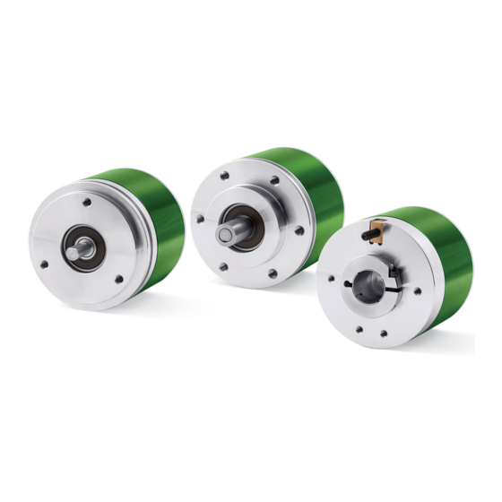
0 signal is output, but also choose for instance the voltage level of A, B and 0 output channels. IP58 / IQ58 programmable encoders are available in both solid (IP58, IP58S, IQ58, IQ58S) and hollow (CKP58, CKQ58) shaft versions. -
Page 8: Safety Summary
• elsewhere in this manual violates safety standards of design, manufacture, and intended use of the equipment; Lika Electronic s.r.l. assumes no liability for the customer's failure to comply • with these requirements. 1.2 Electrical safety Turn OFF power supply before connecting the device;... -
Page 9: Mechanical Safety
IP58, IQ58 - minimize noise by connecting the shield and/or the connector housing and/or the frame to ground. Make sure that ground is not affected by noise. The connection point to ground can be situated both on the device side and on user’s side. The best solution to minimize the interference must be carried out by the user. -
Page 10: Identification
Information is listed in the delivery document too. Please always quote the order code and the serial number when reaching Lika Electronic s.r.l. for purchasing spare parts or needing assistance. For any information on the technical characteristics of the product refer to the technical catalogue. -
Page 11: Mechanical Installation
• mount the flexible coupling 1 on the motor shaft; • make sure the misalignment tolerances of the flexible coupling 1 are respected. 3.1.1 Customary installation [mm] [mm] [mm] [mm] IP58, IQ58 50 F7 IP58S, IQ58S 36 H7 MAN IP58_IQ58 E 1.2 Mechanical installation 11 of 40... -
Page 12: Installation Using Fixing Clamps (Optional Kit Code Lkm-386)
[mm] [mm] [mm] IP58, IQ58 50 F7 IP58S, IQ58S 36 H7 3.1.3 Installation using a mounting bell (optional kit code PF4256) NOTE In order to guarantee reliability over time of the encoder mechanical parts, we recommend a flexible coupling to be installed between the encoder and the motor shaft. -
Page 13: Encoder With Hollow Shaft
Avoid forcing the encoder shaft; • insert the anti-rotation pin 1 into the slot on the flange of the encoder; this secures it in place by grub screw 2, preset at Lika; • fix the collar 3 to the encoder shaft. -
Page 14: Ckp59, Ckq59 Installation Using The Fixing Plate
IP58, IQ58 3.2.2 CKP59, CKQ59 installation using the fixing plate • Remove the antirotation pin 1 (see the Figure in the previous page); • mount the encoder on the motor shaft using the reducing sleeve 8 (if supplied). Avoid forcing the encoder shaft; •... -
Page 15: Ckp60, Ckq60 Installation Using The Antirotation Pin And The Fixing Plate
IP58, IQ58 3.2.3 CKP60, CKQ60 installation using the antirotation pin and the fixing plate • Remove the antirotation pin 1 (see the Figure on page 13); • fix the tempered pin 6 to the rear of the motor; • mount the encoder on the motor shaft using the reducing sleeve 8 (if supplied). -
Page 16: Electrical Connection
Shield Case Case * Available only on IP-, CKP- models 4.2 T12 cable specifications Model : LIKA T12 cable Cross section : 4 x 0,25 mm + 4 x 2 x 0,14 mm twisted pairs (24/26 AWG) Jacket : TPU, extra flexible Shield : tinned copper braid, coverage >... -
Page 17: M23 12-Pin Connector Specifications
IP58, IQ58 4.3 M23 12-pin connector specifications M23 12-pin connector Male Clockwise 4.4 M12 12-pin connector specifications Male Frontal side A coding 4.5 Connection of the shield For signals transmission always use shielded cables. The cable shielding must be connected properly to the metal ring nut 3 of the connector in order to ensure a good earthing through the frame of the device. -
Page 18: Ground Connection
IP58, IQ58 4.6 Ground connection Minimize noise by connecting the shield and/or the connector housing and/or the frame to ground. Make sure that ground is not affected by noise. The connection point to ground can be situated both on the device side and on user’s side. -
Page 19: Counting Direction Input (Ip-, Ckp- Models Only)
IP58, IQ58 setting input to 0VDC if not used. To set the zero position, connect the Index pulse setting input to +VDC for 100 µs at least, then disconnect +VDC. Normally voltage must be at 0VDC. We suggest moving the axis to the desired position, then activate the Index pulse setting function while the encoder and the mechanical assembly are in stop. - Page 20 IP58, IQ58 input to +VDC to have an increasing count when the encoder is turning counter-clockwise. Clockwise and counter-clockwise directions are viewed from the shaft side (see the Figure on page 30). WARNING The counting direction can be set also through the programming tool. The Counting direction parameter implies that the Counting direction input is set to 0VDC.
-
Page 21: Diagnostic Leds (Figure 1) (Ip-, Ckp- Models Only)
IP58, IQ58 4.10 Diagnostic LEDs (Figure 1) (IP-, CKP- models only) NOTE The Diagnostic LEDs are available only on IP-, CKP- models. Two LEDs located in the rear side of the encoder enclosure are intended to show visually the work status of the device as explained in the following table. GREEN Description (status) - Page 22 IP58, IQ58 way a unique position can be identified at a well-known point in the 360° revolution of the encoder shaft. The external button located in the rear side of the encoder enclosure allows to set the point in the revolution at which the 0 pulse will be output.
-
Page 23: I2C (Inter Integrated Circuit) Serial Connection
USB socket using the specific connection kit supplied by Lika Electronic upon request. The connection kit code is KIT IP/IQ58. It is provided with a terminal for connecting the cable of the devices having ZCU output circuit code. -
Page 24: Installing The Kit Ip/Iq58 Usb Drivers
You are required to install the drivers of the USB Serial Converter and the USB Serial Port first. The drivers are available for download at the address http://www.lika.it/eng/prodotti.php?id_cat=267&id_fam=271&filtro=170 . 4.12.1 Installing the KIT IP/IQ58 USB drivers Please follow the steps in the documents listed below to install the drivers of both the USB Serial Converter and the USB Serial Port of the KIT IP/IQ58. -
Page 25: Programming Interface
5.1 Configuring the encoder using the software tool IP58/IQ58 programmable incremental encoder is supplied with a software expressly developed and released by Lika Electronic in order to easily programme and configure the device. It allows the operator to set the working parameters of the device and monitor whether the device is running properly. -
Page 26: Starting The Program
(Inter Integrated Circuit) serial interface. To communicate with the encoder, you must connect the device to the personal computer through a USB port using the specific connection kit order code KIT IP/IQ58 supplied by Lika Electronic. For any further information please refer to the section “4.12 I2C (Inter Integrated Circuit) serial connection”... -
Page 27: Connection With The Encoder
You are required to select the series of the encoder you need to connect to instead. To do this open the ENCODER drop-down box and select from the options in the list: “IP58, IP58S, CKP58” or “IQ58, IQ58S, CKQ58”. The encoder model can be found in the label applied to the device enclosure. -
Page 28: Setting The Parameters
IP58, IQ58 the connected device. Furthermore the buttons and the commands become active. 5.4 Setting the parameters WARNING To save the data on the EEPROM permanently, after having entered the new value you must press the ENTER button in the keyboard. The parameter is saved instantly. - Page 29 IP58, IQ58 Example 1 Let's assume that the encoder is mounted on the driven draw roller of a slitter and the circumference of the roller is 753 mm. We can set a resolution of 7530 PPR (Resolution = 7530) to control the movement of the roller with a tenth of a millimetre resolution.
-
Page 30: Counting Direction
IP58, IQ58 As we know the reduction ratio of the reduction gearbox, we can set a suitable resolution in order to control the motion of the motor precisely and calculate the input speed starting from the known output speed. Example 3 Let's assume that the encoder is mounted on the SFI draw wire unit and the application has a 5500-mm long linear travel. - Page 31 IP58, IQ58 counter-clockwise direction (otherwise a count down when the encoder is Counting direction = CW to have the rotating in a clockwise direction). Set Counting direction increasing count when the shaft is turning clockwise; set CCW to have the increasing count when the shaft is turning counter-clockwise. Clockwise and counter-clockwise directions are viewed from the shaft side (see the Figure in the previous page).
-
Page 32: Index Length
IP58, IQ58 Index length This parameter allows to set the width of the Index pulse (0 pulse) expressed in electrical degrees. Two options are available and selectable in the drop-down box: 90° el (gated A, B) and 180° el (gated A). Please note that the 0 pulse having a width of 90 electrical degrees is synchronised with A and B pulses, while the 0 pulse having a width of 180 electrical degrees is synchronised with A pulse. -
Page 33: Output Circuit
IP58, IQ58 WARNING Please check the position of the 0 pulse and set it if necessary whenever you set Resolution a new resolution next to the parameter or reverse the counting direction. NOTE Index length The width of the 0 pulse can be set next to the parameter. -
Page 34: Max Rpm
IP58, IQ58 Max rpm It allows to optimize the encoder performance (by keeping the most efficient ratio between either the rotational speed and the precision in the case of the IP58 encoder; or the rotational speed and the edge distance in the case of the IQ58 encoder), depending on the maximum speed the application is able to reach. -
Page 35: Encoder Status
IP58, IQ58 Maximum counting frequency (kHz) * 60 * 1000 RPM = The reversed formula can be very useful -for instance- when you know the maximum counting frequency that is applicable to the system (because of the encoder, the following electronics and the cable length) and you need to calculate the maximum rotational speed the encoder is allowed to reach at the desired resolution. - Page 36 If an error occurs the system is not able to solve by pressing the CLEAR ERROR button, please take note of the error code that appears in the window and reach Lika Electronic's After Sales and Technical Service. Press the BACK TO MAIN PAGE button to display back the main page.
- Page 37 IP58, IQ58 Default parameters list Parameters list Default value Resolution 1024 * Counting direction Index length 90° el (gated A, B) Index position 5-30V (PP/LD Output circuit universal) Max rpm 9000 * 1024 PPR is the default resolution of the PROG order code version only, for instance: IP58-H-PROGZCU48RL2.
- Page 38 This page intentionally left blank...
- Page 39 This page intentionally left blank...
- Page 40 Please check the supply voltage specification in the product datasheet. Dispose separately LIKA Electronic Via S. Lorenzo, 25 36010 Carré (VI) • Italy Tel. +39 0445 806600 Fax +39 0445 806699 Italy: eMail info@lika.it - www.lika.it World: eMail info@lika.biz - www.lika.biz...
Need help?
Do you have a question about the IP58S and is the answer not in the manual?
Questions and answers