Table of Contents
Advertisement
Quick Links
Smart encoders & actuators
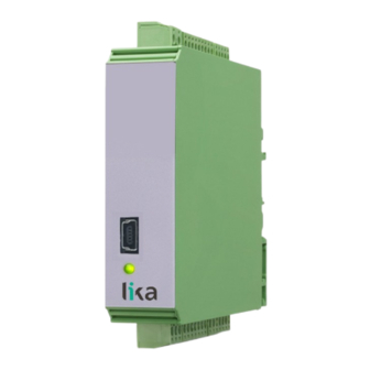
IF40
IF41
• IF40 signal converter (incremental to analog or serial)
• For HTL/TTL/RS-422/NPN/PNP incremental encoders and sensors
• IF41 signal converter (SSI to analog or serial)
• For single/multiturn SSI encoders up to 32 bits
• 16 bit analogue output -10 ... +10V, 0 ... 20mA, 4 ... 20mA
• RS-232 / RS-485 serial output
• Parametrization via free software and USB serial interface
Suitable for the following models:
IF40
•
IF41
•
Lika Electronic
User's guide
•
Tel. +39 0445 806600
General Contents
Preliminary information
1 - Safety summary
2 - Identification
3 - Mounting instructions
4 - Electrical connections
5 – Menus and parameters
6 - Appendix
7 - Modbus RTU Interface
8 - Parameters / serial codes
•
info@lika.biz
11
14
16
17
20
34
97
98
102
•
www.lika.biz
Advertisement
Table of Contents

Related Manuals for Lika IF41


Summarization of Contents
Preliminary Information
Device Operational Modes
Sets the desired measuring function for the device.
IF40/IF41 Functional Diagram
Visual representation of the device's signal processing flow.
Product Compatibility Overview
Compares the product with previous models IF50 and IF51.
Safety Summary and Precautions
General Safety Guidelines
Adherence to professional safety and accident prevention regulations.
Electrical Safety Precautions
Precautions for safe electrical connection and installation.
Mechanical Safety Guidelines
Guidelines for safe physical handling and installation of the device.
Device Identification Methods
Identifying Your Device
How to identify the device using its order code and serial number.
Mounting and Installation Guide
Device Physical Dimensions
Physical size and mounting details of the IF40/IF41 converter.
Installation Procedures and Environment
Procedures for device installation, including environmental and wiring aspects.
Electromagnetic Compatibility (EMC) Measures
Measures to protect against electromagnetic interference.
Device Cleaning and Maintenance
Procedures for cleaning and maintenance of the device.
Electrical Connection Details
DC Power Supply Connection
Technical specifications and connection for DC power input.
Auxiliary Voltage Output Details
Details on auxiliary voltage outputs for sensors and encoders.
Incremental Encoder Input Connections
Connection details for various incremental encoder signal types.
Mechanical Switching Contact Notes
Guidance for using mechanical contacts with inputs.
Absolute Encoder Input Connections
Connection details for absolute SSI encoders.
SSI Master Mode Wiring
Wiring scheme for SSI encoder when the device is Master.
SSI Slave Mode Wiring
Wiring scheme for SSI encoder when the device is Slave.
Start/Stop Encoder Input Connections
Connection of inputs for start/stop encoder signals.
RS-422 Signal Wiring
Wiring diagram for RS-422 signals in Start/Stop mode.
DPI Measurement Operation
How DPI measurement works with Init pulses.
Serial Interface (RS-232/RS-485) Setup
Configuration and connection for RS-232/RS-485 serial communication.
Analogue Output Configuration
Technical specifications and configurations for analogue outputs.
Control Input Specifications
Specifications and wiring for digital control inputs.
Control Output Specifications
Specifications and wiring for digital control outputs.
USB Serial Interface Connection
Connection and use of the USB serial interface.
Diagnostic LED Status and Errors
Explanation of the green LED status indicators and error codes.
Device Menus and Parameter Configuration
Menu and Parameter Structure Overview
Guide to the document's menu and parameter organization.
General Menu Settings
Main parameter settings including mode, encoder properties, and direction.
Frequency Mode Configuration
Settings for operating as a frequency converter.
Counter Mode Configuration
Settings for operating as a position transducer/counter.
SSI Mode Configuration
Settings for operating as an absolute value converter for SSI signals.
Start/Stop Mode Configuration
Settings for operating as a Start/Stop interface converter.
Preselection Values Setup
Setting preselection values or switching points.
Preselection 1 Settings
Configuration of switching conditions and parameters for Preselection 1.
Preselection 2 Settings
Configuration of switching conditions and parameters for Preselection 2.
Preselection 3 Settings
Configuration of switching conditions and parameters for Preselection 3.
Preselection 4 Settings
Configuration of switching conditions and parameters for Preselection 4.
Preselection 5 Settings
Configuration of switching conditions and parameters for Preselection 5.
Preselection 6 Settings
Configuration of switching conditions and parameters for Preselection 6.
Serial Menu Configuration
Configuration of serial interface settings like baud rate and format.
Analog Output Menu Settings
Configuration of analogue output settings like format, start, and end values.
Command Menu Input Actions
Configuration of input actions and functions for control signals.
Linearization Menu Setup
Setup for linearisation function to convert input signals.
Technical Appendix and Data
Serial Data Readout Methods
How to read data from the device using serial communication protocols.
Modbus RTU Interface Configuration
Modbus Parameter Setup
Required serial parameters for Modbus communication.
Modbus Communication Features
Explanation of available Modbus functions like Read/Write Registers.
Parameter and Serial Code Reference
General Menu Parameter Reference
List of parameters, serial codes, min/max/default values for the General menu.
Frequency Mode Parameter Reference
List of parameters, serial codes, min/max/default values for Frequency mode.
Counter Mode Parameter Reference
List of parameters, serial codes, min/max/default values for Counter mode.
SSI Mode Parameter Reference
List of parameters, serial codes, min/max/default values for SSI mode.
Start/Stop Mode Parameter Reference
List of parameters, serial codes, min/max/default values for Start/Stop mode.
Preselection Values Parameter Reference
List of parameters, serial codes, min/max/default values for Preselection values.
Preselection 1 Parameter Reference
List of parameters, serial codes, min/max/default values for Preselection 1.
Preselection 2 Parameter Reference
List of parameters, serial codes, min/max/default values for Preselection 2.
Preselection 3 Parameter Reference
List of parameters, serial codes, min/max/default values for Preselection 3.
Preselection 4 Parameter Reference
List of parameters, serial codes, min/max/default values for Preselection 4.
Preselection 5 Parameter Reference
List of parameters, serial codes, min/max/default values for Preselection 5.
Preselection 6 Parameter Reference
List of parameters, serial codes, min/max/default values for Preselection 6.
Serial Menu Parameter Reference
List of parameters, serial codes, min/max/default values for Serial menu.
Analog Menu Parameter Reference
List of parameters, serial codes, min/max/default values for Analog menu.
Command Menu Parameter Reference
List of parameters, serial codes, min/max/default values for Command menu.
Linearization Menu Parameter Reference
List of parameters, serial codes, min/max/default values for Linearization menu.
Serial Command Code Mapping
Mapping of serial codes to specific commands for the device.
Need help?
Do you have a question about the IF41 and is the answer not in the manual?
Questions and answers